![]()
![]()
![]()
1.1. LOCATION OF THE ZONE
The most favourable areas for a large development in the coming years of marine shrimp culture in SURINAME are located in the North-East of Paramaribo. Here, the Commewijne and Cottica rivers flowing from East to West (rare particularity on the guyanese shield) delimit a low coastal fringe that respectively sizes about 15 km and 80 km in the North-South and East-West directions.
Except in mangrove zones, swampy coastal areas and very sandy coastal zones, most of the lands were formerly improved with polders (about 2 centuries ago). Later, these polders were cultivated (sugar cane, cotton, etc…) but most of them are now abandoned and partly covered with forest trees. However, the basic infrastructures of these former polders such as dikes and drainage channels are still existing. The soil at the level of these reliefs is well stabilized ; thus, they would be useful for the implementation of the dikes of the future shrimp grow-out ponds.
2 sites where suggested by Mr P.G. PADLAN (FAO - Fisheries Dept) during his mission in SURINAME (December 1985) for the implementation of a shrimp culture demonstration farm. One is in the North West of Paramaribo (Weg Naar Zee) and one in the North-East of Paramaribo (on the right bank of the Commewijne river). As a matter of fact, between Mr PADLAN's mission and the present one, the Suriname authorities have selected the second site (see situation plan) where topographic and soil surveys were under course in November 1986.
During that mission, the experts could check the most important parameters of this site located on North-East of Paramaribo. This was made possible with :
- Visits on the site,
- An aerial survey of the coastal areas ;
- A strong and efficient support from the authorities and particularly the State Commission for Fisheries and the Soil Survey Dept.
1.2. SITE LOCATION
The selected site is located on the former “DE RESOLUTIE” polder, sizing about 600 ha. The polder is bounded on its northern part by the “JONKERMANS KREEK” which drains the north-western part of the Suriname river estuary. Field visits showed it was formerly utilized for the cultivation of sugar cane ; thus, it demonstrates the possibility to drain and dry the land with 100 % efficiency.
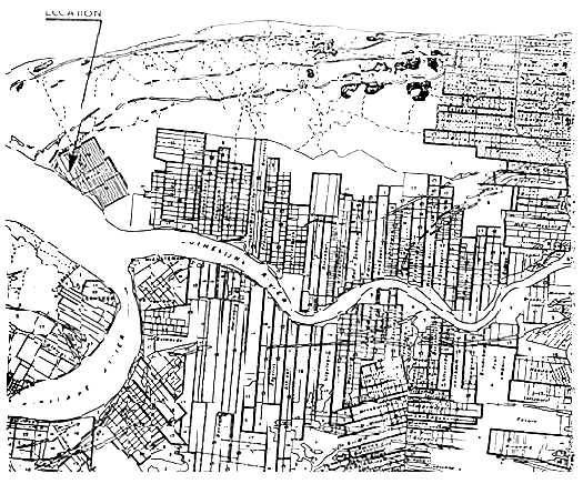
On that area, the separation dikes of the former fields are still present but eroded and covered with vegetation. The drainage channels are still partly efficient during the rainy season. However, due to the important silting in the channels, some fields are now permanently under water (about 15–20 cm of water depth). Anyway, that situation has partly delayed the return of the mangrove vegetation on the project site (see site plan).
1.3. SOIL CHARACTERISTICS
1.3.1. Pedology
The Suriname coastal areas show an almost constant pedologic structure from the Eastern part to the western one. It is a mostly flat land with clay soil that can be sometimes below the level of the highest tides. The penetration of marine water into these areas is directly in relation to the topographic levels. Thus, 3 types of vegetation can be observed in the swampy zones. They are :
- AVICENIA NITIDA (Zones covered with marine water) ;
- TYPHA ANGUSTIFOLIA (Zones covered with brackiswater) ;
- MONTRICHARDIA ARBORESCENS (Zones covered with freshwater).
Under the upper organic peat layer the soil is mainly composed with clay (60 % – 65 %) while the organic matter a content is below 2 %. The various components of that clay are the following :
- KAOLINITE 40 % - VERMICULITE 20 % - ILLITE 20 % - QUARTZ 20 %
H2S may be punctually observed in zones where Pyrit (FeS) was accumulated (more frequently in the western part of the Suriname river than on the eastern one). The soil pH usually ranges between 4 and 7.
Narrow sandy cords are punctually observed on the coast on the eastern part of the Suriname estuary (from the estuary to the Maroni river).
The selected site is quite representative of that general situation. However, the implementation of the demonstration farm will require to take the following precautions :
- The construction drawings of the farm (final design) should be based on exact and detailed topographic survey and soil samplings ;
- After removal of the organic top layer, digging works (earthworks) will be minimized in depth to avoid the oxidizing of the pyrit if any.
- For the same objective ; the surface of permanently emerged areas such as dike crests, etc… will be limited ;
- The sandy crest which is located on the boundary of the site will be kept. It will be utilized as a platform for the future project buildings.
Nota : Pyrit is rapidly oxidizing after contact with air and gives then H2SO4 after run-offs. The formation of H2SO4 will contribute to decrease the pH value inside of the grow-out ponds.
1.3.2. Topography
The vegetation and former infrastructures such as dikes make difficult an exact assessment of the site topography. However, the first collected data on 2 perpendicular axis allow to select the eastern extremity of the polder for the implementation of the future farm.
That zone shows the 2 following advantages : It is the closest to the Suriname river and is also connected to the JONKERMANS KREEK by a drainage channel.
The general slope of the land is gentle and almost constant from East to West (existing drainage channels) as it can be seen on the topographic plan. On the Kreek side the old dike gives a protection against the highest tides. Furthermore, the existing channel is downstream of the site (close to the estuary mouth). Under these conditions, the implementation of a pumping station on that channel will allow to pump marine water at high tide.
In relation to the existing data (topographic survey under course during the mission in November 1986), the quasi-totality of the site appears drainable after a minimum improvement. If the completion of the topographic survey does not confirm that statement (low probability) the project could be slightly shifted towards the East or South of the polder which show the same characteristics. This shifting could be done without questioning the basic technical components of the design.
1.4. WATER AVAILABLE AND MAIN CHARACTERISTICS
1.4.1. Silt
All along the coast of Suriname, the sea water has a high silt content due to the influence of the freshwater supplies. In relation to the seasons, the silt content may range between 400 and 4 000 mg/l and 12 hours settling are usually necessary to remove most of that silt. This characteristic of the water will impose to build a settling device upstream of the rearing ponds. That device could be either the main water supply channel (between the pumping station and the ponds) or one specific pond. As many existing ponds are available on the site ; the second solution will be preferred for the design of the demonstration farm.
1.4.2. Salinity
The selected site shows 2 possibilities for the intake of brackishwater :
- The JONKERMANS KREEK and
- The SURINAME-COMMEWIJNE estuary (in front of New Amsterdam).
During the mission, salinities were measured on the estuary side and compared with these previously recorded in New Amsterdam (daily measurements at 8 a.m. and 2 p.m. on both the Commewijne and Suriname sides since January 1st, 1986).
The comparision allows the following comments :
- In the estuary, the salinity usually ranges between 31 ‰ (high tide) and 7 ‰ (low tide). The values are higher close to the site due to the small waterflow of the Commewijne river ;
- During the main rainy season (May to August) and when the range of the tide is small, the salinity may constantly remain below 7 ‰ during few days (3–7 days).
- However, due to :
-- The buffer capacity of the settling pond ;
-- The pumping period (2 × 5 hours per day at high tide) ;
-- The small water renewal rate, 10 % per day only ;
The salinity should remain in the ponds at an optimal level for the grow-out phase (between 10 and 25 ‰) almost thoughout the year.
1.5. INFRASTRUCTURES
In Suriname, the cities and villages are not located on the coast but on the banks of the rivers and estuaries where the first colonial implementation started. The roads network is in relation to that history, thus, there is no direct access to the coast by road of tracks. On the other hand the natural hydraulic network has been completed with artificial channels (for connecting the different river basins) and results in means (boats, wharf, quay and bruyage) and knowledge that are fully adapted to a large fluvial traffic. The selected site can be easily reached by boat from Paramaribo within 45 minutes.
In the project, all the energy consumers such as pumps, vehicles, etc… will be driven by diesel engines. In addition, a small diesel power generator will provide electric energy for the domestic requirements ;
The freshwater table is very deep and the project size does not justify the implementation of a deep tubewell. During the rainy reason the rainfalls will be stocked and during the dry season the required quantities will be supplied by boat from Paramaribo.
Alike for freshwater during the dry season the required ice (necessary to transport the harvested shrimps) will be directly supplied from Paramaribo.
The village of fishermen, located on the outlet of the JONKERMANS KREEK will be a reliable source of labour force when workers will be required to harvest the shrimps in the project ponds.
1.6. JUSTIFICATION OF THE SITE SELECTION
1.6.1. Disadvantages of the site
It is located on the right (northern) bank of the estuary, thus, the logistic support is only possible by boat.
There is not a direct access (too costly for a small demonstration plant) to the sea water. However the salinity of the available waters is such that there will not be a negative impact on the growth of the animals. In the future, the commercial farms will have to pump the water directly at the level of the seashore.
1.6.2. Advantages of the site
It is close to the capital (it can be reached within 45 minutes by boat). That point will make the logistic support easier and more efficient.
As regards soils conditions and topography, the site is fully representative of the zone. In addition that zone is the most favourable for the development of shrimp culture in Suriname on short term.
As regards the necessary logistic support by boat, the demonstration farm will be very representative of the future industrial farms in the zone.
1.6.3. Conclusion
The selection of that site is not the result of a complete and rational methodology with successively :
- Inventory of potential sites,
- Evaluation of their characteristics (advantages and disadvantages),
- Final selection.
However, an objective analysis of its characteristics shows that it positively fulfills all the usual and major requirements of a demonstration farm. These constraints are :
- Possibility of an efficient logistic support,
- Bio-technical representativeness of the site as regards further development in the region ;
- Possibility to build and run the facilities at an acceptable cost.
2.1. GENERAL DESCRIPTION
The whole farm will cover about 50 ha with :
- One pumping station,
- One water storage settling ponds, water storage/settling pond,
- 4 grow-out ponds (5 ha each),
- One water storage drainage pond,
- The logistic area (office, laboratory, etc…).
The rest of the land will be occupied by the access, dikes and channels.
2.2. PONDS
2.2.1. Grow-out ponds
As demonstration ponds their size should allow a direct application of the observed results to the future industrial farms. To achieve that objective, each pond will size about 5 ha (310 m × 160 m).
As a bio-technical demonstration of the pregrowing phase is not required, such pregrowing ponds are not included in the design of the farm. The grow-out ponds will be directly restocked with imported P30/P40 (30–40 days old Post Larvae). That decision has the advantage to reduce the initial investment cost.
From the water inlets to the water outlets, the water depth will progressively increase from 0,80 m to 1,20 m. The dike crest will be 0,30 m above the water level in the ponds.
The design of all the dikes will allow a traffic of light vehicles and they will be efficiently protected against erosion. The crest width will be 5 m and the slope of the bank will not exceed 1/2 (one unit of height for 2 of width).
2.2.2. Water storage/settling pond
With a 10 % water renewal per day the total daily requirements of the farm are 20 000 m3. Due to the particular geographical position of the site (non availability during few days of marine water at low and high tides during the raining season) a water storage with 2–3 days of autonomy is required i.e. 60 000 m3.
In the upper part of the site, one former field of 10 ha will be utilized for that purpose. However, an improvement and lifting of the existing dikes will be necessary. For covering the storage requirements (60 000 m3) the water surface will be 0,60 m above the water level in the grow-out ponds.
With such a buffer volume, settling should be efficient. In addition ; it will be improved by the implementation of chicanes (low dikes) inside of the pond.
2.2.3. Water drainage pond
Gravity drainage of the grow-out ponds is impossible at the highest tides. To solve that problem, a buffer water storage pond is necessary between the outlet of the ponds and the river. 2 ha of land will be prepared for that purpose. The buffer capacity will be 10 000 m3.
2.3. HYDRAULIC CONCEPT
2.3.1. General organization
One pumping station will be built on the bank of the Jonkermans Kreek. It will supply water directly into the water storage/settling pond though and existing former channel. The water will be then transferred by gravity into the grow-out ponds though one main channel.
Each pond will be equipped with 2 inlet gates and 2 outlet gates (for drainage and overflowing). From the outlets the water flows in a drainage channel to reach the water drainage pond. That pond discharges only at low tides in a former channel draining the water to the river.
2.3.2. Pumping station
As previously described the daily water requirements are 20 000 m3. To get marine water with a maximal salinity, the station will work only at high tide i.e. : 2 × 5 hours/day. Under these conditions, the pumping capacity will be at least 2 000 m3/ hour (560 l/s).
The station will consist of 3 diesel driven pumps, each one with a 1000 m3/h capacity (one in stand by).
2.3.3. Water distribution network
The head of pumping will be calculated for all the water transfers to be possible by gravity (supply and drainage) from the pumping station to the grow-out ponds and then back to the river.
The height of water in the water storage settling pond will be variable. However, a regulation device at the outlet of that pond will control the water height in the water supply channel (constant level).
Each inlet gate of the grow-out ponds will be sized to allow a water flow ranging between 0 % and 50 % of the pond volume per day.
2.3.4. Water drainage network
Each grow-out pond is equipped with 2 outlet gates allowing to drain both the surface and bottom waters.
A drainage channel connects these outlet gates with the water drainage pond. From that pond, the water flows back to the river though a former drainage canal. The outlet of that water storage pond is equipped with a dump valve, thus, the river will not directly enter into the pond at high tides.
2.4. OPERATION BUILDINGS AND MISCELLANEOUS WORKS
One platform will be prepared close to the grow-out ponds for the construction of 2 operation buildings.
A - One office building with :
- One office (10 m3),
- One laboratory (10 m3),
- One small flat for the keeper (40 m3),
- WC,
- One room for the power generator.
B - One technical building with :
- One workshop and store (25 m2),
- One food storage hall (15 m2),
- One opened and covered parking (20 m2).
One adapted tank will be designed and built to receive the rainfalls. One shed will be built to protect the machinery of the pumping station and one light pontoon will facilitate the manipulations for the logistic boat.
2.5. EQUIPMENTS
2.5.1. Vehicles, boats and mobile equipments
One boat will be necessary for the logistic needs from Paramaribo (goods, materials, freshwater, staff transportation, etc…). It will be a wooden boat, locally made with a 50 H.P. outboard engine. For the fishing operations, it will supply ice from Paramaribo and will bring back the shrimps to the processing plant in Paramaribo (if necessary, because the shrimps could be locally sold as fresh product). For these 2 purposes (transport of ice and shrimps) it will be equipped (when required) with a mobile isothermic box.
2 light boats are necessary to feed the shrimps in the grow-out ponds. They will be aluminium made (locally made) with a 5 H.P. outboard engine.
One 30 H.P. tractor will be utilized for various needs and maintenance. It will be equipped with one loading platform (transportation of goods) and one rotary cultivator (preparation of the ponds bottom).
One mobile dredger will be necessary for dredging the channels and the water storage/settling pond from the banks.
2.5.2. Other equipments
- Laboratory equipments such as :
-- pH meter,
-- Oxygen meter,
-- Thermometer,
-- refractometer,
-- Binocular,
-- Dynamometer,
-- Scales, etc…
- Fishing equipments such as :
-- Nets, fish boxes, mobile power generator (1 Kw) with projector.
All the costs are considered on a basis November 1986.
The total investment cost amounts to S.F1. 1.100.000 with 62 % in foreign component and 38 % in local currency.
The construction period will last 2 dry seasons i.e. 2 years with 55 % of the total expenses on year 1 and 45 % on year 2.
Such a pilot/demonstration farm is more costly than bigger farms as it can be seen on the following table :
| PILOT FARM (20 HA) | 50 HA FARM (1) | 500 HA FARM (1) | |
|---|---|---|---|
| Cost in S.F1. per ha of pond | 54 800 | 35 400 | 28 800 |
This is mainly due to the following factors :
- The considered surface per pond is 5 ha only for the pilot when it is 10 ha for the commercial farms ;
- The required equipments, vehicles and infrastructures are not proportional with the surface ; thus, their cost per ha decreases when the total surface increases.
The breakdown of the total investment cost of the pilot farm and the calculation of foreign component are shown in the table of the following page.
TOTAL INVESTMENT COST OF THE PILOT FARM
WITH PLANNING AND FOREIGN COMPONENT
| ITEMS | LIFE PERIOD EXPECTANCY | TOTAL COST (S.F1.) | Y E A R S | % OF FOREIGN COMPONENT | |
|---|---|---|---|---|---|
| 1 | 2 | ||||
| Earthworks | 15 years | 185 800 | 117 000 | 68 800 | 25 % |
| Hydraulic structures | 15 years | 167 200 | 50 000 | 117 200 | 65 % |
| Engineering | 15 years | 77 310 | 37 310 | 40 000 | 0 % (1) |
| Shed | 10 years | 12 400 | - | 12 400 | 45 % |
| Building | 10 years | 30 000 | - | 30 000 | 65 % |
| Miscellaneous | 10 years | 75 390 | 25 000 | 50 390 | 60 % |
| Pumps | 7 years | 120 000 | - | 120 000 | 90 % |
| Vehicles | 5 years | 325 000 | 300 000 | 25 000 | 90 % |
| Boats | 5 years | 80 000 | 70 000 | 10 000 | 45 % |
| Technical equipment | 3 years | 12 000 | - | 12 000 | 90 % |
| Fishing gear and office equipment | 3 years | 10 000 | - | 10 000 | 25 % |
| TOTAL | 1 095 100 | 599 310 | 495 790 | 62 % | |
| (55 %) | (45 %) | ||||
![]()
![]()
![]()