![]()
![]()
![]()
Since all ponds have impermeable bottoms, whether natural or artificial, beds for housing SWS Units must be introduced. The following procedure is suggested:
1. Medium
Most sand seems to be dug from river beds where it is constantly being deposited. Much contains a high proportion of particles below 1 mm but the quality varies and average particle size is larger when the flow is fast. Sand should preferably have not more than 10% below 1 mm with most between 1 mm and 4 mm. If the sand is fine and dirty, it can be quickly washed in a concrete mixer with water hose running, the best procedure being found by trial.
2. Siting
A corner of the pond is best. Its existing banks form two sides, the others being made by walls of roughly piled rocks or blocks. See Fig 1 & 2. If the area is close to the overflow to next pond, it has most water movement over the surface. Nearly all pond water is already dirty and it is essential to draw from a pond where the mud is not being stirred up by fish such as large carp, for this can add unnecessarily to the filter load. It is best to use a small pond without any fish or divide off a section of a large pond containing only small or surface fish.
3. Size
An area of not under 3 m × 3 m is suggested, with a final total bed depth of c. 65 cm in centre, i.e. including Unit, and tapering to c. 30 cm at edges. See Fig 1 and 2.
Good sand is available at very low cost in most parts of the country and the biggest beds practicable should be made. These will allow maximum volume and also last longer between maintenance. Even a bed 5 × 5 m and 75 cm deep would cost under 20,000 Rupiahs. At 24 m3/h, this is equivalent to a surface flow rate of 16 1/m2/min, which is within the flow for maximum quality slow sand filtration.
4. Construction
Although the work can be done while the pond is full, it is easier and quicker when pond has been drained for cleaning. The operation is as follows, all figures being taken as approximate:
Clear away mud to leave hard bottom.
Complete sides by building rough walls of rocks, old bricks etc. 30 cm high.
To allow good access of water and keep the Unit above clay bottom, two different methods are possible and the more convenient should be used:
Put down a circle (1 m dia.) of stones 5 cm diameter and depth of 10 cm.
Put a large rock or block 10 cm. high under each corner of Unit. See Figures 1 and 2.
Pour sand to depth of 15 cm and put Unit in position. Press down firmly but do not stand on it. If pond is empty, let the water start filling it.
Add gravel/sand to water (to stop forming air pockets) until centre has total depth of 65 cm sloping to 30 cm at edges. If a large stone of 15–20 cm thickness is placed on top of Unit, it indicates depth of sand and holds it steady.
5. Development
Thorough development is essential - it may take a whole day, with many stop/starts to reach maximum volume and top quality. If the sand contains much fine material and progress is slow, it will help to blow back briefly at low speed several times while somebody stands on the Unit to hold it in position. “Briefly” means not more than 2 or 3 minutes after the water has reached the Unit. Several times in this way will be more effective than a longer single period. See pp 2 and 7 of Appendix 11.
As explained elsewhere, in the high ruling temperatures of this area, continuous running is essential to maintain the aerobic conditions required by a biological filter. Once development by petrol-driven pump is complete, this should be replaced by a 2 or 3 h.p. electric pump.
6. Water Quality
The raw water in the Sukabumi and Grobogan fish ponds was more polluted with organic matter than in any previous tests. In both, there seemed to be complete removal of all algae and organic particles, leaving only faint milkiness caused by fine clay particles already discussed. These particles are probably too fine to be taken out by any filter. At the end of development, particles will be removed to c. 2 microns including Lernaea.
After c. 7 days of pumping, the bed will become a biological filter and the following extra results are expected:
Reduction of ammonia by c. 80% and of BOD and detergent by c. 50%.
Removal of above 75% of all bacteria but this could be as high as 98%.
Marked reduction in D.O. level, since the oxygen has been used to oxidise polluting materials. This is simply restored by cascading etc.
Note: It is difficult to give definite figures for quality, because
Conditions in these ponds vary widely, especially as regards algae, both free and surface.
The temperature is higher than in any other outdoor work we have done. The biological activity is, therefore, high and results may be better than suggested.
7. Maintenance
See p 7 of Appendix 11. Since most material removed is probably organic, this should break down leaving few solids, but only experience will show how quickly the volume is reduced by blocking. Simple raking of the surface followed by redevelopment while pumping to waste should not take above 2 hours, and may take much less. It may prove useful to do this on a routine basis.
Conditions are very different from ponds in temperate zones. It is suggested that a system is established at one or two centres and fully observed for at least a month before it is used generally, but it should give much improved water for hatcheries and fry-rearing.
Need to be Patient!
Full preparation of site and very complete development are essential, even if each may take a day or more. A source is being established for use during months or even years and there is no point in trying to do this in the shortest time. Once the system has been formed and development begun, it may be enough to leave a workman in charge, stopping and starting frequently, and gradually bringing the volume up to full flow.
Although it is possible only in hilly country, gravity abstraction from SWS Unit is worth considering for providing clean water to breeding ponds at no cost for power, once the system is fully established. It can run by siphon but it is better to bring a pipe through the pond wall and thus have a permanent head of water. In theory, a total head of 1 m, i.e. from water surface to outflow, can give a volume of c. 30 m3/h from a 50 mm pipe. In such condition, considerably less could be expected but the pipe should be fitted with a control valve and also a U-joint to keep the line full of water.
The screen well, which is ideal for working at depth, is not recommended for artificial beds or shallow formations, for the following reasons:
It appears easy to insert but it is equally easy to disturb. In contrast, pumping holds the SWS Unit down.
Any erosion or removal of sand can quickly expose the screen to raw water.
Most important, when the Unit is installed and covered, all water must travel down through the sand to the depth of the Unit and then up. In fact, most of it travels much farther, from several metres. There is no such minimum imposed by the well screen.
The bed can be much more fully developed by the Unit.
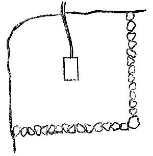
Fig 1. Plan (Not to scale)
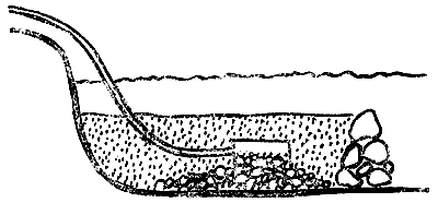
Fig 2. Section (Not to scale)
Final Note:
The construction of artificial beds for obtaining improved water from fish ponds is described above, with the possibility of running by gravity, thus cutting out cost of power after original establishment. This method is being used in several countries for supplying water to isolated communities in hilly areas.
The Unit is placed in a sand-filled collection area, either natural or artificial and a pipe is then taken through the containing bank or wall to ensure a permanent head of water. In some cases, only a ½" pipe feeding into simple storage and running to waste is needed. This can provide 24 m3 daily from a sand bed of 2 m2, and unless the source is grossly polluted, the water will be close to western potable standards. We believe that this possibility is worth notifying to authorities concerned with water in areas beyond the reach of piped supplies.
This has the following advantages over normal bottom drainage:
Washing back is simple. Surface dirt can be removed by either suction, syphoning or overflow according to lay-out.
Brief development after washing back allows removal of fine particles and re-formation of graduated, free-flowing bed.
Advantages over pressure filters are:
It forms a suction system. Pressure can never reach one atmosphere, so that larger organisms cannot be distorted and pushed through the sand.
While the surface Schmutzdecke is basically a physical filter, the whole bed down to at least 15 cm becomes biologically active, consuming bacteria and processing all biodegradable matter. This is not true of a pressure system.
In both labour and hardware, such a system is cheaper to install and run than either other type, especially pressure filters.
The following general pattern is suggested. All dimensions should be read as “approximate”; very accurate measurement is not needed and it is enough to be within about 1 0%.
Unit base must be raised 15 cm above floor to allow free water access. This can be done in 3 ways -
If coarse coral is available, this can be used to cover whole of bottom. This is also useful in maintaining pH.
A layer of stones up to 7 or 8 cm diameter, either across whole bed or, if scarce, over circle 1 m diameter under Unit.
If above not possible, place larger stone or block under each corner.
2. Filter Medium
Work on such systems in U.K. and elsewhere shows that the best material for main bed is small mixed gravel or crushed granite of 2–5 mm. Depth of the layer is 40 cm where bottom is entirely covered: 55 cm when Unit stands on stones or blocks. Of this, 10 cm should be put down before Unit is placed in position. Finally, a layer of sand 7 cm deep and of 1–2 mm grains should cover whole surface. Coral breakdown material can be used for whole of main bed, if fractions below 1 mm and above 10 mm are excluded, but thorough cleaning is essential. Some river sands are suitable without grading.
Note:
It will usually be more convenient to construct the system dry, but it must be filled slowly from below, by forcing a pipe down one corner, to drive out air.
The actual filter surface is formed not by sand grains, however small, but by the much finer particles strained from the water to form the Schmutzdecke (dirt layer). So it is not necessary to use very fine sand for the top dressing.
3. Development
In such a system, this should be quick because the bed is already clean and graded, but it must be thorough and procedure in Appendix 11 followed until flow of well above required volume is reached. A mobile pump, petroldriven, with variable speed is needed. When development is complete, connect to electric pump of correct power and pump continuously for one week, either to waste or by recirculating, with monitoring of important parameters. The entering or returning water should do so in a way not to disturb the bed surface. This applies to both development and normal running.
4. Area/Flow Ratio
In favourable water conditions, a flow rate of up to 1.3 m3/m2/hour is possible but if space is available, it is better to use 0.5 m3/m2/h. In all cases, efficiency will be improved by allowing larger particles to settle before reaching filter. A minimum water depth of 30 cm is suggested.
5. Maintenance
When reduced flow of, say, 20% shows that the surface is becoming blocked, and not before, action should be taken on principles in Appendix 11, i.e. raking surface and pumping back. Because the area is enclosed, the dirty water must then be pumped or siphoned off, or allowed to overflow. Finally, the bed is redeveloped briefly. Make sure the Unit stays in position: a rock of not under 50 kg, put on it during formation, will hold it down for the pumping back. If the filter is under cover, it might be possible to hold it firm by a vertical beam.
6. Aeration
All biological filters reduce D.O. level because oxygen is used up. The filtrate should, therefore, be aerated before use by cascading, injection, etc. The following diagram shows a simple method of doing this.
Note: Filter efficiency depends on the bed organisms being alive and supplied with oxygen. Continuous pumping is essential and if the raw water is very low in D.O. this should be increased in ways suggested above.
The above applies both to filter beds at ground level that must be
pumped and those that have been run by gravity. The latter will already have
some opening(s) at or near base level and the Unit take-off must be brought
through this or through a specially made opening below minimum water level.
This is to ensure a permanent head of water. The formula for calculation flow
is V =  when V = velocity in m/sec; g = 9.31; and H = height in metres.
The head H is in two parts: (a) positive, i.e. the water over the Unit, and (b) negative, i.e. the suction in the down pipe from Unit take-off. The latter should have a control valve both to restrict flow, if this is excessive, and also to ensure that the down pipe is kept full of water to maintain the negative head.
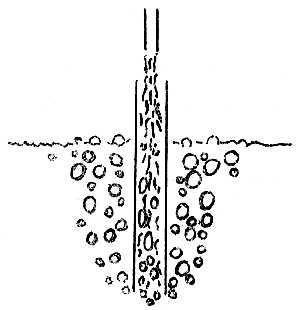
Fig 3. Simple Method of Aerating the Filtrate
Communication was not very easy and some details were not clear, but it seems that the reservoir c. 2 m × 2 m and 1.75 m deep can be filled between c. 17.00 and 22.00 during the rainy season and this lasts for 2 days, i.e. a consumption of under 4,000 1/day. In the dry season, it takes longer to fill. Part of this is used by 3 or 4 households and the remainder for fish-washing, etc. The village in general did not use it, but I failed to find out their source.
The system consists of a tube well at c. 6 m deep (?), duplicate electric pumps, run off the diesel generator which is used nightly, and an overhead reservoir. The pipe delivers directly into the reservoir, keeping solids in suspension, while the outlet is only c. 4 cm above the floor, therefore, certain to draw off silt especially in the period after filling. The whole is heavily constructed, obviously at a cost out of proportion to results. The pump was run for an hour and the water sampled directly from it at intervals. Quality was consistently poor, confirming that intermittent pumping was not the cause, since an initial flush of silt would be followed by progressively better water. One must assume that the tube well was driven into an aquifer which cannot give in situ filtration. Perhaps no other is accessible. It is unfortunate that provision was not made for a larger supply, by sinking a complex of tube wells (at little extra cost) and including a simple sedimentation or filtration system. From tests carried out, it seemed that the former would largely solve the problem.
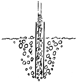
Any major alteration to the basic system would be costly. An orthodox filtration system can hardly be considered on both cost and practical grounds. The following cheap and simple method is, therefore, suggested. Research work in U.K. has developed an SWS mini-Unit of cross section 15 × 15 cm, with capacity of above 1 m3/h. This can be housed in a plastic container such as is used for chemicals. A useful size is diam. c. 40 cm and cut off to give depth of c. 30 cm. This is filled with sand/gravel and the Unit placed in it, the take-off coming through side and connected to down supply pipe (see Fig 4). This has the following advantages:
This is a gravity system and needs no pump.
It will exclude all silt and give good quality water.
Since the sand/gravel level is at c. 30 cm, most silt will settle around it and not be drawn in. A piece of stiff plastic slanting above the filter will divert sediment away from it.
The only likely disadvantage is that water cannot be drawn from below c. 30 cm, thus reducing capacity of reservoir by c. 15%, but the take-off could emerge from the side and reduce this height if this is important.
Well-washed coral sand is suitable for filling. To develop the filter, use the tap below reservoir, allowing water to run and then stop a number of times until clear.
Maintenance
The reservoir must be cleared of silt from time to time. If reduced flow suggests that the filter surface is becoming blocked, the container can be taken out when the reservoir is empty, the gravel washed and replaced, with short re-development.
The above procedure involves very little plumbing and does not call for technical skill. The mini-Unit is now starting production.
We understand that a further order for Village Units will be placed and we shall be glad to include 2 samples of mini-Units, one for Camplong and one for testing elsewhere. This could be a cheap and simple way of improving water supplies for small communities in hilly areas generally.
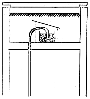
Fig 4. SWS Mini-Unit with Gravity Extraction
Disturbance of coastline by harbours, breakwaters etc. causes both erosion and deposition of silt and sand, and it is just possible that sand banks of adequate size may have formed inshore. If such can be found within, say, 100 m, by probing from a boat, it might be worth considering. Major considerations are cost and vulnerability of pipe line. For the small flow needed, this need be only 50 mm diameter. Such search is doubtfully justified.
At a convenient point up to c. 20 m from the shore line, a pit should be dug c. 2 m × 2 m and 1 m deep, so planned that it is fed by water until an hour or so before low water. (In fact, the terrain may be too difficult for a pit to be dug.) Line bottom with stones and construct bed as suggested in detail for fish ponds, using SWS Unit. When pit is complete, cut connecting tunnel to sea at correct height and fill with stones, branches etc. as a rough screen to exclude rubbish. This may be difficult to plan on such a shore and it might be simpler to dig a larger pit filled for say 2 hours each side of high water and acting as reservoir.
Required volume is average of under 1 m3/h, and even a small bed will give a slow filtration rate. Continuous pumping should take place for at least one week, preferably 4 weeks, with the water being monitored. A petrol-driven pump must be used for development, running at low speed, but then a small electric pump may be fitted for permanent use. Performances vary, but a motor of 0.5 kw should give a steady flow of c. 1.5 m3/h.
Optimum filtration efficiency demands continuous running, even if some water runs to waste. If quality is good, simple storage must be provided to give gravity feed. Of 20 m3/day, it is reckoned that 10 m3 is used during the morning. For a supply of c. 1.5 m3/h, a storage capacity of 5 m3 should be enough but the reservoir size is easily calculated when pumping rate and pattern of use are known.
Only actual pumping will show whether this is practical but the cost of a trial is small. The amount of filter cleaning cannot be forecast, because nothing is known of the pollution details. Much of it is probably organic and, therefore, biodegradable, and this causes less build up on the surface than mineral particles in suspension.
Help was asked about a water supply (from a nearby river) for the new fishing village of c. 2,500 people. There was not enough time to run tests, but the problem is somewhat similar to that of the nearby fishing harbour, as regards sand quality, and the following suggestions are made:
Avoid the part of river alongside market and consider the c. 200 m upstream of it, making sure of being above highest point reached by brackish water at high tide.
Using yellow probe look for suitable strata of sand along banks, going to at least 2 m.
If (2) is not good, which is probable, prepare an artificial bed in a little bay formed in the river bank, using procedure more or less as for fish ponds and a surface area of c. 3 × 3 m.
As the water must at present be carried from central point, the daily use per person is not more than 10 litres and perhaps much less, making total of only 25 m3/day. The existing storage holds c. 20 m3 and a pump need give a volume of only 1.5 m3/hour to keep it full. With electricity supplied for c. 17.00 to 23.00, a larger pump would be needed to fill the reservoir at c. 4 m3/h. When the pump is started, it should run to waste for 5–10 minutes. Continuous pumping at that lower rate is much more efficient.
If the people have been using raw water, there is no need to treat the filtered water, for it is much-improved. If they are used to town supply, slight chlorination may be needed after testing it.
Although the following note is mainly to meet the need for simpler and more effective filtration at the Brackish Water Centre, Jakarta, these two basic methods are effective for salt or freshwater tanks generally. Both are economical in space and material and are simply maintained. They are essentially biological filters and equally efficient, and are being used successfully in large tropical aquaria in U.K. with heavy stocking. The choice of type is by convenience, for one is likely to fit more easily into an existing circuit than the other. Designed for flows of up to c. 1 m3/h they can easily be scaled up by having 2 or more systems in parallel.
External Plastic Container
A dustbin (trash can) of 80–100 l. capacity is ideal, but if an old plastic drum of similar size can be found that is strong enough, this is equally good (Figure 5).
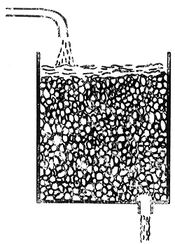
Fig 5. Drum Unit for Salt or Freshwater Tanks (Not to scale)
Make a hole close to bottom and fit suitable outlet. Unless the container is to rest on a concrete slab, prepare a strong support, for when full it may weigh above 200 kg. When in position, fill to within 15 cm of top with 2–5 mm gravel. Cover surface with sheet of glass or nylon wool in such a way that all effluent must flow through it. This sheet removes suspended matter and is changed or cleaned from time to time as it becomes visibly blocked. The mass of gravel becomes a biological filter within 7–10 days in a temperature of 26– 30°C and this should be left undisturbed as long as possible, certainly for at least 6 months. When this must be cleaned, some should be set aside, unwashed, to serve as culture to start biological filter quickly.
This method is most suitable when the existing main tank overflows to filter, storage, etc. Within reason, the larger the container the better, for it allows the water to flow over a larger active surface.
SWS Mini-Unit Housed In Gravel
This involves the use of a small electric pump - c. 200 watt - which may already be in use for circulation. An old container as discussed above, is cut in half and filled with gravel in which the mini-Unit is housed. The grade specified above should be used for the greater part, with a topping, 4 or 5 cm deep, of clean, well-washed sand. See diagram (Figure 6).
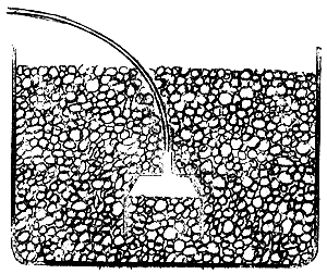
Fig 6. SWS Mini-Unit Housed in Gravel (Not to scale)
This is placed conveniently in the tank and serves as a self-contained sub-gravel filter. Massive development is not needed but it should be stabilised by pumping to waste over 3 or 4 stop/starts for, say, 10 minutes. This biological filter takes at least a week to become effective and it may help to add a little sand or debris from the tank bottom to seed it.
Standing clear of the tank bottom, it receives little silt: even in heavily loaded and fed tanks, the flow remains stable for 4 and 5 months without attention. The simplest way of cleaning, when reduced flow makes it necessary, is to remove the container, wash the sand/gravel and replace, also keeping a small amount of dirty gravel for seeding. This is suitable for systems housing small crustacean larvae, for it works by suction at a flow rate that does not draw down the larvae to the bottom surface. Accumulated fibrous debris on the tank bottom needs to be removed by syphoning from time to time.
Both of the above filters will process ammonia and other metabolites and reduce the need for water replacement, especially if the systems are only lightly stocked with larvae. It must be noted that this biological activity uses up some of the D.O. and this must be restored by cascading, injection, etc. One simple device for this is illustrated. Particularly with sea water, if there is any risk of a diminished pH, it is useful to use coral breakdown sand as a medium. This is easily obtained from many localities.
(Fig 3.) repeat Replacing oxygen by cascading the water.
This site is ideal for the use of stainless steel screen wells, which can be placed at a selected depth by jetting. The general procedure for this is given in Appendix 7. This referred specifically to the estuary at Tegal, Java, where conditions are similar. The following points refer particularly to Navotas but are also applicable more generally.
Equipment - that was used in the tests was not entirely suitable and the following is recommended:
Replace the galvanised iron pipe with heavy grade P.V.C. or Durapipe, with elbow at top end to connect firmly to the delivery/suction line. Any air leak at this junction reduces efficiency.
Replace heavy rubber by lighter flexible armoured P.V.C. such as Heliflex.
Borrow a pump of rather greater capacity to give more jetting power.
Because of the depth of water, anyone standing in it has not enough weight to apply when jetting. A boat 3 or 4 m off the steps will make the operation much easier. Solid foundations and large boulders prevent work within 2 m of the steps.
Water quality will not necessarily improve with depth and there is no point in having the top of the intake zone more than 1 m below the bottom of the silt zone. The permeable stratum seems to consist mainly of small broken shell and to extend for some distance. Thus, there may be little variation, but it is as well to test at several points and depths, as suggested in Appendix 2 para. 1, 2.
It was stated that 5–10,000 g/h would be used at certain periods and to supply this two well screens of 2" diameter and 24" screen length are suggested, connected to a 5 h.p. pump through a Y-piece and pumping only as needed. A much sounder alternative technically is to create storage and use a smaller electric pump to work continuously through 24 hours. This would require only one well screen.
The shell stratum seems very open and develops quickly. For a permanent source, it would probably be useful to wash back briefly a few times to ensure a broader zone and it is also suggested that the yellow test probe should be jetted down 6 or 8 times at 1–2 m distance around the selected point and then briefly developed, thus cleaning a large zone and making it into potential abstraction area.
The water will be free from suspended matter and physically clean, but it is impossible to suggest what degree of biological filtration will take place. This could well be high and it was suggested that tests be made after a week's running. At worst, the water will be suitable for washing down floors, boxes, ships, etc., but it should be suitable for washing fish also. Best quality results from continuous running, even if this means some running to waste. It is expensive to come back and put in larger pipes, so piping, etc. should be dimensioned for maximum flow needed in foreseeable future.
Main Fishing Harbour
The water off the wharf is said to be 3 or 4 m deep. Screwed 2 m extension pieces of heavy P.V.C. pipe are needed, of total length of 8 m, though three lengths may be enough. The pipes should end in male screws and be joined by double female screwed sleeves of 8–10 cm length. Probing and test-pumping is done with yellow test probe, as above, but it will probably be impossible, at this depth, to insert a screen well alongside it. The following procedure is simpler:
After a suitable position has been found, the yellow probe is withdrawn and the hole marked with a long stick. Then replace yellow probe with stainless steel screen well with jetting end: this can be fitted to any size and although it is more expensive than a plain screen, it is the only effective method on such a site.
It is suggested that the site is thoroughly tested first and, if favourable, the screen(s) can then be ordered to provide the volume required.
On certain sites, screen wells should be used to exploit under-water sources that cannot be effectively tapped by the SWS Unit, e.g. the Tegal river in which a more or less impermeable stratum of compacted silt and gravel overlies a permeable lower bed. This is probably typical of other estuaries subject to seasonal variation in flow and transporting sand from the higher reaches. The correct method of installation is as follows:
Using the SWS jet-probe (as demonstrated at Tegal) on the delivery line, explore the bed thoroughly to a depth of 2 m and, if necessary, to 3 m. With experience, the type and depth of bed can be accurately assessed; the changes in texture, i.e. sand, gravel, etc., are easily felt, while the water welling up the hole brings particles which can be collected in the hand and examined.
When an apparently suitable site has been found, interchange suction and delivery pipes and develop briefly. If necessary, test at different depths and sites to obtain maximum flow of high quality water.
In estuary situations, monitor the salinity while pumping until a stable reading is obtained; in a reach subject to tidal action, the salinity should be monitored through one tide. (This is necessary only if water of a particular quality is needed; for fish markets and some fish ponds, this is not important.)
When the suitability is confirmed, stop the pump and withdraw the probe, measuring carefully the depth of intake zone below the river bed. Mark hole with pole. (Account should also be taken of stability of general area, security of suction line and pump, etc. in site selection.)
Screw to the screen well a section of heavy grade P.V.C. pipe, with elbow at other end identical in gauge with jet probe, and of length that will bring the elbow on or just below the river bottom when the intake zone is at the right depth.
Use the probe to enlarge the hole and push the screen well down alongside it until it is correctly placed. Stop pump and remove probe. Unscrew line from probe and fasten to elbow; transfer line from delivery to intake. If necessary, fill in hole around it by treading. Develop thoroughly. Bury section line to bank.
To remove screen well, reverse flow and pull up. In case of difficulty, use jet probe to free it.
Note: Provided that a source of water is available for jetting down, this general method can also be used for abstracting water from land areas with a high water table. The important factor is the ‘drawdown’, for this determines the best working depth and the maximum pumping rate.
Pumps
Those provided in Indonesia were excellent, priming rapidly and having an adequate flow. They were light in weight, had convenient fittings and were suitable for saltwater use.
Experience in the Philippines was less satisfactory, but this was not the fault of the Fishery official. The first pump (new) had a case defect an was useless; it was also badly corroded internally. This was exchanged but though the model was described as “self-priming”, it was necessary almost to fill both suction and delivery lines before it would prime. Much more efficient models are available. In addition, the intake and delivery ports had male unscrewed fittings on which the hose had to be fastened directly. Chang ing over suction and delivery lines, which is necessary at certain stages of development, is much easier and quicker when these are standard male screw ports taking pipe connectors fixed to the lines.
Armoured hose
Heavy wire-lined rubber hose was supplied in both Indonesia and the Philippines and in most places, it seemed to be the only type obtainable. This has several disadvantages. It is very heavy and supplied in set lengths of 10 or 20 feet, with ends shaped to take connectors, etc. P.V.C. armoured hose of Heliflex type is much preferable. It is lighter, more easily handled and com in 30-metre rolls (costing e. ₤96 in U.K.). It can easily be cut to any length and has proved very satisfactory in sea and river, standing very rough handling At some stations, the hose supplied was not usable.
General
While a range of pumps can be used once the system is stabilised, the requirements for installation and development are critical: unsuitable pumps and hose can greatly delay progress or even make work impossible. It is clea that the specification should have been defined much more clearly in the first place.
Specimens of a range of media either used or examined were brought back for more detailed scrutiny. Precise analysis is not meaningful, for in taking the samples from water the fine fractions are lost in varying degree: the faster the stream, the larger the particles to be carried away. However, the composition of the material “as dug” is important for this is available for making artificial beds. The following figures show the percentage below and above c. 1 mm and these range from 67/33 in coral debris to 18/82 for Madura river gravel.
Cianjur, West Java - 50/50
Derived from a wide range of volcanic rocks, including many easily recognised pieces of lava and black granite, but with little typical granite breakdown particles. Deficient in 2–4 mm grains. This is not ideal: its use means that much fine material must be evacuated.
Keponjim, East Java - 55/45
Similar to Cianjur but with more mica and quartz grains, a high percentage of lava and a more even size distribution. Although the -1 mm fraction is higher than desirable, most of these particles are above 0.5 mm. This can make a good bed but much of the smaller material must be lost in development.
Madura Island gravel - 18/82
This was a random sample taken from a roadside heap dug from a river. It is completely different from any other Indonesian specimens, consisting of a wide range of water-worn sand and pebbles, with trace of shell. No quartz or mica. Most grains dark and dull (? basalt) with some quartzite. In size and shape, comparable to many English gravels which make good beds. With a very small fraction of fine particles, this would develop quickly and give a freeflowing bed but a top dressing of 1–2 mm sand may be necessary.
Coral debris, Java - 67/33
This has a high percentage of broken down coral, but with shell fragments, quartz and other mineral grains in both fractions. This material is collected on certain offshore islands and it forms beaches in Central Java and elsewhere. It is easily obtainable in bulk. The fine fraction is too high but otherwise, there is good particle size range. If used in situ, vigorous and prolonged development would make it into a very good source. For enclosed filters, it should be first washed thoroughly to lose most material under 1 mm.
Fishing Harbour near Semarang - 60/40
The -1 mm fraction is a mixture of sand, mostly quartz but with mica flakes, and numerous shell fragments. The +1 mm fraction is mostly shell fragments, with some mica, pieces of coral and granite pebbles. The fine fraction is much larger than ideal but if this bed is deep, long and vigorous development of a screen well would make a good source.
Central Hatchery, Central Kerasaan, Sumatra - 56/44
This is unlike any other sample for it consists almost entirely of colourless quartz sand, with a negligible amount of dark lava grains: no trace of mica and few particles under 0.5 mm. This -1 mm fraction is higher than ideal, but full development can make it into a suitable bed.
Manila hinterland - 23/77
This specimen seems typical of the streams and rivers in this region that were inspected. Many parent rocks are represented, including several granites, but few quartz or mica particles. Grains range from sharp to fully rounded. As a trial in the river by Marikina showed, this is an ideal medium.
Tin mine tailings, Kuala Lumpur - 63/37
This consists almost entirely of quartz crystals, with a high fraction of material much too fine to retain in a filter bed. Sampling and test pumping in another tin lagoon near Kuala Lumpur Airport showed considerable variation in this material. Some areas have a higher proportion of 2–5 mm grains and there is usually a substantial free clay content, with occasional pockets of sticky clay. Careful selection, followed by vigorous development, could establish good in situ systems. For artificial beds, preliminary washing and grading would usually be advisable.
Comment
Though many miles of coast are lined with deep mud banks and mangroves, all territories visited are rich in inland sand/gravel deposits. The above list shows how widely these vary and also suggests the type of medium which gives best results. Even if it means rather higher transport costs, some effort should be made to obtain the most suitable grade that is available.
WHAT IS THE SWS UNIT?
The SWS Unit is a device to convert an area of sea or river bed into a low maintenance sand filter. Built of corrosion-free fibreglass, it is a rectangular box with a false ceiling consisting of a compression-moulded slotted plate. The Unit is buried, open end down, in the sea or river bed. It is stoutly made, with an effective life of many years. It has no moving parts and needs no chemicals or filter media, but makes use of the sand, gravel or broken coral of the sea or river bed. The Village Unit (cross section 60 × 30 cm) weighs about 8 kg.
WHERE CAN THE SWS UNIT BE USED?
First produced for marine use, it provides efficient abstraction from the shore. Easy to install and run, the whole system costs only a fraction of offshore open intakes. The system cannot be blocked by wrack or the pipeline colonised by mussels and other fouling organisms: it is not affected by oil spills: suspended matter is removed down to c. 1 micron (.00004 in). It is not desalination, for the salt content is not affected, but ammonia and other pollutants are oxidised by the biologically active layer and there is some reduction in heavy metals.
The SWS Unit is equally effective in fresh water, where it excludes worms, flukes, etc., including bilharzia cercariae, as well as suspended matter, within an hour or two of establishment. When the source is fully matured by pumping, a process taking up to 14 days and fully described in Appendix 11, the water can be safely used either directly or with minimum further treatment by Chlorine or U/V. The SWS system is an in situ sand filter and the Unit must be placed in a permeable bed and well covered by sand. The precise nature of the sand, etc. is not very important, provided that there is a range of particle sizes, for the development process grades it. Fine sand, especially of wind-blown origin, is unsuitable on its own but it is possible to add coarser material and so develop a good source.
DIFFICULT SITES
Deep muddy beds and steep rocky shores and gorges cannot be used. It is often possible to adapt otherwise unsuitable sites by excavating or blasting holes and filling with sand/gravel in which a Unit is placed. The depth should be at least 1 m: one should provide 1 to 2 m2 surface area for each m3 pumped per hour. The shape of hole does not matter, but it must always be under not less than 30 cm water. (See Appendix 11 for details.)
HOW MUCH WATER CAN BE PUMPED FROM THE SYSTEM?
The yield depends on:
1. The Bed - Its depth, structure, and nature.
2. Suction Head - This must be as low as possible, certainly below 7 m (23 ft). In marginal beach conditions, a sunk pump chamber can sometimes reduce head by up to 1.5 m. The armoured hose should be large enough to have no noticeable friction head at maximum flow.
3. Delivery Line - Both lift and run are fixed by the site but pipe diameter must minimise friction head. The Village Unit has a maximum capacity of 23 m3/hour (5,000 gal) so that for many purposes a few hours pumping per day is ample. Where supply must be continuous, as for research work, fish farms, etc., it is advisable to have duplicate systems as far as the pump house to allow easy pump maintenance, but only one delivery line is needed. For intermittent pumping, as for filling reservoirs, one Unit is adequate. For higher volumes, a complex of Units in parallel at c. 10 m centres should be installed, divided into independent groups of convenient size so that pumps can be serviced in rotation with minimum interruption of supply. On average, 1 litre (gal) of petrol may be expected to pump about 20,000 litre (gal) of water; pumping 10 m3 (22,000 gal) water will use about 8 kw. hours electricity.
WHAT PUMPS ARE USED?
Size and type of pump are decided by the suction and delivery heads and the steady volume needed. For sea work, all parts in contact with water must be in stainless steel, special bronze or plastic. Where the suction head is never above 7 m, a shore-based pump is preferred, self-priming and able to pass 2.5 mm solids, though once the system is fully established very few sand grains come through. A portable petrol-driven pump of 3 or 4 h.p. is essential for development, after which the permanent pump can be installed, powered by electricity, petrol, diesel, etc. These pumps can run continuously for a long period. The average power needed is 2 or 3 h.p. per Village Unit. Submersible pumps can be used, and for some sea sites, are essential, but these run only on electricity. The Patay hand pump is recommended for village supplies where power cannot always be guaranteed; it can deliver up to 4.5 m3/hour (1,000 gal) and maintenance is largely confined to a new plastic diaphragm after about 400 hours running.
In hill country, the supply may be drawn by gravity.
SOME APPLICATIONS OF THE SWS SYSTEM
Fresh Water
1. Domestic Supply
Where raw water is now being used, SWS Units can give a much improved supply, free from dirt and all parasites such as bilharzia. Although the system was first designed for continuous running, it is also suitable for periodic pumping to fill tankers, reservoirs, etc. It is ideal for servicing swimming pools in warm countries.
2. Public Water Supplies
SWS Units are valuable for pre-filtering water drawn from rivers, etc.; subsequent treatment is reduced to a minimum.
3. Water Catchment Dams
Villages and farmsteads in many countries depend on these for their water, which is often full of suspended matter; SWS Units are ideal for abstraction.
4. Fish Farms
Ponds, stews and hatcheries can be serviced on open circuit with water free of suspended matter, parasites and unwanted fish ova and fry. A Unit at the end of the circuit can double the effective volume by cleaning and recirculating.
5. Agriculture
The pre-filtered water is ideal for trickle and fine spray irrigation. Dirty water from washing vegetables, sugar beet, etc. can be cleaned and re-used.
6. Industrial Uses
Water for boiler feed, cooling, processing, etc. can be delivered clean and with no risk of intake obstruction. Gravel-washing water can be processed very cheaply.
Marine
1. Aquaria and Research, Fish Farming
The water is used without further treatment on open circuit. Freedom from all plankton is a big advantage. Drawing sub-sand also has other benefits such as damping variations in temperature and salinity after storms, etc. The removal of bacteria by the biological filter zone makes the water suitable for cleaning oysters and other shellfish; being particle-free, it is ideal for U/V treatment.
2. Coastal Swimming Pools and Oceanaria
Clean water drawn sub-sand avoids the need for sedimentation and simplifies make-up while reducing chlorine dosage. Pools adjacent to the sea in warm regions can be run on open circuit.
3. Industrial Uses
This water is ideal for feeding to desalination and electrolytic chlorine plants; also for cooling.
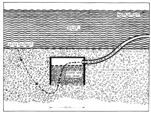
Fig 7. Diagram of SWS Box Unit and Water Flow
![]()
![]()
![]()