![]()
![]()
![]()
SCSP-SFDC/77/AEn/CP16
by
L. Denila
Western Visayas Federation of Fish Producers, Inc.
Iloilo City, Philippines
1. INTRODUCTION
The construction of brackishwater ponds started in upper level portions of swamps reached by tidal waters. This was the most economical portion of the swamp area to develop because it did not require very high dikes due to its higher elevation. Fishpond owners did not need to use conveyances like rafts and bancas, which evolved later. The digging blades for excavation were short, very light and thin.
In time, due to pressure of population and the need of man for more food, fishpond areas progressed to the lower portions of the swamps and this required higher and stronger dikes. Likewise, better methods were devised for dike construction, particularly involving the use of rafts and dugouts. Digging blades were made longer and heavier because they were required for work under water in order not to lose time during high tides.
From the beginning, many of the fishponds, particularly in Iloilo, were started by family hands and whenever they constructed dikes in creeks they used the “bayanihan” (community) type of labour. Building of dikes across rivers was not resorted to because of the risks involved. Salaries paid to workers were in the form of cash, but sometimes in kind, such as rice and corn.
Encouraged by the experience of pioneering families, capitalists emerged, and constructed fishponds covering larger areas in even deeper portions of the swamps, where many of the former operators failed due to more costly requirements for dikes.
Those who had some practical engineering knowledge, instead of investing in deep portions of the swamp, bought out areas with higher pond bottom elevations and started excavating and levelling these areas for the purpose of growing more fish food, particularly the filamentous green algae.
In the process of levelling, these farmers thought of lowering the cost of construction, and so the flat boat came about. Further encouraged by the results of levelling because of better production, the more advanced farmers devised better techniques or systems in handling and conveyance of soil to further cut down the cost of construction.
Based on these facts, we can conclude that the practice of fishpond engineering as done by our forefathers depended on the requirements and situations existing in the swamps.
The lower elevation swamps, draining to the sea, needed modified equipment and techniques, than in the upper elevation areas. Thus, some practices of fishpond engineering as practiced today are evolutions of old traditional methods.
1.1 Dike construction
Dike construction workers have their own work organization. They work as a team and are composed of the following (Illustration No. 1):
Piler - who is responsible for placing the soil along the dike line and sees to it that the dimensions of the dike are maintained. He is also responsible for making the slope of the dike correct, to make it strong. He is a skilled worker.
Digger - who digs the soil in cubed form. He sees that the soil does not disintegrate during its transfer from excavation to the dike construction area. He is a skilled worker.
Raft or banca pusher - who pushes the conveyance boat to the dike construction area; unloads the cubed soil at the damping base. He may be skilled worker or unskilled.
Carrier - who receives and passes the cubed soil to the piler for proper laying. He is a skilled worker.
1.2 Dike construction system
1.2.1 Line system
Workers form a single line, each at least 2 metres apart. Their line extends from the source of the soil to the dike construction site. Soil in cubed form is relayed to each man until it reaches the piler. This system is considered the most expensive when the source of soil is a considerable distance from the dike, thus requiring more men (Illustration No. 2).
1.2.2 Sliding system
A sliding board is placed perpendicular to the dike line. The labourers throw the cubed soil on the board letting the soil slide down to the base of the dike. Although considered labourious, this system is very common where the source of soil is near the dike line, and is considered economical because it saves the fishpond operator from hiring an additional 2 to 3 workers (Illustration No. 3).
1.2.3 Raft system
This system is useable only during high tides. During high tide, a bamboo raft is filled with soil, and then pushed towards the dike construction area. At the base of the dike, the raft is flipped over. This system is easy for the workers, but expensive because the bamboo raft has only a small load capacity (Illustration No. 4).
2. THE NEED FOR IMPROVEMENT
New techniques and methods are now implemented as a result of engineering studies. Even specialized machinery is now available which can provide a new horizon in the fishery industry.
Fish farmers are always seeking ways and means to lessen their cost of construction. However, highly mechanized fishpond construction nowadays commands costs beyond the reach of an ordinary fishpond operator for the following reasons: (i) machinery is very costly, thus requiring high initial capital investment; (ii) the cost of operation is also high due to costs of fuel and spareparts. These factors have led to improving the manual system of pond construction, which also provides a social benefit by providing employment.
2.1 The flatboat method of transporting soil
At present some fishpond operators are using a “flatboat” instead of an ordinary banca or bamboo raft, as one means of improving construction efficiency. With the flatboat, the working system was also improved and this has resulted in lower construction costs (Illustration No. 5).
Each man is provided with one flatboat. He digs the soil and fills the flatboat to its maximum load. Then he pushes the flatboat towards the dike construction area. Upon reaching the base of the projected dike, he tilts the flatboat upside down until the last cubed soil is dumped. He then goes back to the soil source and excavates the soil for the next cycle. At present the flatboat method is considered the best for soil handling because:
it does not require too much effort to load;
it is very maneuverable;
it's construction is simple;
it is easier to tilt and dump the soil;
it requires minimal maintenance - only periodic tar painting.
The advantages of using the “one worker for one flatboat” system are:
one skilled worker with one flatboat can finish a dike with a volume of 7 m3 in 9 hours;
the worker has more incentive to work harder because he does not have to share wages with another worker;
there is no work discrimination.
The disadvantages of other manual systems with workers in groups are:
gang of workers can place only 3.5 m3 of dike for each individual in 8 hours, instead of 7 m3 for the one man one flatboat system;
work discrimination arises.
3. CONSTRUCTION OF FISHPONDS ON NEW SITES IN VIRGIN SWAMPS
3.1 Pre-construction requirements
Map of area, topographic map, ecology studies, watershed, hydrographic and soil surveys
Layout plans, design for pond bottom elevations
Cost estimates
Programme of work
Preparation of equipment and supplies
Construction of workers quarters (temporary)
Transportation facilities: (i) personnel, (ii) equipment; (iii) water and other supplies
Communication system if possible
Medical and first aid facilities
3.2 Actual construction (described in order)
3.2.1 Clearing for passage ways of main and secondary dikes
This is done by cutting the trees along a 5-metre strip for establishment of the base lines and dividing into stations. The volume of soil must be computed for each station and recorded in the ledger with the following information:
Cross-section of the dike, showing the length, width, height and total volume of the station;
Name of the worker
Price
Withdrawals
Station number
Date started and date finished
Remarks
3.2.2 Damming and closing of rivers and creeks (Illustration No. 6)1
Construction of the perimeter dike starts from closing of rivers and creeks, if there are any, to avoid washing out of the dike, since the flow of water becomes stronger when done at the last stage of the main dike construction.
Damming or closing of rivers and creeks can be risky, especially during the flood season. Dumping of soil is started in the deepest portion usually at the middle of the river and goes toward the shallow portion. The base should be wide enough to protect the dike from being washed away.
Wooden or bamboo stakes may be piled in staggered position if the current is strong. Allow the soil to harden on top before adding another layer. It takes time and several layers until the dike is ready for use.
The best time for this job is during the months of February and March when spring tides are normally lower than in the rest of the year and when floods do not occur. It is on this job that flatboats can be very economical.
1 Closing of creek is done only if legal and would not have adverse environmental effects
3.2.3 Construction of main and secondary dikes
After completing construction of dikes across rivers and creeks, construction of the rest of the main dike starts from the lowest portion of the channel and progresses towards the higher portion. This is shown in the topographic survey, and can be checked visually during during the recession of tide. The last portion to be exposed is the lowest.
When constructing the main dike, the flatboat is used during high tides only. Other systems as described in the previous section are used during low tides.
Secondary dikes and canals may be constructed while the main dike is being constructed.
The main gates may be constructed while construction of the main dike progresses, but this can be expensive because both ends of the gate will need higher temporary dikes. It will be less costly if done after the construction of the main dike is completed. The same is true of the secondary gates.
3.2.4 Clearing of vegetation
After the perimeter dike is enclosed, clearing of trees inside the pond can be expensive if the owner is in a hurry, that is he uses chain saws in cutting the trees.
For reasons of economy, a bit of patience is needed. The system is to let water in to as high as possible and then hold it. This height is maintained for six months, after which the leaves of the trees fall in the water, decay and serve as food for crabs, shrimps and other fish. While waiting for the tree trunks to dry, the pond can be stocked with fish, although not in large quantity. The trees, when dried, can be cleared by burning.
3.2.5 Pond levelling by flatboats
Pond levelling is a final and a costly item in the construction of fishponds. As a matter of fact, this is the main reason why some ponds do not produce as much as they should because some operators think that construction of fishponds is finished after the main and secondary dikes have been constructed.
Levelling the pond just after the dikes are constructed is very expensive. It is advisable to wait for 2 to 3 days until the root systems of the trees have partially decayed before levelling is started. This will lessen the capital outlay. Partial levelling may be done just after enclosure, but excavation should be limited only to portions where there are no trees. The soil excavated should be dumped in low portions that can not be drained. After 2 to 3 years, final levelling can be completed.
Assuming that a topographic survey has been made, the pond bottom elevations set, and the volume of soil to be cut and the portions to be filled have been determined, the following steps should be undertaken:
Bring the water down to the desired pond elevation and place a bench mark. Beside the bench mark place another stake about 7.5 cm wide, 2.5 cm thick and 2 m long, marked from 0–100 cm. This is the gauge for depth of water. The zero mark should be level with the bench mark which is the designated pond bottom elevation. This indicates the depth of water and serves as a levelling guide during filling.
Establish stations by marking principal locations above the zero elevation mark.
Let water in to a depth of about 40 cm so that the flatboats are afloat and start excavation. All vegetative cover is stripped and loaded to the flatboats and wasted outside the pond. The standard length for one “pasada” (handle length) of the digging blade is 30 cm so that if the handle is placed in the water and the ground level is 15 cm above the zero mark, 50 percent of the handle length should be excavated. In areas of extensive excavation the soil can be loaded directly on flatboats and placed in the dikes, or in locations below 0 0 cm elevation. The remaining soil on either side can be levelled easily using spades. One to two workers should be at the receiving end to supervise the dumping of soil in the deep portions; each receiver holds a metre stick to determine the depths by sounding and can supervise 20 flatboats.
When all marked portions have been excavated, bring down the water to 0 elevation. With the use of a spade the final levelling can be done.
The process is repeated until all lower portions are filled.
Excess soil is placed on the dikes as reinforcement.
During the final levelling, with the water at elevation 0, all water pockets should be connected by small canals.
3.3 Cost estimate of constructing a 10-ha fishpond in a virgin swamp (under Philippine conditions, particularly in Iloilo province)
| (a) | Pre-construction expenses | |
| Topographic area and other surveys |  3 000 3 000 | |
| Design and preparation of plans | 1 000 | |
| Total | 4 000 | |
| (b) | Equipment | |
| - Construction of 20 flatboats at 500 | 10 000 | |
| - 20 pieces digging blades at 40 | 800 | |
| - Materials for the construction of temporary houses of workers (labour supplied by workers) | 1 000 | |
| - Lumber for walking boards and for sliding | 800 | |
| Total | 12 600 | |
| (c) | Miscellaneous items such as medicines and other basic household items | 500 |
| (d) | Actual construction costs | |
| - Clearing of passageways for main and secondary dikes | 2 000 | |
| - Main dike construction, 24 500 cu.m at 4/cu.m | 98 000 | |
| - Construction of secondary dikes, 3 000 cu.m at 2.80/cu.m | 8 400 | |
| - Excavation for fill 2 500 cu.m at 2.80/cu.m | 7 000 | |
| - Pond levelling + 3 cm from the designed pond bottom elevation at 1 000/ha | 10 000 | |
| - Cutting and clearing of trees by burning at 500/ha | 5 000 | |
| - Construction of main and secondary dikes | 12 000 | |
| Total | 142 400 | |
| SUMMARY OF COSTS | ||
| (a) Pre-construction expenses | 4 000 | |
| (b) Equipment and materials | 12 600 | |
| (c) Miscellaneous | 500 | |
| (d) Actual construction cost | 142 400 | |
| Total | 159 500 | |
| (e) Contingency 10% | 11 950 | |
| GRAND TOTAL | 171 450 | |
| US$ 23,3271 |
BASIS FOR THE ABOVE ESTIMATE AS SHOWN IN THE PLAN
Basis of estimate for cut and fill
NOTE:
Average daily earning of one average local worker is not less
than 10 for 8 working hours. This will be more if the worker
comes from a far distance, much more from other provinces.
All elevations are based on mean lower low water (MLLW)
3.4 Factors affecting cost of construction
The cost of constructing a fishpond depends on several factors.
3.4.1 Range of tide and average natural elevations
A fishpond constructed in places with a high tidal range and whose average natural elevation is much higher than the desired pond bottom elevation will need more excavation work, while an area with low elevation will need higher dikes.
3.4.2 Topography
Levelling area with uneven topography is expensive.
3.4.3 Vegetation
An area covered with a thick growth of trees will be costly for clearing and levelling. If the cover is mostly of Rhizophora family, the root system of these species are very dense and when used as dike material, make a weak dike. This species also takes a longer time to decay under pond conditions.
3.4.4 Availability of manpower
If manpower is not available locally, the cost of construction increases if workers are imported.
A swamp having naturally flat topography and with an elevation at an ideal tidal elevation will be the least expensive to convert into fishponds.
4. CONCLUSIONS AND RECOMMENDATIONS
Manual labour is still the major means of pond construction and will be until such time as suitable mechanized equipment, which can be used at reasonable cost, comes on the market. The cheapest labour comes from local residents living near fishpond areas; therefore, it is advisable to train these people to work in fishponds as a source of ready manpower.
The system which promises to be the most economical is labour and machines, because there are portions of the job that can be handled more easily by machines. The use of hydraulic cranes in combination with flatboats lowers the cost by using the crane to excavate the soil and the flatboat to transport it one. There is no doubt that cranes can be used for construction in new sites in the construction of dikes, excavation and pulling stumps of trees.
The following factors should be considered when the manual system of construction is used.
Incentive - the most effective incentive is the amount that the owner pays for a certain job. This is a simple thing. If the basic needs of a worker such as food, shelter, clothing and elementary education of his children are satisfactorily achieved, the worker will continue working except during the planting and rive harvesting seasons. Otherwise, if workers are not given proper incentives, work will stop.
Equipment - if equipment is used, production capacity of an individual worker is increased.
System - in this system one individual worker for each flatboat, so far gives the best results if the job is on a contract basis.
4.1 Improvements
4.1.1 Increase the size of flatboats in width and length to increase their carrying capacity. The popular size of flatboats using 4 pieces of marine plywood ½" × 4'×8' can carry 1 cu m of soil (Illustration No. 7).
(a) Features of former types
New features
4.1.2 Design better digging blades to increase the cycle time for cubing.
4.1.3 Work in groups must be reduced or eliminated to encourage competition among workers.
4.1.4 It is possible that instead of pushing flatboats they could be pulled by a rope, or pushed by an outboard motor.
4.1.5 A water jet with a strong pressure could be used in levelling. A winch could be operated by one man.
4.1.6 Hydraulic cranes could be used for pulling tree stumps.
4.1.7 A hand tractor could pull a small leveler.
4.1.8 Mud pumps or a dredge could be used for levelling.
4.2 Additional recommendations
4.2.1 Equipment (Illustration No. 8)
digging blades (a) tagad, (b) osod
Former blades were
New improvements
4.2.2 Flatboat (Illustration No. 9)
Pull system
Former features:
New features
Sliding board
Former features
New features
4.3 Pointers in dike construction - malpractices
A profile of dike construction malpractices is shown in Illustration No. 10. The worker drops cubed soils along the way towards the dike construction area. This is being done to lessen the worker's burden in carrying the soil and piling it on the project dike line. The other illustration shows how the worker “cheats” by digging only the portion of the elevation of the pond bottom and not the proposed depth of excavation as agreed upon. This is commonly done when workers are paid in linear measurement of excavation and not by the volume of the dike.
Another malpractice to watch is shown in Illustration No. 11. The workers deliberately “sandwich” logs inside the dikes for the following reasons:
it requires less volume of soil for construction, but dike measurements are maintained;
the worker's services will be needed frequently for repairs due to seepage, instead of once every 2–3 years.
Effects
in time, the inside portion of the dike becomes a void when the logs starts rotting;
the hollow portions serve as passages for water to seep out;
crabs and other crustaceans will make it a haven.
Malpractices are now rampant in dike construction, especially the “pakiao” or “package deal” system. For example Illustration No. 12 shows the correct and incorrect ways of piling cubed soil. Under the incorrect way, notice the obvious gaps between cubed soil. These gaps in a short span of time will serve as a passage for water to seep out and in effect will reduce the normal volume of water available. Another reason is that the rains will easily destroy the formation due to loose compaction. And lastly, this is a form of “racket” by workers, because their services would be needed frequently, instead of once in every 3 or 4 years.
Illustration No. 13 shows the different forms of dikes:
Incorrect form of dike - this has been used as a “partition dike”. It has been a practice before, but due to constant erosion the system has been put out of practice and is no longer recommended.
Recommended form of dike - now the common form being constructed for “partition dikes”. It holds the soil longer and does not easily erode.
Recommended form of dike (double berm) - this is recommended if the two sides of the dike are exposed to wave action.
Recommended form of dike (single berm) - this is being recommended only if one side of the dike is exposed to wave action.
Illustration No. 14 shows the standard ratio of slopes being recommended.
Recommended slope for dikes which are less exposed to wave action - ideal for partition dikes.
Recommended slope for dikes more exposed to wave action -ideal for main dikes.
ILLUSTRATION NO. 1
(5) FIVE WORKERS WORKING IN GANG IN POND WITH WATER
ILLUSTRATION NO. 2
ILLUSTRATION NO. 3
ILLUSTRATION NO. 4
ILLUSTRATION NO. 5
ONE MAN-ONE FLAT BOAT OPERATION
ILLUSTRATION NO. 6
CLOSING OF RIVER OR CREEK
ILLUSTRATION NO. 7
DETAIL OF FLAT BOAT
ILLUSTRATION NO. 8
EQUIPMENTS FOR EXCAVATION
ILLUSTRATION NO. 9
ILLUSTRATION NO. 10
ILLUSTRATION NO. 11
THIS FORM OF CHEATING IS MADE BY CONTRACT “PAKIAO” WORKERS IF PAYMENT IS BASED ON VOLUME OF SOIL MEASURED ON THE DIKE.
WATCH OUT FOR DELIBERATE LAYING OF TRUNKS OF TREES BY CONTRACT WORKERS ("PAKIAO) PUNPOSELY TO CHEAT FISHPOND OWNERS.
ILLUSTRATION NO. 12
THIS FORM OF CHEATING IS MADE BY CONTRACT “PAKIAO” WORKERS IF PAYMENT IS BASED ON VOLUME MEASURED ON THE DIKE
ILLUSTRATION NO. 13
FORMS OF DIKES
ILLUSTRATION NO. 14
RATIO OF SLOPE 1:1
A * RECOMMENDED RATIO OF SLOPES FOR DIKES WHICH ARE LESS EXPOSED TO WAVE ACTION.
RATIO OF SLOPE 1.5:1
B * RECOMMENDED RATIO OF SLOPE FOR DIKES MORE EXPOSED TO WAVE ACTION.
SCSP-SFDC/77/CP29
by
M. Yamashita and Sutardjo
IDA Fisheries Credit Project
Directorate General of Fisheries
Jakarta, Indonesia
1. INTRODUCTION
1.1 Importance of proper engineering to industry
Brackishwater pond culture in Indonesia covers an area of about 186 000 hectares in total. It should be admitted, however, that many aspects both from the viewpoints of pond engineering and pond management still have to be properly improved and developed.
The Government has been aware of the need for developing the country's brackishwater pond culture potential, and some steps have been launced since the last few years. Methods of intensive brackishwater culturing operations have been introduced to farmers of the brackishwater pond centres, which include:
the improvement of the pond layout and construction design;
the use of pesticides for pest elimination;
the application of both organic and inorganic fertilizers; and
the milkfish and shrimp stocking.
Providing with proper schedule of culturing operation and proper improvements of both construction and pond management, to increase the level of production up to 1 000 kg/ha/year, as shown in Tables 1 and 2, is not difficult to be realized.
1.2 Status of industry
As can be seen from Table 3, the contribution of brackishwater pond culture to the total fish production in culture during the last ten years ranges from 37.5%–47.8% or on an average of 42.2% of the total. The total production of the brackishwater pond culture is 78 776 metric tons and amounted to Rp 51 376 385 in value1
1 Rp (Indonesian rupiah) 415 = US$1
In respect to the national average production, it is still very low, ranging from 252.9 kg/ha/year to 431.2 kg/ha/year or on an average of 336.6 kg/ha/year (Table 4). Nevertheless, the level of production is not the same from place to place, depending on local conditions, it varies from 300 kg/ha/year to 800 kg/ha/year.
The species which has been widely cultivated in the pond is the milkfish (Chanos chanos), but due to high market price, the tiger shrimp culture has been recently introduced in South Sulawesi and East Java, and the white shrimp in Aceh, showing promising results. The milkfish and Puntius gonionotus mixed culture is popularly practised in East Java.
In suitable pond condition, the growing rate of the tiger shrimp is fast, it will reach 30–70 g from fry during 3–5 months rearing period. Some farmers stock the ponds with the fry at the rate of 7 000 to 20 000 fry/ha/season. The survival rate is between 30–60% and the production varies from 100 kg/ha/season to 300 kg/ha/season.
The growth rate of the white shrimp is relatively slower compared with that of tiger shrimp. At present, the farmer usually stock the pond (collection pond) with the natural fry which enter the pond with the inflowing water during high tides. After one month, they reach 1.0–1.5 g in body weight and they are then removed to the rearing pond. Some farmers have already produced about 500 kg/ha/ season (100 days) shrimp of medium size or about 1 500 kg/ha/year in three rearing periods.
Regarding the species being cultivated, the brackishwater pond culture in Indonesia may be conveniently divided into:
milkfish monoculture;
milkfish and tiger shrimp mixed culture;
tiger shrimp monoculture;
milkfish and white shrimp mixed culture; and
milkfish and Puntius gonionotus mixed culture.
2. POTENTIAL
2.1 Brackishwater pond culture distribution
The distribution of the existing brackishwater pond culture is limited to three islands as shown in Table 5. Of the total 186 000 hectares of ponds, 96.3% are located in Java, South Sulawesi and Aceh, namely: Java, South Sulawesi and Aceh are respectively 63.6%, 24.1% and 8.6% of the total.
The potential sites for the extensification of the brackishwater pond culture are mostly located outside Java and it is roughly estimated about 6 000 000 hectares. The areas for immediate utilization are in Lampung area, where almost 7 000 hectares of swampland have been especially designated for pond development. Potential areas are also found in Aceh, North Sumatra, South Sulawesi and East Kalimantan.
2.2 Milkfish fry supply
The exploited milkfish fry fishing grounds are also limited to these areas as can be seen in Table 5. Of 617 000 000 fry produced in 1974, for instance 399 000 000 fry or about 65.0% were caught in Java. The fry production in South Sulawesi and Aceh are respectively 19.1% and 3.1% of the total. The potential areas of milkfish fry grounds outside these areas as yet have not been exploited.
The natural shrimp fry resources consisted mainly of the white shrimp and the next is the brown shrimp (Metapenaeus sp.), while the tiger shrimp fry is relatively small in quantity in most coastal areas. The kinds of natural shrimp fry entering the pond is estimated to be composed of white shrimp (70%), brown shrimp (25%) and tiger shrimp (5%).
The collection grounds of the tiger shrimp fry are found in some areas in South Sulawesi (along the coast of Pinrang, Takalar, Jeneponto) and in East Java (along the coast of Tuban and Banyuwangi).
2.3 Tidal conditions
The tidal conditions of five important locations are shown in Table 6. The tidal difference in East Java (53 517 ha), Aceh (16 600 ha), South Sulawesi (44 786 ha), Central Java (25 710 ha), and West Java (39 480 ha), are respectively 260 cm, 170 cm, 120 cm, and 80–100 cm.
In respect to the farm managing of the brackishwater pond culture in these areas, of 179 000 hectares of existing brackishwater ponds, 114 903 hectares or 64.5% belong to suitable tidal difference (120–260 cm) while the rest amounted to 64 690 hectares or 36.0% belong to less suitable tidal difference (80–100 cm).
Relying merely on the present natural conditions and the availability of the fry in the related areas, the species which are suitable to be cultured may be seen in Table 7.
3. SELECTION OF SITE
Important factors which should be included in the criteria as guidelines for selecting site are:
3.1 Site characteristics
3.1.1 Vegetative cover
Vegetative covers (Avicennia sp., Rhizophora sp., Nypa sp., etc.) of the coastal swampland selected should be light. The area which is so densely covered by the trees, especially the nipa, should be avoided as it will need high clearing cost which will make it economically unacceptable.
3.1.2 Land elevation
The site selected should have an elevation such that during high tides the water above the unexcavated area reaches 40–50 cm in depth, with 30 cm as the minimum required culture depth.
If the pond is constructed on higher level ground, the floor of the pond may dry up during the dry season, so that the fish have to be kept in the ditch.
To operate such a pond year around seems impossible because of insufficient water. To make such a pond fully utilizable, some means of getting water, either brackish or fresh, will be necessary. The use of a water pump or improvements of the whole irrigation system of the area may solve the problem.
Excess excavation of the land will not only increase the construction cost, but is also risky, as the lower layer potential acid-forming soil, has been observed in certain areas. A pH lower lower than 5.0 should be considered unsuitable and may endanger fish life.
3.1.3 Topography
Flat coastal swampland area is preferable for brackishwater pond culture as it minimizes the levelling expense.
3.1.4 Soil condition
The soil condition of the area plays an important role in view of its fertility and porosity. The pond is preferably constructed in soil of alluvial origin, which has at least 30% clay. The deltaic area is the most favourable condition for the development of the pond. Sandy areas should be avoided as it will be low in its production and it will make it difficult to control the water level of the pond due to dike leakage.
3.1.5 Water condition
The desired range of salinity and water temperature of milkfish is 5–30 ppt. and 27–30°C, while for shrimp it is 10–25 ppt. and 28–31°C.
3.2 Tidal difference
Relationship of tidal difference to their suitability for brackishwater pond culture, especially applied to the country's condition, may be tentatively grouped as follows.
1.0 m or less - Is considered to be unsuitable for managing the fishfarm as it is difficult for efficient filling and complete draining of the pond, including draining the peripheral ditch (examples: West and Central Java).
1.0 m – 1.5 m - The most suitable condition for milkfish culture and to a certain extent for shrimp culture (example: South Sulawesi).
1.5 m – 2.5 m - The most suitable tidal difference for both rearing of milkfish and shrimp. Filling and complete draining and drying of the pond, including the peripheral ditch and canal will not be a problem. The pond preparation before stocking can be properly carried out and high fish production can be expected. (Example: East Java, Aceh).
2.5 m or more - Will need stronger and higher dikes which will increase the construction cost and will make it economically unacceptable. The area is therefore unsuitable for brackishwater pond culture development.
3.3 Seed supply
The stocking materials for the brackishwater pond culture rely only on the natural fish fry and it is of importance to include the seed supply in the criteria for selecting a site.
4. TYPICAL LAYOUT OF POND
The typical layout of brackishwater pond is shown in Figures 1 and 2. It may be modified according to local conditions, which vary from place to place. Within the unit, the minimal requirements of compartments and their parts should be implemented:
nursery pond;
transition pond;
rearing pond;
water canal;
dikes (main, secondary);
sluice gates (main, secondary);
peripheral ditch; and
levelled pond bottom or platform.
4.1 Nursery pond
The nursery pond is small in size and is used for rearing the fry for about 30 days before being stocked into another larger pond. Rearing the fry in such a small area is safer and convenient as it can be closely watched and properly cared for. Usually after 30 days the fish food available in the pond begins to decrease, while the fish is still too small in size to be transferred to the rearing pond, and the fish is, therefore, removed to the transition pond.
4.2 Transition pond
The fish is reared here for another 30 days or more (stunted) before being removed into the rearing pond.
4.3 Rearing pond
The rearing pond is used for growing the fingerling size of fish up to marketable size. In more intensive culturing operation, the fingerling production may become a unit and separated from the production for market fish industry.
4.4 Pond bottom
The bottom should be of fertile soil, as it is the most important part of ponds for producing the natural fish food (benthic algae). The culture depth should be controlled so that sufficient sunlight can reach the bottom.
4.5 Peripheral ditch
The suitable ranges of temperature for milkfish and shrimp are 27.0–32°C and 28.0–30°C, respectively. During the dry season, the water temperature may increase, especially in the shallower part of the pond bottom, which can endanger the shrimp life. The peripheral ditch is constructed deeper than the bottom level, and it is useful for hiding place of the shrimp during a critical condition of the pond.
4.6 Water canal
The unit should be constructed according to the parallel system, in which each pond has its own gate. The canal is necessary for efficient filling and draining of the pond and it will also ease pond maintenance.
5. DESIGN AND CONSTRUCTION
5.1 Construction
The available brackishwater areas are not entirely within the range of ideal conditions with respect to the fishfarm management. This large potential area should be utilized to its maximum level of production.
5.1.1 Construction in area of low tidal difference
This type applies to West-, Central-Java and South Sulawesi conditions. The required pond water depth for rearing milkfish and shrimp is for instance 40 cm in the platform, 70 cm in the peripheral ditch and about 100 cm in the canal, and the pond is still able to be drained and dried up completely.
These requirements cannot be met in these areas, as shown in Figure 3. In West- and Central-Java, the maximum depth of water in the peripheral ditch is 60–65 cm and increasing the depth will make it difficult to drain the water from the ditch. The canal bottom level cannot be drained by any tide.
This is the minimum acceptable condition, in which complete draining and drying of the center of the pond is possible, although it is impossible for the peripheral ditch to be drained.
In such a condition pest control must be carried out by addition of pesticides to the standing water. Maintenance of the pond will be somewhat more difficult under such condition.
The use of a water pump is possible under such conditions, provided its technical and economical aspects have been considered.
5.1.2 Construction in area of suitable tidal difference
This type applies to East Java conditions. As seen in Figure 4, the central platform, peripheral ditch and canal can be constructed to conform with the levels of water required. The water levels here adjusted to 40 cm in the central platform, 100 cm in the peripheral ditch, which may be considered to be favourable for shrimp culture. The bottom level of the canal is 30 cm below the level of the peripheral ditch to make it easy for complete draining and drying of the pond.
Due to high water level during extra high tide and heavy rain, it will need high and wide dikes to prevent loss of fish during floods.
It will also need a big sluice gate, as shown in Figure 5, which has length, width and height respectively of 560 cm, 120 cm and 225 cm or more.
5.2 Specification
5.2.1 Milkfish pond
About 1–2 hectares is considered to be of convenience in respect to its operation and management. The depth of water on the platform is 30 cm as the minimum acceptable culture depth. The ratio of the nursery pond, transition pond and rearing pond is 1:9:90.
5.2.2 Shrimp pond
About 0.5–1.0 hectare is considered suitable for operating and managing shrimp culture. The range of condition suitable for shrimp culture is narrower than that of milkfish. The water depth required is about 40–100 cm.
5.2.3 Dike
The main dike should be constructed 40–50 cm higher than the highest tidal level experienced in this area. The width of top is 1.5–3.0 m, the base 3–5 m and the slope 1:1. For the secondary dike the width of top is 1.0 m, the base is 2–3 m and the slope 1:1.
5.2.4 Sluice gates and screens
Sluice gates and screens can be found in Table 8 and Figure 6.
5.3 Procedure of construction
Fix the standard marking pole at selected point of nearby stream or natural small canal.
Note the necessary data on:
the highest tide level experienced in the area
the lowest low tide on the area
Fix the main dike, secondary dike and canal points of each pond by poles (bamboo sticks) based on the construction plan.
Set up 30–50 bamboo poles at important points of the area and then mark on the poles the average high tide level (AHTL) which has been computed from the standard level.
From the AHTL line, fix the required pond water level and then compute and determine the pond, ditch canal bottom and the top of dikes.
Depending on these computations, deepening of pond, ditch, canal and dikes can be carried out.
Set-up all sluice gates and screens required by each pond.
6. REFERENCES
Directorate General of Fisheries, 1975 Fisheries Statistics of Indonesia
Jamandre, T.J. and H.R. Rabanal, 1975 Engineering aspects of brackishwater aquaculture in the South China Sea Region. FAO/UNDP South China Sea Fisheries Development and Coordinating Programme, Working Paper SCS/75/WP/16: 37p., 17 annexes
Table 1. Milkfish culturing operation in East Java (October 1976 – July 1977)
| Pond | 1976 | 1977 | Remarks | ||||||||
| O | N | D | J | F | M | A | M | J | J | ||
| NP | 70% | 28 days | Nursing from fry to fingerling size (28 days) | ||||||||
| TP | 85% | 30 days | Rearing the fingerlings before stocking to RP (30 days) | ||||||||
| RP(1st stocking) | 89.9% 122 days | Rearing from fingerling to marketable size (I) | |||||||||
| TP (stunting) | 56.3% 134 days | Keeping the fingerlings for the next rearing season | |||||||||
| RP (2nd stocking) | 88.2% 86 days | Rearing from fingerlings to marketable size (II) | |||||||||
| Pond | Rearing period | Stocking Harvest | Survival rate (%) | Rearing (days) | ||
| (No. fish) | (No. fish) | (kg) | ||||
| NP | 7/10/76–4/11/76 | 13 750 | 9 625 | 70.0 | 28 | |
| TP | 4/11/76–4/12/76 | 9 625 | 8 250 | 85.7 | 30 | |
| RP (I) | 4/12/76–5/4/77 | 3 300 | 2 967 | 873.0 | 89.9 | 122 |
| TP | 4/12/76–17/4/77 | 4 500 | 2 533 | 56.3 | 134 | |
| RP (II) | 17/4/77–12/7/77 | 3 400 | 3 000 | 1 000.0 | 88.2 | 86 |
| Pond size | : | 2.0 | Ha |
| Stocking rate | : | 13750 | fry |
| Rearing period | : | 278 | days |
| Production | : | 1873 | Kg or 946.5 kg/ha/278 days |
| Survival rate | : | 43.4 | % (from fry to marketable size) |
Table 2. Recommended dosage of various inputs per hectare per year
| No. | Item | Dosage |
| 1 | Organic fertilizers | |
| Rice bran | 1 600 kg | |
| Copra cake | 1 000 kg | |
| Cowdung, compost | 2 000 kg | |
| 2 | Inorganic fertilizers | |
| Urea | 2 000 kg | |
| TSP | 1 000 kg | |
| 3 | Pesticides | |
| Brestan-60 | 1 kg | |
| Derris root | 8 kg | |
| 4 | Supplemental feed | |
| Rice bran | 600 kg | |
| 5 | Seed | |
| Chanos monoculture | 10 000 kg | |
| Shrimp and chanos mixed culture | ||
| Chanos | 8 000 fry | |
| Shrimp | 10 000–20 000 fry |
Table 3. Fishery production in culture, 1966–1975
| Year | Production in culture (metric ton) | Production in brackishwater culture (metric ton) | Production in freshwater culture (metric ton) | 3/2 × 100% |
| 1 | 2 | 3 | 4 | 5 |
| 1966 | 134 001 | 54 067 | 79 934 | 40.3 |
| 1967 | 137 626 | 56 750 | 80 876 | 41.2 |
| 1968 | 116 118 | 43 528 | 72 590 | 37.5 |
| 1969 | 114 854 | 51 876 | 62 978 | 45.2 |
| 1970 | 134 602 | 55 908 | 78 694 | 41.5 |
| 1971 | 138 363 | 60 788 | 77 575 | 41.9 |
| 1972 | 131 208 | 51 203 | 80 005 | 39.0 |
| 1973 | 139 402 | 60 481 | 78 921 | 43.4 |
| 1974 | 146 809 | 66 756 | 80 053 | 45.5 |
| 1975 | 164 647 | 78 776 | 85 871 | 47.8 |
Source: Fishery Statistics, Indonesia, 1975
Table 4. Average production in brackishwater culture, 1966–1975
| Year | Area (ha) | Production (metric ton) | 3/2 × 1 kg |
| 1 | 2 | 3 | 4 |
| 1966 | 165 409 | 54 067 | 326.7 |
| 1967 | 165 007 | 56 750 | 343.9 |
| 1968 | 172 054 | 43 528 | 252.9 |
| 1969 | 177 061 | 51 876 | 292.9 |
| 1970 | 179 911 | 55 908 | 310.7 |
| 1971 | 182 073 | 60 788 | 333.9 |
| 1972 | 178 297 | 51 203 | 287.2 |
| 1973 | 184 090 | 60 481 | 328.5 |
| 1974 | 186 167 | 66 756 | 358.6 |
| 1975 | 182 701 | 78 776 | 431.2 |
Source: Fishery Statistics, Indonesia, 1975
Table 5. Brackishwater pond culture and milkfish fry production by area, 1974
| Area | Brackishwater pond culture | Milkfish fry production | ||
| ha | % | × 1000 | % | |
| Indonesia | 186 167 | 100 | 617 909 | 100 |
| Java | 118 207 | 63.5 | 399 674 | 64.7 |
| Java & South Sulawesi | 162 993 | 87.5 | 517 074 | 83.8 |
| Java, South Sulawesi & Aceh | 179 593 | 96.5 | 536 834 | 86.9 |
Source: Directorate General of Fisheries, Jakarta
Table 6. Yearly tide difference in 5 important brackishwater pond culture areas
| Province | POND AREA | YEARLY TIDE DIFFERENCE | ||||
| ha | % | Station | Max. (cm) | Min. (cm) | Difference (cm) | |
| Aceh | 16 600 | 9.2 | Sabang | 160 | 0 | 170 |
| West Java | 39 480 | 21.9 | Jakarta | 110 | 10 | 100 |
| Cirebon | 90 | 10 | 80 | |||
| Central Java | 25 210 | 14.0 | Semarang | 100 | 10 | 90 |
| East Java | 53 517 | 29.8 | Surabaya | 270 | 10 | 260 |
| South Sulawesi | 44 786 | 24.9 | Ujung Pandang | 130 | 10 | 120 |
| 179 593 | 100.0 | |||||
Source: Fisheries Statistics, Indonesia, 1975
Tide Tables. Indonesian Archipelago, 1977
Table 7. Recommended species to be cultivated by province
| Province | S P E C I E S | |||
| 1 | 2 | 3 | 4 | |
| West Java | Milkfish | W. shrimp | Others | - |
| Central Java | Milkfish | W. shrimp | Others | - |
| East Java | Milkfish | T. shrimp | W. shrimp | Others |
| South Sulawesi | T. shrimp | Milkfish | W. shrimp | Others |
| Aceh | W. shrimp | Milkfish | T. shrimp | Others |
NOTE: T. shrimp is tiger shrimp, Penaeus monodon and W. shrimp is white shrimp, P. merguiensis
Table 8. Number and specification of sluice gate and screen for one pond unit of 5.0 ha in size
| Species to be cultivated | Milkfish | Shrimp | ||||
| Width (m) | Height (m) | Number | Width (m) | Height (m) | Number | |
| Sluice gate for | ||||||
Main gate | 1.2 | 2.5 | 1 | 1.5 | 2.5 | 1 |
Nursery pond (NP) | 0.4 | 1.5 | 2 | 0.4 | 1.5 | 2 |
Transition pond (TP) | 0.75 | 1.5 | 2 | 0.75 | 1.5 | 2 |
Rearing pond (RP) | 0.8 | 2.0 | 4 | 0.8 | 2.0 | 4 |
| Length (m) | Height (m) | Number | Length (m) | Height (m) | Number | |
| Screens | ||||||
| Bamboo screen used as protector for: | ||||||
Main gate | 5.0 | 1.5 | 1×1 | 10.0 | 1.5 | |
Nursery pond (NP) | - | - | - | 6.0 | 1.5 | 1×2 |
| Bamboo screen for: | ||||||
Main gate | 5.0 | 1.5 | 1×1×2 | 6.0 | 1.5 | 1×2×2 |
Nursery pond (NP) | 3.5 | 1.5 | 2×2×2 | 3.5 | 1.5 | 2×2×2 |
Transition pond (TP) | 6.0 | 1.5 | 2×2×2 | 6.0 | 1.5 | 2×2×2 |
Rearing pond (RP) | 10.0 | 1.5 | 4×2×2 | 13.5 | 1.5 | 4×2×2 |
| Plastic net (mesh 1mm): | ||||||
Main gate | 5.0 | 1.0 | 1×2 | 6.0 | 1.0 | 1×2 |
Nursery pond (NP) | 1.0 | 1.0 | 2×2 | 1.0 | 1.0 | 2×1 |
Transition pond (TP) | 4.0 | 1.0 | 2×2 | 4.0 | 1.0 | 2×2 |
Rearing pond (RP) | 6.0 | 1.0 | 4×1 | 12.0 | 1.0 | 4×2 |
| RP | - Rearing pond | Main gate | |
| TP | - Transition pond | Secondary gate | |
| NP | - Nursery pond | (NP,TP,RP) |
Figure 1 - Typical layout for one management unit of 5 hectares
| RP | Rearing pond |
| TP | Transition pond |
| CP | Shrimp fry collection and catching pond |
Figure 2. Typical layout for white shrimp culturing pond (Aceh)
| MD | Main dike | Required water depth in: | |
| EHT | Extra high tide | ||
| AHT | Average high tide | Rearing pond | 40 cm |
| PBL | Pond bottom level | Peripheral ditch | 70 cm |
| PDBL | Peripheral ditch bottom level | Canal | 100 cm |
| ALT | Average low tide | ||
| ELT | Extra low tide | ||
| CBL | Canal bottom level | ||
Figure 3. Possibility of bottom level in area of low tidal range
| Required water depth in Rearing pond | 40 cm |
| Peripheral ditch | 100 cm |
| Canal | 130 cm |
Figure 4. Pond water depth in area of high tidal range
Figure 5 - Wooden gate construction (East Java)
Figure 6. Wooden sluice gates and screening system
SCSP-SFDC/77/AEn/CP19
by
S. Tamiyavanich
Chulalongkorn University
Bangkok, Thailand
1. INTRODUCTION
Thailand has a coastline of 2 614.40 kilometers. Most of the coastal areas are mangrove swamps which are suitable for aquaculture. At least 10 000 hectares have now been developed into ponds for culturing of highly valued shrimp, certain species of bivalves and some finfish. There are still at least 150 000 hectares available for further development. Pond culture in brackishwater around the coastal areas of Thailand has its origin not less than 40 years ago. Many brackishwater species being raised and tried out in aquaculture farms are as follows:
| (a) | Crustaceans | : | shrimp (Penaeus and Metapenaeus spp.) |
| mangrove crab (Scylla serrata) | |||
| (b) | Molluscs | : | arkshell clam (Anadara granosa) |
| mussel (Mytilus smaragdinus) | |||
| oyster (Crassostrea spp.) | |||
| (c) | Finfish | : | seabass (Lates calcarifer) |
| milkfish (Chanos chanos) | |||
| mullet (Mugil spp.) |
Among these, the culture of shrimps and molluscs are done extensively (Tables 1 and 2). As for finfish, the process is still in its experimental stage, even then its production is anticipated to meet the demand during the years 1973–1980 (Table 3). This report will cite one pond culture that has been done most extensively in Thailand, that is shrimp farming. There are two main methods in shrimp farming.
The original method was done crudely by raising the dikes around the former ricefield or salt farm in order to trap water that comes in during high tides especially spring tides. The water will then carry the larvae of shrimp, fish and other species into the farm. The larvae then will be kept and feed themselves naturally in the farm for a period of 45–60 days. At this point, the shrimps can be sold or consumed. The water in the farm will be let out during low tides and the field will be left to dry out until next spring tides. Later on the use of irrigation waterwheel was introduced to help regulate more water into the field, and thus increased the amount of shrimp larvae.
The new method differs from the old one in that the pond being dug to a depth of 1–2 metres with 1–2 irrigation gates. The pond is smaller than the field for easy care. The water was irrigated into the pond through a screen in order to get rid of undesirable species such as fish and crabs. Then, the shrimp larvae that were caught or cultured separately would be put into the pond at density of 15–20 specimens per square metre. They will then be fed with some fish meat or squid twice a day. The water would also be regulated everyday. Shrimp raised in this method will take about 2–6 months depending upon the original stage of shrimp larvae. The production of this method is very high.
2. SITE SELECTION
Criteria used in site selection are as follows:
2.1 The site must be situated at a place where: - seawater is easily accessible; water must be clean and free of pollutants especially those from the industry; and its salinity does not vary greatly.
2.2 The soil must be of clayish type for it makes very strong dikes and retains water well. In addition, in selecting the type of soil, the species of shrimp intended for rearing must also be taken into account. For example, Penaeus merguiensis and Metapenaeus ensis grow well in muddy bottom but Penaeus monodon and Penaeus semisulcatus grow better in sandy bottom.
2.3 The site must be high enough so it will not be flooded during the monsoon season, but not too high so it can be easily irrigated.
2.4 The area must have sufficient stock of natural shrimp larvae in order to reduce the problem of purchasing cultured larvae.
2.5 Finally, the site must have easy access to market and transport and hired help.
3. DESIGN AND CONSTRUCTION
Once the site has been selected the procedures are:
3.1 Survey the soil; measure the area and its level; check wind direction; measure level of high and low tides and the distance from the sea or irrigation canal.
3.2 Divide the area into raising ponds and nursing ponds. Usually, a farm of 20 rai1 size is preferable for easy maintenance. The length of the pond should be in the same direction as the wind so that the wind may circulate the water most effectively.
3.3 Pond should have two seperate water channels, one, coming in and the other going out.
1 rai is a measure of area in Thailand equivalent to 1 600 m2
3.4 The depth of the pond should be about 1.50 metres and not more than 2 metres because it will accumulate the sediment and reduce oxygen content at the bottom. Furthermore, it will be difficult to drain the pond in preparation for the next batch of larvae. Therefore, the bottom of the pond should be about 50 centimetres higher than the point of low tide for easy irrigation.
3.5 Dikes should be wide and strong and with gentle side slopes. To strengthen the dike and prevent leakage, gravel should be used mixed with the soil dug up from the pond. The width should be about 2 to 3 metres. There should also be a berm to prevent soil erosion in the rainy season.
3.6 Irrigation gates to regulate water in and out of the pond should be about 1 metre wide and there should be 1 to 2 gates for the farm of 20 rai size.
3.7 Once the decision on the size and shape of pond has been made, the process of pond construction can begin. The finished pond should be flushed with water several times to adjust and regulate the pH level in the soil. The best pH for shrimp farming is between 6.5 to 8.5 The pond is then left to dry out for 7 to 10 days. Then the process of shrimp farming can start.
4. MANAGEMENT AND MAINTENANCE
The management and maintenance processes are probably the most important, because they will dictate the degree of success in shrimp farming. If the owner pays close attention and keeps alert to new techniques, shrimp production will be higher than those run by hired hands.
Problems encountered in shrimp farming are as follows:
Water level is not high enough causing temperature of water to rise to a point that many shrimp larvae cannot survive. The rise in water temperature also cause shrimp to congregate in some deep pockets or channels in the field, causing the death of many smaller shrimps since they are cannibalistic. Therefore, the dikes on all sides of the field should be raised to create an average depth in the field of at least 1.50 metres.
Sometimes there is leakage around the dikes resulting in the loss of water. Therefore, the use of plastic sheets or some tiles to cover the holes may help improve the situation.
Shrimp predators such as sea bass, crabs and birds are quite serious problems. Some of these predators feed directly on shrimp; others take food and shelter away from the shrimp. To eradicate these predators, especially fish, saponin solution which was extracted from tea seed was applied directly into the pond.
There are many more problems in shrimp farming, to mention a few: shrimp feeds, diseases and parasites, which will not be included in this paper in detail.
5. OCNCLUSION AND RECOMMENDATION
Prospects of further expansion in shrimp farming cannot depend entirely on the supply of shrimp larvae from nature, because it fluctuates greatly and is also often unpredictable. The feasibility of the large-sacle culture of penaeid larvae has been demonstrated at the Phuket Marine Fisheries Station. Every experiment was designed to develop a method for increasing the survival rate and minimizing the initial costs of shrimp larvae production. Eventually an adequate supply of shrimp larvae can be ensured to shrimp farmers.
Although shrimp farming has been practised for quite sometime, the development of this industry has received the necessary enthusiasm only recently. Because of the demand for shrimp in both foreign and domestic markets, shrimp farming is relatively high, if only the farmers would look after it closely and be willing to accept and try out new techniques, shrimp farming could be a very productive and satisfying venture.
Table 1. Shrimp farms and their production during 1970–1974
| 1970 | 1971 | 1972 | 1973 | 1974 | |
| Total number | 945 | 1 200 | 1 154* | 1 462 | 1 518 |
| Areas used (rai) | 44 704 | 59 914 | 56 602 | 71 668 | 75 576 |
| Production (tons) | 975 | 954 | 1 450 | 2 060 | 2 926 |
| - shrimps | - | 911 | 911 | 1 365 | 1 775 |
| - fish | - | 43 | 459 | 695 | 1 151 |
| Values (+ 106baht) | - | - | - | 37.4 | 48.3 |
| - shrimps | - | - | - | 35.3 | 43.2 |
| - fish | - | - | - | 2.1 | 5.1 |
Table 2. Molluscan productions from the Inner Gulf of Thailand, 1971–1974 (in metric tons)
| Species | 1971 | 1972 | 1973 | 1974 |
| Oysters | 2 294 | 941 | 1 100 | 2 142 |
| Mussels | 208 918 | 70 991 | 10 710 | 12 962 |
| Arkshell clam | 10 461 | 2 706 | 3 920 | 1 494 |
| Others | 38 122 | 26 209 | 25 680 | 26 325 |
| Total | 259 795 | 100 847 | 41 410 | 42 923 |
Table 3. Projected demand and supply of fish production in Thailand, 1973–1980 (in metric tons)
| Estimated | SUPPLY OF EDIBLE FISH | |||||
| Year | population | Projected | Aqua- | |||
| (million | demand | Marine | Inland | culture | Total | |
| 1973 | 39.7 | 795 014 | 775 487 | 100 759 | 39 716 | 915 962 |
| 1974 | 41.0 | 832 254 | 780 000 | 100 000 | 55 128 | 935 128 |
| 1975 | 42.2 | 912 049 | 800 000 | 100 000 | 67 370 | 967 370 |
| 1976 | 43.5 | 954 770 | 800 000 | 150 000 | 80 780 | 1 030 780 |
| 1977 | 44.8 | 999 493 | 820 000 | 160 000 | 94 195 | 1 074 195 |
| 1978 | 46.3 | 1 046 310 | 850 000 | 170 000 | 107 610 | 1 127 610 |
| 1979 | 47.7 | 1 095 322 | 850 000 | 180 000 | 120 975 | 1 150 975 |
| 1980 | 49.2 | 1 146 555 | 900 000 | 190 000 | 143 240 | 1 233 240 |
6. REFERENCES
Chaloyandeja, K., 1977 Shrimp farming. Division of Brackishwater Fisheries, Department of Fisheries (Mimeograph)
Chotiyaputta, K., 1977 Problems in shrimp farming. Division of Brackishwater Fisheries, Department of Fisheries (Mimeograph)
Department of Fisheries, 1977 Aquaculture and marine resources potential and policy in Thailand. Division of Brackishwater Fisheries (Mimeograph)
Kungvankig, P., 1976 Early development stages of jumbo tiger shrimp (Penaeus monodon Fabricius) No. 6. Brackishwater Fisheries Unit, Phuket Fisheries Station
Terazaki, Makoto, et al., Eradication of predatory fishes in shrimp farms (Mimeograph)
SCSP-SFDC/77/AEn/CP31
by
Fisheries Division, Ministry of Agriculture and Land Reform
Kuala Lumpur, Malaysia
1. INTRODUCTION
The mangrove forest of Malaysia covers an area of more than 650 000 ha of which 112 000 ha are found in West Malaysia. Apart from their value as a source of timber, it is also a natural habitat for many aquatic organisms of commercial importance and are also recognized as an important potential sites for the development of coastal aquaculture.
Malaysia does not have a tradition of brackishwater aquaculture nor the experienced manpower for this industry. There is general lack of background and experience in brackishwater aquaculture in the country. The only form of brackishwater culture practised in Malaysia which has some economic importance is the shrimp pond trapping operations. Shrimp pond trapping operations which have been practised for quite some time are now being carried out on a profitable scale on the southern coast of West Malaysia. The operation and level of technique achieved in the trapping operations is by sheer trial-and-error. The more recent pond operators do make use of available data and apply modern technique in their ponds construction.
2. ENGINEERING CONSIDERATION OF SHRIMP TRAPPING PONDS
2.1 Method of operation
The shrimp trapping pond consists of a series of 30 to 50 acres (12 to 20 ha) ponds. Each pond is bounded by a system of dikes and flow control gates which regulate the water level in the pond in accordance with the tidal movement. The gates are opened during the incoming tide to fill the ponds. The inflow of water carries with it the juvenile shrimps and nutrients which are a source of food for the shrimp. Within the enclosure of the ponds the juvenile shrimps will grow to maturity under protection from predators and natural hazards as well as being sustained by supplementary feeding. Through this system of culture, the mortality rate of shrimps is minimized while the growth rate is maximized, resulting in more efficient utilization of the natural resource.
2.2 Conditions to be met
To operate this system of farming successfully, certain conditions have to be met as follows:
Out of these (i), (ii) and (iii) are points for consideration in the engineering aspect of trapping pond construction.
2.2.1 Topography of the area
Selection of area is very important in shrimp trapping pond operation. In-depth study of the natural water edge, mangrove formation, ground elevation and also the effects of tropical cyclones or severe winds. For example, extensive land development work in the watershed around the area will give the tidal stream feeding into the pond excess turbid water during rains. If the land elevation is too high based on tidal datum, the area would require some excavation to be used in the trapping operation.
2.2.2 Suitable soil for dike construction
Most of the trapping ponds are located where the soil is a recent alluvial deposit and is grouped into the Kranji Series. The soil is of low bulk density and shear strength and show large shrinkage in volume on drying.
2.2.3 Adequate tidal range
The operation of the shrimp trapping pond necessitates regular circulation and renewal of water in order to replenish the ponds with fresh nutrient and also to have substantial flushing action during harvesting. Since this is mainly dependent on tidal action a knowledge of fluctuation of tide levels at site is important in the design of ponds.
In most Malaysian shrimp trapping ponds, the necessary tide analysis not made during the early part of the pond construction. Through experience and by trial and error a reasonable degree of success is achieved in the shrimp trapping operation.
Most of the shrimp trapping ponds are located in the southernmost tip of Peninsular Malaysia in the state of Johor. In most cases, the following method of tide analysis is assumed:
Tide levels are predicted based on a standard port of Victoria Docks in Singapore (the nearest available place of recorded tide levels). The predicted tide levels at most of these shrimp ponds are assumed to be the same as that of Victoria Docks.
In the case of a pond location which is farther inland (upstream), then a proper tide level should be recorded at the nearest river gate as the fluctuation of water upstream changes within the range of tidal effect at the mouth. The discharge of the stream will also fluctuate with the tide levels in the area. Tide levels should be recorded for most of the months and the result will be not only important in determining the dike and pond construction, but also the number of days the pond can be operated.
By examination of tide recording in a typical area based in Figure 1 and by application of suitable correction factors, the following have been established.
| - tides are semi-diurnal | |
| - highest astronomical tide | (HAT) + 9.94 ft. (30.3 dm) MSL |
| - mean high high water | (MHHW) + 8.00 ft. (24.4 dm) MSL |
| - mean low high water | (MLHW) + 4.00 ft. (12.2 dm) MSL |
| - mean high low water | (MHLW) - 0.5 ft. (-1.5 dm) MSL |
| - mean low low water | (MLLW) - 1.5 ft. (-4.6 dm) MSL |
These figures are then used in the pond and dike construction.
3. PONDS
3.1 Size of pond
The size of a shrimp pond is decided on several considerations. Firstly, as a matter of operational requirement the pond area is determined by the velocity of the tidal flow which is utilized to flood the pond during seeding and to flush the adult shrimps into the nets during harvesting. In the seeding operation, the water bearing the juvenile shrimps and nutrients has to be evenly distributed over as wide an area as possible in the quickest time. But since the tidal velocity decreases over distance travelled, it will lose its effectiveness beyond a certain range. Therefore, if the pond surface is excessively large in relation to the given velocity of tidal flow, parts of the outer reaches of the pond will not receive sufficient seeds and nutrient and will become underproductive. In the same way, if the pond is too big the areas farthest away from the exit (gate) will not be adequately flushed so that harvesting is incomplete.
From the biological standpoint, to promote the best condition for growth, it is desirable to have more water in relation to the given shrimp population.
The economic ground for pond size selection is related to dike construction and pond management. It is often necessary to employ specialized machinery for excavation and dike building in a swampy environment and the heavy loads to be transported. Therefore, to make the proposition economically feasible, the pond to be constructed must be sufficiently large to justify the high cost for the use of machinery. Furthermore, a pond twice as big as two smaller ponds requires less perimeter bunding for the same pond surface area.
Also from the point of pond management, the most efficient utilization supervisory and maintenance personnel is achieved when the pond is of a certain size. It must not be too large to be beyond effective control nor too small to leave labour underemployed.
Based on all the above consideration, a pond size of 12–20 hectare is common in Malaysia.
3.2 Pond layout
Pond layout should give maximum area utilization and a pond complex does not necessarily have to have a geometric figure. Cut and fill should be at a minimum to reduce cost of construction. It is also necessary to do some river diversion or straightening to maximize area of ponds.
3.3 Pond levels
The elevation of the pond bottom in relation to the tidal range governs the frequency of exchange of water in ponds and also the quantity of earthworks for dike construction.
The depth of the ponds is to be around 1.1 m (3–½ ft.) as this depth has been found suitable for shrimp culture. There is also a possibility of undesirable hydrogen sulphide formation in ponds with deep waters.
4. DIKES
Perimeter dikes are constructed of excavated material around each pond. Typical details of the dikes based on data from Figure 1 are shown in Figure 2. Perimeter dikes are designed as follows:
height of dikes after settlement and shrinkage is at (+) 13.5 ft (+ 4.1 m) and is at least 2 ft (0.6m) above highest astronomical tide and maximum flood level
2:1 side slopes
12 ft (3.7 m) top width to accommodate light vehicular traffic.
a layer of sea sand is sandwiched in the dikes for stability and also to prevent crustaceans from burrowing holes
close turfing on exposed surfaces to prevent soil erosion.
5. WATER CONTROL STRUCTURES
The water control structures consist of 4 to 6 sluice gates for each pond placed at the most strategic position of the pond in order to get the maximum benefits from the tides. Most of the gates are made of concrete structures supported by bakau piles. A hardwood gate is used at the gate entrance to regulate the flow of water and a simple wooden handwinch is used to raise or lower the wooden water regulator.
6. CONCLUSION
Even though shrimp trapping ponds have been practised for some years in Malaysia, to many, it is a whole new concept in aquaculture. Only very recently that this method of brackish aquaculture attracted much attention due to its profitability.
Generally there is lack of background and experience especially in the engineering aspects of brackishwater aquaculture in the country. A great deal of studies and experimentation have to be carried out in this field, such as size of ponds, construction of dikes, water control structures, location, etc., to further increase the efficiency of shrimp trapping pond.
Note: 1 ft = 0.3048 m
Figure 1. Stage hydrograph of Sungai Gelang Patah at Timber Bridge (June/July 1975)
Figure 2. Typical section of shrimp trapping pond
SCSP-SFDC/77/AEn/CP10
by
E. V. Jamandre
Western Visayas Federation of Fish Producers, Inc.
Iloilo City, Philippines
1. INTRODUCTION
Milkfish culture in brackishwater ponds in the Philippines rely mostly on natural food for fish nutrition. To this extent, emphasis had always been stressed on the growing of plant and animal organisms considered to be choice food -filamentous green algae, lab-lab, plankton, etc. -as a preliminary step towards successful production. The role of fertilizer as an aid in the propagation of these foods was realized in the mid-1950's when yields of more than one ton of milkfish per hectare per year were achieved with the use of inorganic fertilizers.
The big demand for organic fertilizers started in the late 1960's when it was found that these, in combination with inorganic fertilizers, were major necessary inputs in the culture of lab-lab, a much more nutritious food than filamentous green algae. That this combination also created plankton blooms and high fish production was also observed in ponds where deep, low-salinity waters were maintained. The lack of organic fertilizers is now considered a big problem in the milkfish industry.
Solutions would be: (i) to raise sufficient poultry and livestock to supply adequate amounts of manure for one's requirements, (ii) to raise quick growing plants for their leaves like ipil-ipil (Leucaena glauca) to to be used as fertilizers or feed, and (iii) to utilize other available wastes from other sources - mills, factories, breweries, fields, etc. -which could be utilized as organic fertilizers.
Information from fishery biologists visiting other countries led us to decide on a piggery - milkfish culture integrated project. This was mainly from Dr. W.E. Johnson of the Pacific Biological Station, Nanaimo, B.C., Canada, who made the observation that in the Peoples Republic of China, about 15 pigs can adequately fertilize one hectare of carp pond. Later, cattle were introduced to get rid of grass overgrowths along the dikes, and to turn these into something useful.
2. POND LAYOUT, DESIGN AND CONSTRUCTION
The property which was acquired in 1967 covers an area of almost 120 hectares, made up of fishponds, ricefields and high grounds planted with coconuts and other cash crops. The fishponds, although producing milkfish, were poorly designed, underdeveloped, and shallow.
Renovation was immediately started, using a low ground pressure (LGP) D-4 bulldozer and back-hoe to construct dikes, excavate and level the pond bottoms, The layout (Fig. 1) was prepared with the assistance of Mr. Yun-An Tang, then FAO Milkfish Culture Expert in the Philippines.
The design was primarily for milkfish culture, thus the long supply canal for water management, holding acclimatization of the stock (Fig. 2). Grow out ponds are from 8 to 20 hectares. The nursery ponds are about 1.25 hectares each.
Excess soil were pushed to the main dikes. Portions of the perimeter dikes, particularly along the areas of former ricefields and high grounds are now almost 3 m (10 ft) high, with very wide slopes. All dikes are passable by motor vehicles - jeep, truck, tractor, etc. Extra soil were piled and made into a longitudinal strip of land about 60 m wide and 600 m long (Fig. 3).
Gates, both of the single and multiple door types, are of reinforced concrete. The main gates have been provided for installation of pumps (Fig. 4). The catch basin in front of the main sluice has concrete sides and bottom so that fish that are harvested are clean and fresh looking (Fig. 5 and 6). A concrete chilling tank completes the catch basin area.
To make dikes of permanent structures, concrete partition walls were constructed to separate the nursery ponds. Concrete acclimatization tanks were also built in front of the nursery pond gates (Fig. 7). A concrete catching pond for fingerlings was likewise installed (Fig. 8).
Erosion of the main dikes along the Jalaur River, main source of pond water, has been minimized by stone boulder rip-rapping and by emplacement of large individually constructed monoliths of boulders, by cement, where shore cutting is excessive. These function like tetrapods, engineering aids used against heavy wave action.
Packing of the soil materials in the dikes was achieved by passing the bulldozer tracks many times over newly laid layers as they are deposited. Also, dwarf coconut trees were planted along the sides to create a network of roots that would strengthen and hold the soil together.
The general elevation of the pond bottom is about 1.5 m above the mean lower low tide level. This is quite high, even in this section of the country which has relatively high range of tide (maximum of 2.2 m). Water adequacy during the months of February, March and April, when high tide levels are comparatively low, is a problem. During these periods, pumps have to be resorted to. A 24-inch propeller pump augmented by two 16-inch pumps operate sometimes continuously to provide enough water for fish culture purposes, keeping salinity at tolerable limits during days when evaporation is rapid, and to provide some aeration during periods of relative calm.
3. THE LIVESTOCK PROJECT
Ground breaking for the first unit of the piggery project was started in 1974. Two deep artesian wells had previously been laid to supply fresh water to the compound.
Built near the nursery ponds, the pens (Fig. 10), were provided with concrete flooring, canals and fixtures to drain the manures and sweepings and a digester to break down raw manure into safe residues before they are applied to the pond. Clear water effluent from the digester are directed to the nursery ponds. An extra bonus - methane gas - is tapped from the digester for cooking fuel purposes.
The second unit was set up on the raised island (Fig. 9). Two barns, containing all the requirements for efficient operation - sloping pens, demand drinking water system, following crates, etc., and another building for feed storage and processing were built. Lately, a digester and a four compartment treatment tank (Fig. 11) were added. The effluent from the last compartment can be directed through plastic hoses to six-grow-out ponds, totalling about 60 hectares.
At present, there are 134 sows and 8 boars comprising the “factory”. The sows are hybrids of Hypors, Yorkshires, Landrace, and Hampshire. Boars are pure breeds of the above. The total number of pigs is around 1 200, with plans to increase the stock to 3 000.
About 2.4 tons of feed are fed each day, at an average of about 2 kg per pig. Almost the same amount of manures are produced, all of which are applied either in treated or raw form to the pond compartments.
4. PROBLEMS AND CONSTRAINTS
When the ponds were deepened and leveled, practically all of the rich top soil were pushed to the dikes. Constant tamping by repeated passing of bulldozer made a hardpan of the bottom. Fish yields during the following years decreased and were very low.
Since the project was put up, fertilization of the grow-out ponds with raw sewage from the pig pens has, during the last three years, considerably improved the soil. Fish production is now gradually increasing. Plans are afoot with the operation of the sewage treatment tanks to raise milkfish in deep low salinity water with sustained low volume fertilization using treated effluents from both tank and digester.
We are still faced with some problems. From the piggery angle, they are:
Difficulty of transporting materials to and from the project. Iloilo City is about 16 km away. Supplies and materials have to be hauled over this distance, then transferred to boats to bring them across an inland river. The same is true with marketable pigs.
Availability of feed materials - we had preferred to formulate our own ration as we have felt that we could modify the feed from time to time to suit the needs of the animals. However, it has been observed that certain raw materials are quite hard to secure at times, and at others, although plentiful, could not be stored over long periods.
Very high initial capital investment - it is estimated that for every sow one keeps, one will spend 5 000 pesos for the animal and the facilities for keeping it and its litters. From our present operations, we have an average of 2.2 sows per hectare of ponds, which means an investment of about 11 000 pesos per hectare in terms of pigs and facilities for the piggery project.
For would-be investors, other problems would be:
Accessibility to the fishpond;
Availability of freshwater; and
Sufficient high grounds where the project can be established.
5. RECOMMENDATIONS
No doubt, an efficiently and scientifically managed piggery project will, on its own, pay off as a profit-making industry. The existence of large projects with thousand of heads of hogs attest to this. If this can be established in a brackishwater fishpond project, and if the manures would be fully utilized and used to improve and increase production, this added benefit should bring in more profit to the fish farmer.
Our observations have shown promising trends. But we had some reverses also. It appears that more studies should be conducted on how the wastes should be applied to produce maximum results. For while the experience in the People's Republic of China is on freshwater ponds, conditions in brackishwater pond system are much different. Once profitability, gauged against capital, time and risk is shown, the engineering requirements based on the above studies could be determined and filled.
Liberal financing, especially structured for this particular set-up should follow, with banks lending credit. Likewise, cooperative marketing should prevent price fluctuations and give the enterpreneur better returns from his investments.
Fig. 1. Layout of fishpond of Ernesto V. Jamandre, located at Zarrage, Iloilo, as prepared with the assistance of Mr. Yun-An Tang, FAO Milkfish Culture Expert (1965)
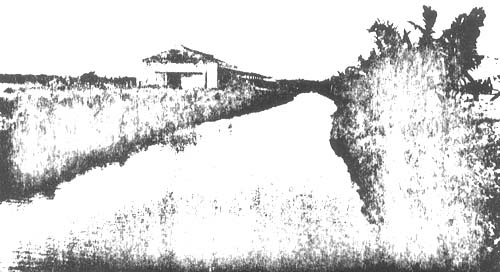
Fig. 2. Long supply canal for water management, holding and acclimatization of fish stock
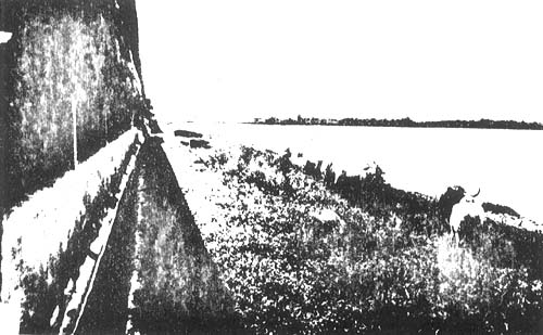
Fig. 3. Strip of man-made island, now site of the piggery project
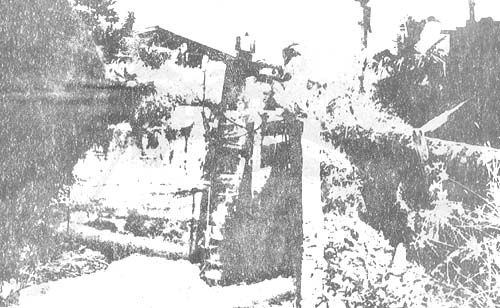
Fig. 4. Main sluice with a 24" propeller pump
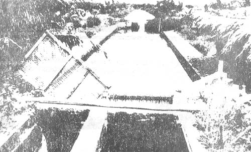
Fig. 5. Concrete catch basin in front of main sluice
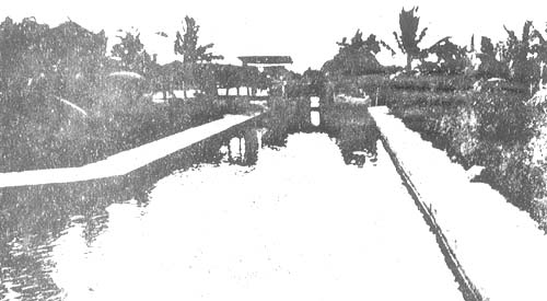
Fig. 6. View of catch basin towards the main sluice
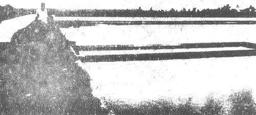
Fig. 7. Concrete dike and acclimatization tank of the nursery system
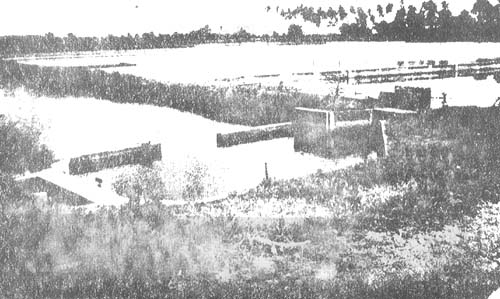
Fig. 8. Catching - holding pond for fingerlings
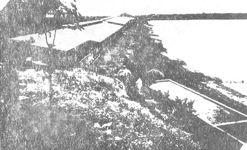
Fig. 9. Bird's eye view of second unit of the piggery project
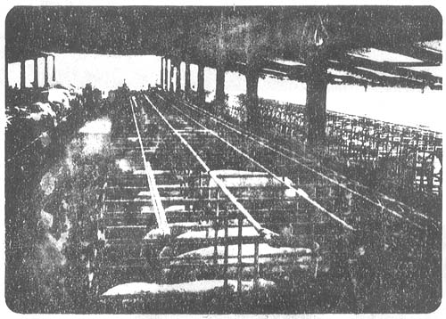
Fig. 10. Inside view of pig pens
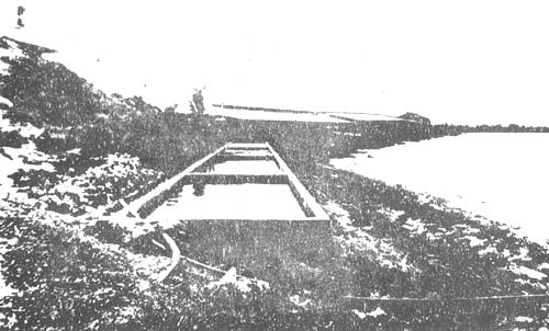
Fig. 11. Four compartment sewage treatment tank of the second unit of the piggery project
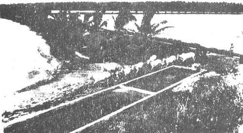
Fig. 12. Bird's eye view of portion of treatment. Note pond being fertilized and herd of cattle
![]()
![]()
![]()