![]()
![]()
![]()
RAW MATERIALS—
A wide range of materials can be used in extruded feeds, including high liquid content materials such as fish solubles. Cheap materials can even be used, but above all, it is important to use the highest quality materials which can be found.
FORMULATION—
Formulation = Nutrition x Feeds Technology
The formulator must understand the kinds of materials which are suited to extrusion. If this is done, it is possible to get good quality, low cost, palatable feeds.
GRINDING—
Extrusion needs finely ground materials. This reduces the energy cost of extrusion and reduces machine wear because materials flow better in the extruder barrel with less friction.
VARIABLES IN FEEDS EXTRUSION—
The Feeder-
The feeder rate needs to be calibrated for all products produced by the extruder. This can be done by measuring the amount of feed coming from the feeder over time. This should be done for different drive speeds (ie. maximum output; 75% of maximum; 50% of maximum; 25% of maximum).
The Conditioner-
The amounts of steam, water and oil added in the extruder can all be varied, as well as the time that the feed mash remains in the conditioner.
The Extruder-
The first thing that is needed is a well trained operator, who understands not only how to operate the machinery, but who also knows what is happening inside the machinery with the feed mash.
A single screw extruder does not have much versatility as only the screw pitch can be varied. However, twin screw extruders are very versatile. The number of steam locks can be changed, and the sections of the screw can be assembled to create a variety of forward and reverse kneading, mixing, pumping and conveying actions.
The amount of water and steam injected into the barrel of the extruder is very important. [A graphic plot of the density of a product versus the amount of water added during extrusion was shown. This feed was produced at a rate of 500 kg/hr, and contained 12% oil, 45% crude protein and 6% fiber.]
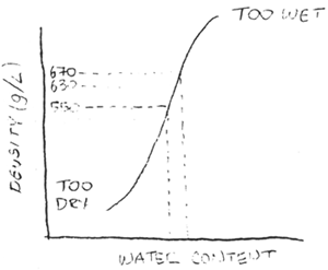
If the density of the feed produced is about 550 grams/L, all the feed will float in marine and fresh waters. If the density is about 630 g/L, feeds will sink in fresh water. If the density is about 670 g/L, feeds will sink in salt water. If too little water is added, the feed will fall apart. If too much water is added, a sticky wet product will result. The most important thing to note is that small differences in water addition of only a liter or two a minute can make a big difference in the density of the extruded product.
The temperature of the barrel can also be varied, to improve the degree of cooking of starch and protein in the feed. This cooking allows extruded feeds to have higher carbohydrate digestibilities than compressed pellet feeds.
Die selection is very important. A small number of holes results in large expansion of feeds, because of the high heat and pressure generated in the barrel. Surging, which is caused by irregular die pressure makes pellets of different length. The solution is to provide the operator with a large selection of dies — variety in the number of holes and the diameter of the holes — so that the right die can be selected for each formulation to make the best feed.
The cutter speed can be varied to change the length of the extruded pellets. the cutter knives are very important as well. Very sharp knives are needed. If knives are sharpened regularly, knife life before replacement will be longer. The angle between the cutter and die needs to be exactly 90 degrees. The knife blades need to be set flat against the die.
The best way to transfer feeds from the extruder to the dryer is to use vacuum suction. Variables in the dryer which can be controlled include the moisture of the product entering the dryer, the temperature of the dryer, the time in the dryer, the bed depth of the product in the dryer, and the moisture of the product exiting the dryer. Products from the extruder must dry slowly to prevent case hardening. Slow drying requires temperatures of 60–80°C. For materials which do not case harden easily, medium drying can be accomplished at 100°C. Invest in a moisture meter which the dryer operator can use to judge moisture in the feed exiting the dryer, so he can change dryer conditions quickly as needed.
BACK TO BASICS!
By Charles Botting
“I have become involved with
companies that have invested
hundreds of thousands of
dollars in a superb plant but
are unimpressed with the
operation or quality of
production.
More often than not the only
problem with the machine was
that nobody had thought to
sharpen the knives”
In my last article published in August last year entitled “Extrusion. An operators Perspective”. I outlined some of the problems associated with entering the extrusion business. Topics such as the type of machine, ancillary equipment and packaging, all essential questions that must be successfully answered before embarking upon the installation of an extrusion plant.
Since that time I have been surprised by the number of companies that have already invested considerable sums of money in plant that is either unsuitable, in that it is unfit for the operation in mind or, more often than not, operators or plant managers do not appreciate the flexibility of the machine they operate.
Here at home, with the prevailing economic climate many companies are reluctant to commit large sums of money towards new ventures or to speculate on a future in Extrusion, those that do have generally researched the subject in great depths before commitment.
Even so, plant that has been installed at great expense may not be utilised to its full potential, and in this article I hope to pin point some areas that are neglected.
Condition for success
Steam conditioning is just as vital to extrusion as it is to pelleting, although the benefits are not necessarily as immediately obvious in terms of product quality. But as with pelleting the immediate advantage of conditioning is a marked reduction in power consumption, in some cases reducing main drive power by as much as 20 per cent. The next long term advantage is a reduction in wear, particularly in the upper section of the barrel. It aids the expansion of the product, and this is of particular importance in certain countries where the pressure is on manufacturers to produce floating fish feeds (e.g. Korea where all fish feeds with the exception of prawn feeds must float), good steam conditioning can allow even the most unreasonable formula to expand.
Secondly, calibration: very few companies I have been engaged with, take the trouble to calibrate a product before production. For the sake of a few minutes, prior to production, output can be assessed, enabling the operator to dose accurately down stream products like fat, oils and vitamins, it also aids the acquisition of important data, e.g. output vs power consumption, ultimately leading to the most efficient running of the Extruder.
Energy costings
If steam conditioning and the financial benefits it brings is a mystery to some companies then energy costings on individual pieces of plant seems to be even more remote I have been amazed at how few operators/plant managers have accurately established running costs of plant, per tonne of production, as it becomes a most interesting exercise to meter the electricity unit usage and the consumption of oil or gas for both extruder and drier, and thus to build up an energy profile of each product. It will be clearly demonstrated that by the use of the conditioner and by skillful application of the drier dividends may quickly be paid.
Drying is a subject close to every plant managers heart or more hopefully pocket! Not only do driers represent an astounding capital investment, they also have a continually voracious appetite for money. Drying can be a complicated business, too fast, and the product may case harden and moisture migration from the centre of the product to the exterior will be slowed, experimentation with bed depth dwell time and temperature may result in significant fuel savings. The investment in a rapid and accurate moisture balance will pay for itself extremely quickly given the value of one percent of extruded product, (assuming your drier can control moistures to within one percent).
The sharp edge
Another area of operation that often is left to get on with itself is the cutter and knife assembly. I have become involved with companies that have invested hundreds of thousands of dollars in a superb plant, but they are un-impressed with the plant's operation and the quality of production. More often than not the only problem with the machine was that nobody had thought to sharpen the knives, and over the course of time, the cutter and knife assembly had moved ever so slightly out of line, result:- ugly, misshapen and dusty product.
I cannot over emphasise the need to maintain knives in a razor sharp condition, there should be at least six sets of spare knives. Sharpened regularly, a knife's life is considerably extended, wait until a concave wear pattern forms and a machine tool operator may well have to grind four or five millimeters of blade to get a true edge.
The enlignment of cutter shaft to die face should be periodically checked, shaft to face angle must be exactly 90° in all planes otherwise uneven knife and die wear result, also should an operator inadvertently “crash” knives onto die, check the cutter shaft for eccentricity.
This to most operators will all sound like common sense, but I am amazed by how many machines are operating with vibrating cutter motors, wom out knives and the whole assembly sounding like a road drill.
Finally, on the subject of increasing the life of wearing parts ensure that the extruder is never run empty at full speed, enormous wear may result if continuous metal to metal contact occurs. If flushing with water, run the screw as slowly as practical, if this is not possible, i.e. fixed speed add a mix of say Middlings and Soya Oil to the barrel during cleaning.
Keep it under control
Extruder manufacturers are in an increasingly competitive business, so just like any other product they look for added value. To this extent machines are being offered with more and more impressive control equipment, and I am continually amazed by the number of plants there are with highly sophisticated control gear that is either unnecessary or unintelligible to the operator. I am sure the banks of lights, analogue instruments and splendid computerised digital control gear impresses the boss, but can his operator handle the sophistication of modern computerised process control equipment? Well, with intelligent educated operators, this may not be a problem, but I can assure manufacturers and potential customers that there are many examples of highly researched and sophisticated extruder control equipment which is never used.
A problem associated with automated control that I have experienced both in the U.K. and abroad is that when manufacturing highly density dependent products (where extreme accuracy of expansion is required) very minor fluctuations in raw material moisture can play havoc with the end product, the extruder requires constant monitoring and adjustment of water and steam addition, coupled with regular density measurement to ensure product uniformity, thus rendering all but the most acutely sensitive monitoring equipment redundant.
Certainly in most feed mills emphasis must be placed on simple, reliable, maintenance free plant, concentrating on good steam delivery and condensate removal prior to conditioning. Accurate water addition and control at the barrel, and simple, reliable temperature, and pressure transducers, all the better if this information can be displayed in simple analogue form on a relatively idiot proof panel.
Although sales of extruders in the U.K. may be slow and often related to new applications rather than conventional feeds, in other parts of the world the increase in interest in extrusion was evident by the numbers of manufacturers and potential customers at the recent Victam Asia Show in Bangkok. where extrusion technology and equipment dominated much of what was seen and heard. There is no doubt in my mind that extrusion technology will be one of the most rapidly growing areas of food and feed technology in the decade to come.
About the author
Charles Botting is an independent consultant specialising in extrusion technology for animal feed. pet food and aquaculture. He may be contacted on 048641 2208 for further information.

AQUACULTURE & PET FOODS
E X T R U S I O N
An operator's perspective
By Charles Botting
A fourth generation flour and feed miller. Charles Botting's practical experience of aquaculture goes back to 1977, when on graduation, he bought Tillingbourne Fish Farm, sited next to the family mill in Surrey.
In 1987 Charles Botting became Director of Production and Product Development of C.A. Botting and Sons Ltd since when he has built up some 5,000 hours of twin-screw extrusion time.
Charles Botting is now an independent consultant, developing both human and animal food products on twin and single screw machines, and offers advice on all aspects of extrusion problem solving. He is currently studying extrusion methods in the Far East.
Over the past few years one section of the food processing industry has gained a tremendous amount of publicity. The interest generated by this process can be seen at any conference or seminar dealing with the subject of extrusion.
Although the application of extrusion in the human food processing industry is rapidly increasing, with new products and techniques developing at an exciting pace, the application of extrusion in the animal feed market has not been so rapid.
There are several reasons for the relatively slow growth of this section of the industry. Cost is undoubtedly one of the most important considerations, but it could be that to the relatively conservative feed milling industry, the extruder is perhaps regarded as a machine looking for a product and with the notable exception of commercial salmonid diets, there are few extruded feeds finding common use on farms today.
Not helping the situation is the number of machines available. To add to the confusion these will soon be increased by the burgeoning array of far eastern manufacturers ready to launch yet more and less expensive equipment onto the market. Terms such as dry extrusion (which really is a misnomer as the process of extrusion requires the presence of moisture). Single screw, twin screw, coextrusion, expansion and factors like screw configuration, shear, vitamin degradation and the favourite-screw and barrel wear - have all played their part.
Added to these considerations must be the ability of the operator to get the most out of the machine, as he is not likely to be a food technologist or chemical engineer. How easy is the machine to operate and most importantly, can products be replicated time and time again? Can allowances be made for fluctuation in raw material specification? or will the product mysteriously change shape and even colour!
Then again there is the impressive test facility manned by highly professional technicians, able at the drop of a hat to produce an amazing array of sophisticated products. Subjects such as rheology crystalive texture, starch solubility and viscose amorphous phases are discussed.
PROFITABILITY
But the bottom line confronting any director or manager is “How can this plant contribute to the company's profits?, or will it rapidly become an extremely expensive white elephant.”
To answer this question various decisions must be made at an early stage: foremost of these is the product. Here we have to play the extruder “Catch 22”. Using a test facility is expensive easily costing £800.00 a day and there is no question in my mind, that most development is carried out once you become the proud owner of an extruder. But without a fully developed product one cannot start feeding trials or do market research.
Are you to compete with an existing product or take the brave step of developing a totally new and revolutionary concept and is the budget large enough to carry the plant for two or more years before the product starts to move over the shop counter?
And remember, the machine Salesman is not in the business of selling snacks, pet foods or any food products, he will not necessarily understand the pricing structures of supermarkets, wholesalers and distributors, the margins just might not be as attractive as they at first seem.
COMPATIBILITY
The next consideration is compatability with existing plant. All too often consideration is not given to the wide range of raw materials that may be required and most importantly, to the preparation of those raw materials. A conventional grinder may well suffice for basic products but any degree of sophistication is going to require a mill that can grind efficiently and continuously at under 1.0 mm.
All too often it is easy to skate over ancillary equipment. It must be borne in mind that the cost of post extrusion handling can be as expensive in capital costs as well as energy costs as the extruder itself.
Due to the nature of the extrudate, handling the product can be problematic. Meticulous attention to drying is required. As an extruder has the potential to manufacture a remarkable array of products, so has the dryer to be able to control temperature and dwell time to a fine degree: under dry your expensive product and it is remarkable the variety of flora and fauna it can support. Over dry and valuable moisture will be lost.
MILLING
Next there is the coating plant, and not necessarily just Tallow. It is common to use fish oils, digests, vegetable oils, chocolate, honey, numerous freeze dried powders, aromas and flavours. Vitamins can be added in liquid spray form. or by metering feeders.
PACKAGING
Last, but by no means least, consideration must be given as to how the product will be packaged, a subject in its own right. Suffice to say the 25 kg bag is not the norm. Treats and human food products may be packed in cellophane bags, filled from multihead weighers. Pillow packaging for bars and granola type products is the most common method. Cartons from 100 grams, 2.5 kg bags and multiples thereof are all in general use and in some instances volumatric packaging utilising product density may be used.
Generally speaking when bag packaging, allowance must be made for variation of product density; high starch, high expansion products require bags of capacious size. Finally, on this subject it is worth remembering that many pet foods have very high levels of applied oils or digests, these can play havoc with so called oil proof bags and lead to unsightly stains. Bag manufacturers should be supplied with product at an early stage to confirm that this will not occur.
TWIN OR SINGLE?
Returning to the frequently discussed topic of the type of machine, much has been written on the pros and cons of single and twin screw extruders. The final choice of equipment should be decided by the type, sophistication and margin of the product(s) to be manufactured. Products required for the animal feed market can be made well on single screw machines, but as soon as complexity, versatility and consistency are required the twin screw is the machine of choice.
Single screw manufacturers can boast an impressive selection of samples most of which were manufactured in a test facility. What needs to be established conclusively, and before any agreement is reached, is whether your products can be produced consistently, using the raw materials at your disposal. How will fluctuations in those raw materials effect the appearance of the product? Will changes in moisture radically alter the expansion of the product and turn a nicely formed shape into an irregular mass?
“… screw
configurations
and wear
are going to
remain some of
the more
challenging
features of
extruder
design”
As elemental as the single screw is in using the effects of temperature and pressure through the medium of an Archimedian screw, so the twin screw machine has evolved to become a most sophisticated process technology. To a single screw operator the complexity of conveying, shearing, kneading and reversing elements combined with limitless potential for heating, cooling, venting and numerous other techniques is somewhat daunting, but the machine is uniquely flexible, controllable and forgiving. Operational parameters can be changed at the touch of a button and formulae quite dramatically altered and the same results achieved.
The majority of manufacturers exhibit consistency in design features, most machines are co-rotating, the screw configurations made up of similar types of element to perform the functions listed above. Some manufacturers have developed the splitting barrel to allow ease of access, and the process control features of all these machines are continuously growing in complexity.
On the down side of twin screw machines is the substantial plant cost, some 50 to 100 per cent more than comparable output single screw machines. Secondly, energy costs may be as much as 50 per cent more and the cost of highly engineered screw elements (some of which may need to be replaced with less than 1500 hours use) can appear quite prohibitive.
Rapid advances are being made in the field of metallurgy and one by one the problems of corrosion, abrasion, and attrition are being reduced. For the design engineer screw configurations and wear are going to remain some of the more challenging features of extruder design. For the operator wear is an insidious problem, slowly creeping up, and over a period affecting the output of a machine as well as reducing the amount of useful “work” a screw can perform. Accurate measurement of screw diameters over a period of time can help an operator build a profile of screw wear and appropriate action taken before it impedes performance.
EXCITING FUTURE
There is no question that there is a most exciting future for extrusion processing, we have only scratched the surface of its potential. Already we are seeing an explosion in the development of aquaculture worldwide, and this is partly due to the increased development and improvement of feeds; from increasing the digestibility of hitherto unusable products, be they cereals or by-products, to the increased digestibility of high oil cooked feeds, resulting in a reduction of farm effluent. The rapid growth of intensive flat fish farming and Far Eastern Penaeid production, which require feeds of high water stability, represents an enormous tonnage.
The increasing popularity of dry, semi moist and moist pet foods will lead to product development with new brands and ideas appearing at a rapid pace. In this day and age with increasing concern and pressure to utilise or eliminate waste products of animal origin, or increase the nutritional value of low grade cereal by products the extruder has a vital role to play in turning otherwise low value or even disposable products into highly nutritious foods.
With human foods the potential is even more exciting, biscuit, breakfast and snackfood manufacturers have long been exploiting the potential of extrusion. Work on digestibility, palatability, texture and solubility will lead to some profoundly different products appearing over the next decade.
As companies seek alternatives to conventional processing or new concepts in our eating habits, the pressure will be on the food technologist to develop ever more novel ideas for using this remarkable tool. In developing countries where high grade animal protein is in short supply, the ability to use a wide range of local cereals for infant or adult diets will prove ever more important as populations continue to grow.
The author can be contacted on 048641 2208.
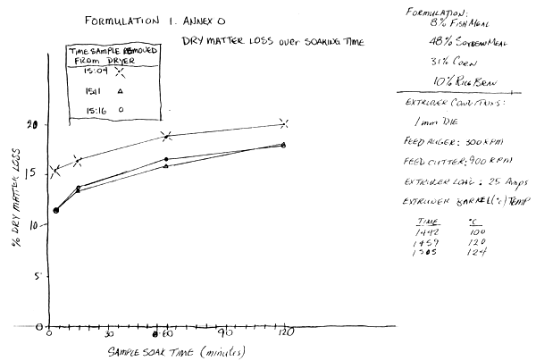
First Formulation (Feed 1, Annex N) 30/9/91
Grinding—
Grinding was generally good, but sieving was poor. One mm particles were mixed in with the flour. These particles were visible in the finished pellets.
Conditioning—
No water was added in the mixer. Steam and water are added in the conditioner, and steam is injected into the extruder barrel.
Extruder Conditions—
Die: 1 mm with 3 out of 6 bores plugged with coins to increase internal pressure.
Feed Auger: 300 rpm
Feed Cutter: 900 rpm
Extruder Voltage: 400 V
Extruder Current Load: 25 Amps
Temperature of the Extruder Barrel:
| Time | °C |
| 1442 | 100 |
| 1459 | 120 |
| 1505 | 124 |
Output not measured, but takes about 1 hour to extrude 100 kg of this feed.
Dryer Conditions:
Dryer Voltage: 400 V
Dryer Current Load when heating: 60 Amps
Comments: They say this is the best feed that has been made so far with the extruder.
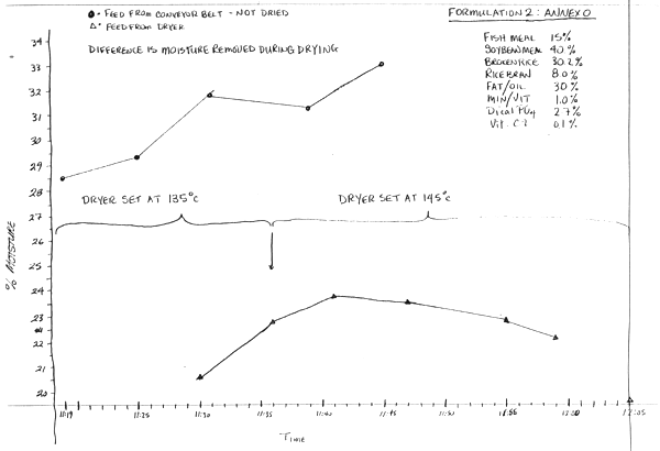
Second Formulation (Feed 2, Annex N) 9/10/91
Extruder Conditions-
Die: 1 mm with 3 out of 6 bores plugged with coins to increase internal pressure.
Feed Auger: 350 rpm
Feed Cutter: 1100 rpm
Extruder Voltage: 400 V
Extruder Current Load: 17.25 Amps
Steam Pressure: 60 psi
Temperature of the Extruder Barrel:
| Time | °C | |
| 11:15 | 80 | Started to feed extruder |
| 11:17 | 96 | Feed from die |
| 11:21 | 116 | |
| 11:25 | 120 | |
| 11: | 120 | Extruder shut off |
Output not measured, but takes about 1 hour to extrude 100 kg of this feed.
Dryer Conditions:
Dryer Voltage: 400 V
Dryer Current Load when heating: 60 Amps
Dryer Temperature set at 135°C at 11:15, INCREASED TO 145°C at 11:36.
| Time | °C |
| 11:15 | 119 |
| 11:41 | 125 |
| 11:51 | 135 |
| 11:59 | 136 |
REGIONAL SEAFARMING DEVELOPMENT AND DEMONSTRATION PROJECT
RAS/90/002
 |
Mailing Address : c/o UNDP | Office | : Network of Aquaculture Centres in Asia |  |
|
| G.P.O. Box 618 | Address | : National Inland Fisheries Institute | |||
| Bangkok 10200, Thailand | Kasetsart University Cameus | ||||
| Cable Address: | UNDEVPRO BANGKOK | Bangkhen, Bangkok 10900, Thailand | |||
| Telex: | 84267 NACA TH., 82392 ESCAP TH. | Telephone | : 561.1723, 851.1729 | ||
| Facsimile | : (662) 851.1727 | ||||
| FACSIMILE TRANSMISSION | |||||
| Date: 11/22/91 | Series No.: 1991/ | ||||
TO: Dr. Pigott or Student if he is unavailable IFST, UW, Seattle, WA. USA. (206) 685–3275
From: Thom Wilson, NIFI, Bangkok, Thailand.
Total No. of Pages Including this transmittal sheet: 4
MESSAGE
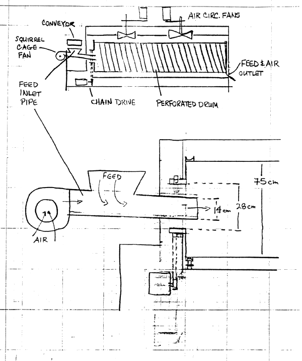
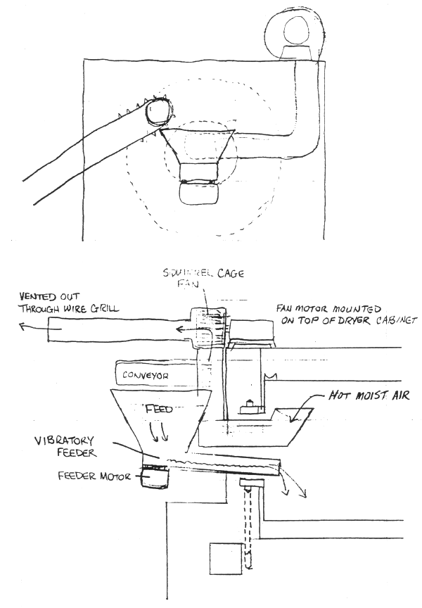
Dr. Pigott : Here at NIFI we have a feed dryer installed which was very poorly designed, and we are instigating some modifications. We had an engineer from the manufacturer visit yesterday, and he wasn't very happy when he left. He seemed surprised that we had so many suggestions on how he could improve the design! Basically what we have is a rotating perforated drum 3.3 m long inside a large box which has electric coil elements mounted on the sides. Two fans mounted in the roof of the box blow the air around inside the box, but it is not likely that much air gets through the holes as they are 2 mm diameter with 2 mm between holes. There is a spiral screw inside the drum 14 cm deep with 14 cm between turns. The drum is about 75 cm in diameter. Feed is transported to the dryer by a lugged conveyor belt and then drops into a 14 cm pipe, where it is blown into the drier using unheated air from a 18 cm squirrel cage fan. Feed from the conveyor has about 30% moisture, and has a temp of about 120°C when it exits the extruder. It travels on the conveyor about 2 m before entering the dryer. The dryer can be set to a maximum temp of 149°C. If we feed the extruder using a screw speed of 300 rpm, feed exits the dryer uniformly dry but about 19% moisture (Dryer T = 145°C). If we feed at 400 rpm the feed exits the dryer not uniformly dry. Wetter feed is mixed in with drier feed. Feed exits the drum through a 40 cm × 20 cm opening, when the opening is at the 6 o'clock position.
The problems as I see them are : there is no counter-current air flow; feed is being blown in using unheated air which cools down the feed before it enters the dryer. There is a lot of moisture being trapped inside the drum and it cannot escape without sufficient air flow. Air escapes where the feed comes out. This vent is low, which means the hottest moistest air will not be able to get out. The feed is being channelized and falling over itself between the turns of the spiral-ie-clumped at the bottom of the drum-not evenly spread out so air moves non-uniformly through the feed mass, and drier feed is ramixed with wetter feed at higher extruder output. Unfortunately the dryer cannot be replaced with something that works, so we have to modify what we have. The engineer said he thought putting in a vibratory feeder was a good idea, but said it would be difficults to induce counter current air flow. He suggested ducting the fan in such a way that hot air would takes from the box and blown into the drum. The problem is that there isn't enough dry air at ambient temperatures being sucked through the drum. And if we can blow hot air into the drum, then we can suck it out. The main restriction is that we have a 28 cm collar at the head of the drum. I believe it is possible to put a vibratory feeder with a relatively small cross section, say 16 cm × 8 cm, underneath the 14 cm pipe if the pipe is raised 4 or 5 cm. A larger capacity fan can be mounted on top of the cabinet and the pipe ducted in a way that avoids the hopper below the end of the conveyor. The fan can be vented to the outside of the building through a wire grill. If the end of the pipe is angled up inside the drum and angle cut, it should not suck feed from the lower part of the drum or from the feeder. Drawing air from the drum will cause a negative pressure in the drum which will encourage hot air to pass through into the perforated metal drum from the cabinet. Ambient temp air will be drawn in through the far end of the dryer, either through the port where feed exits the drum, or around the end of the drum into the cabinet where it will be heated.
Our Fax Number: (662) 561 1727
I wonder if you have any comments or suggestions? They would be appreciated. Also if you could fax me some info comparing drying with and without counter current airflow, and something about air volumes and drying efficiency, so we can get a better idea how much bigger the fan should be, Anything else you can think of which might be applicable would be appreciated as well.
Regards.
Thom Wilson
Institute for Food Science and Technology
| College of Ocean and Fishery Sciences | Phone: 206-543-4281 |
| University of Washington, HF-10 | 206-685-2033 |
| Seattle, WA 98195 | FAX: 206-543-1417 |
| December 23, 1991 | |
| Mr. Thom Wilson | |
| FAX No. 011-66-2-661-1727 |
Dear Thom:
Sorry, I have been out of town for several days and am late in answering your FAX. You have answered your own questions in your letter. This is certainly a non-functional design of a dryer. The main problem is certainly that there is insufficient air flow and poor contact between air and feed. There is no way that the present air volume throughput can efficiently dry the feed to your specifications.
Assuming that you have to use this dryer and can not replace it, I suggest that you see if flutes can be put on the drum to make the meal tumble for better air/feed contact. The air should be heated prior to going into the dryer and it should be introduced countercurrent into the drum so that it contacts the feed as it tumbles off of the flutes to the bottom of the drum.
Not knowing the mass/energy balances, it is not possible to specify new operating conditions. However, judging from the results of the present setup, I predict that the above changes would do the job without any other additions. That is, put the existing fans at the inlet or outlet of a box, put the coils in the box, and direct the air (by duct) from the box to the inside of dryer drum. The perforated drum is rather worthless if the air is not within the dryer. This should be a rather simple change if I read your letter and drawing correctly. Better send the “engineer” to take our Fd Engr course!
| GMP/mg |  |
FROM: Hastings, W., and D. Higgs. 1980. Fish Feed Technology.
ADCP/REP/80/11. FAO, Rome.
Table 1
Water Stability of Test Pellets made from a Standard Formula as Measured by the Percentage of Solids Retained on a Screen after Ten Minutes in Quiet Water
| Treatment | Percent Retained |
| 5% gelatinized corn solids (dry) | 85.0 |
| 5% bentonite | 88.6 |
| Control formula - unground | 90.0 |
| 5% guar meal | 90.2 |
| 5% gelatinized corn solids - wet | 92.0 |
| Control formula ground through 2 mm screen | 93.0 |
| 5% rice mill dust, 75 microns diameter | 93.0 |
| 5% soybean flour | 94.0 |
| 5% lignin sulfonate | 94.0 |
| 5% rice mill dust sifted through 180 microns | 96.2 |
| 10% rice mill dust sifted through 180 microns | 98.2 |
| 20% rice mill dust sifted through 180 microns | 98.5 |
Pellets of 3 mm diameter were readily accepted by fish weighing from 5 to 1 500 grams, all fish ingesting pellets of 3 to 9 mm length. Fish weighing more than 225 grams accepted pellets of 5 mm diameter × 5 mm length, and fish 454 grams and over accepted 6 mm diameter × 6 mm length pellets. Hard pellets of 13 mm diameter × 13 mm length were not readily accepted by any test fish.
Ten minutes after feeding in water at temperatures of 25 to 35°C, from five to nine percent of total fish weight was wet stomach contents. This was equivalent to one to three percent fish weight as dry pellets. In the process of ingesting pellets, fish consumed water so that stomach contents were found to be 70 to 80 percent moisture. One hour after feeding, about 75 percent of the total gastro-intestinal contents remained in the stomach, considerable amounts of protein and fat were gone from the food mass in the intestines, the water content in the stomach had increased, and the fish abdominal cavity was still greatly distended.
4.7 Hazards of Feeding Hard Pellets
For some fish there is a danger of over-feeding with hard pellets, causing swelling and rupture of the stomach. Over-feeding also mechanically forces pellets past the point of gastric activity, resulting in inefficient digestion. Another hazard with use of hard pellets may occur during winter feeding when fish ingest a full stomach capacity on a warm day followed by a period of cold weather. This may result in fermentation of undigested feed in the stomach with gas formation. Fish may float upside down, exposed to extremes in air temperatures and predation.
4.8 Pellet Hardness and Stability
Ideal pellets lure fish by their size, shape, and organoleptic properties and are available in water without loss of components. This last factor, called “pellet quality” is important for good feed conversion. A measure of pellet quality as applied to dry feeding conditions is the amount of small broken pieces of fines created during handling. this may be related to the abrasive pressure required to break them down. However, dry pellet quality expressed as hardness or in the percentage of fines does not necessarily correlate with water stability. The average high-quality feed pellet made for poultry, swine, and beef, high in cereal grains, becomes mushy within minutes after immersion in water. There is evidence that coarse-textured feeds, water soluble, and hygroscopic ingredients weaken pellet structure in water, allowing components to separate and making the feed only partially accepted.
A laboratory technique for measuring pellet stability in water is useful for establishing feed formulation and processing specifications. One such test which has given reproducible values and shown good correlation with pellet recovery from feeding platforms and bottom sampling devices, is as follows:
10 grams of pellets of equal diameter and length are distributed uniformly on a screen tray approximately 100 cm2 in an area with raised sides. Mesh openings are slightly less than pellet diameter.
Duplicate samples are lowered into quiet water of an aquarium or tank. If clumping or floating occurs, a piece of cut screen is placed on top of the pellets to hold them under water in a scattered position.
After 10 minutes the trays are removed from water, slanted to drain, and placed in a moisture oven at 130°C for 2 hours, then cooled in a dessicator.
The residue on the screen is recorded as dry solids not lost in water. Total solids in 10 grams of air-dry pellets are determined by oven-dry duplicate samples. Nutrients lost by leaching in water may be measured at this point by freeze-drying the residue on trays and comparing the chemical analysis with untreated pellets.
The ratio of dry solids on the screen after 10 minutes in water to total dry solids in air-dry pellets, is used as a comparative measure of pellet water stability.
During the early days of using hard pellets for fish culture, a random selection of commercial feed was examined for water stability by this technique and none was found to have more than 60 percent retention after 10 minutes in water. To obtain more stable fish feed pellets and thereby improve feed conversion, guidelines for the industry have been proposed as follows:
Before pelleting, grind the mixed feed through a 2 mm screen to an effective size of 125 microns.
Replace at least 5 percent of a non-essential ingredient with an organic flour such as rice dust, dried wood pulp liquor, wheat endosperm, or other binder.1
Operate the pellet mill at its optimum rated amperage for maximum compression and extrusion pressures.
Add sufficient dry steam to condition the soft feed to a temperature of 85–90°C, thus causing gelatinization of raw starch on the surface of all starch-containing ingredients.
Cool and dry pellets before conveying to storage or bag-off bins.
Table 1 shows the formula of a standard feed used in testing water stability of pellets. It is typical of commercial catfish rations used in the southern part of the United States. Basically it complies with the requirements of a 30 percent protein feed, 25 percent of which is of animal source, with a protein to calorie ratio of 90 (grams protein in 100 grams feed × 100 divided by kcal/100 grams feed).
Table 2
Physical Measurements of Pellet Stability of a Standard Catfish Feed
| Process variable | Water stability % retained 10 minutes in running water | Broken by Stokes pellet hardness tester |
| Unground, no steam, thin die | 21.5 | zero pressure |
| Unground, no steam, thick die | 24.3 | zero pressure |
| Unground, added steam, thin die | 31.3 | 1 kg |
| Unground, added steam, thick die | 78.9 | 3 kg |
| Ground, no steam, thin die | 65.8 | 3 kg |
| Ground, no steam, thick die | 74.5 | 4 kg |
| Ground, added steam, thin die | 84.9 | 8 kg |
| Ground, added steam, thick die | 88.0 | 13 kg |
| Ground plus 20% gelatinized potato starch and 6% added water, no steam | 98.9 | 20 kg |
Note: Water movement through the test container may be used as an alternative to use of quiet water.
Table 2 shows the water stability of ground and unground standard feed (see Table 1) and the effects of replacing 5 percent of rice bran with various organic and mineral materials suggested as binders. Formulae for common and mirror carp are similar to those for catfish with the exception that ground wheat will replace rice bran or wheat offal. High-wheat feeds are very water-stable if properly steam conditioned before compression and extrusion in a pellet mill.
Feeds low in starch require a thick ring die and extra steam for conditioning. Special binders of starch origin provide some degree of water stability for pellets made with lowstarch formulae.
4.9 Floating Pellets
Fish feeds may be pelleted by what is sometimes called the “extrusion” process, thereby expanding rather than compressing the various ingredients. Variations in formulation and processing allow a wide range in bulk density; 0.25 to 0.3 g/cc being common for fish feeding. This feature makes them attractive for certain types of fish culture. Fish may be observed while eating and the amount of feed limited to that which is accepted. The number of fish in a water impoundment and their health can be observed without sampling.
In general, the processing of expansion of extrusion consists of:
conditioning soft feed which is in meal form to contain 25–30 percent water,
conveying this conditioned feed by auger into a pressure-sealed cylinder,
injecting steam, thus decreasing friction of material within the cylinder and increasing gelatinization of raw starch.
extruding to atmospheric pressure, almost exploding the material through holes in the die plate at the end of the cylinder.
cutting off the extruding ribbon at the outside of the die plate by a rotating knife, and
drying the pellets in a high-temperature oven at about 120°C to a moisture content suitable for storage.
Several details should be added to this general process description for a better understanding of floating pellets. The feed formula is important in obtaining a desired expanding texture. Cereal grains can be expanded to a very low bulk density, whereas protein concentrates low in starch may remain unaltered in bulk density. Raw starch is a requirement of a good floating pellet; 90 percent being gelatinized during the 30 to 60 seconds the feed is in the expander cylinder. Pressure builds up to several atmospheres due to forward passage of the material into a smaller volume. Superimposed steam causes a high product temperature, changing the consistency of the material from a free-flowing meal to a dough. By the sudden release of pressure at the discharge end, the feed assumes a “puffed rice” texture like some breakfast foods and snacks.
Following oven drying, a standard pellet cooler is often used to lower product temperature after internal moisture is less than 13 percent. Even with this treatment, previous high temperature partially destroy heat-labile vitamins and decrease the availability of some amino acids. Rather than over-fortifying the formula before pelleting, as is done for preparation of hard pellets, heat-sensitive additives may be sprayed onto expanded pellets after extrusion.
Biological tests under pond conditions with natural food available have shown no difference in growth of catfish and goldfish using a formula feed processed by hard pelleting and by the extrusion process. Also no significant difference was found chemically in total crude protein or in individual amino acids for several formula feeds each prepared as hard pellets and as extruded pellets. However, testing fish growth in tanks and cages has revealed a partial destruction of some nutrients in extruded feeds.
There is evidence that fish fed with floating pellets contain more liver and body fat than those fed the same formula feed processed as a hard pellet. This may be due to the increased digestibility of the carbohydrate part of the ration. The expansion process is expensive compared with other methods of feed manufacture in terms of equipment cost, heat used in generating steam and in oven-drying, and in loss of nutrients. It may be concluded that the value of extruded pellets is best measured by practical feeding tests using data on feed conversion, cost of management, and acceptability by fish as deciding factors.
PROTEIN SOLUBILITY AS AN INDICATOR OF OPTIMUM PROCESSING OF SOYBEAN MEAL
N. M. Dale, M. Araba and E. Whittle
Extension Poultry Science Department
University of Georgia
Athens, Georgia 30602
Soybean meal is the principal protein source for poultry and swine diets in much of the world. This ingredient is, however, a by-product and must be processed prior to use in poultry feeds. Following the solvent extraction process, soybean meal is heated to recover hexane and also to destroy anti-nutritional factors. Raw soybeans contain a variety of toxic factors, including trypsin inhibitors (Kunitz, 1945; Bowman, 1946; Lipke et al., 1954; Yamamoto and lkenaka, 1967; Frattali and Steiner, 1968), hemagglutinins (Liener, 1953), saponins (Gestetner et al., 1966) and antivitamin A (Summer and Dounce, 1939). Fortunately, the toxic factors in raw soybeans are heat labile and are destroyed by adequate processing.
Either underheating or overheating (i.e. underprocessing or overprocessing) of soybean meal is deleterious to the nutritional value of this ingredient. Unless the meal has been adequately heated, high levels of the various anti-nutritional factors remain in the meal. These factors, of which the trypsin inhibitors are the most widely known, depress animal performance. Overheating soybean meal is similarly deleterious to performance, presumably due to reduced lysine availability. Mauron (1981) reviewed the chemical reactions of the maillard or browning reaction, where the epsilon amino group of lysine becomes irreversibly bound to carbonyl Rroups provided by reducing sugars.
In vitro tests to determine adequacy of soybean processing are of great interest to quality control laboratories. To detect underprocessing, trypsin inhibitor activity tests have been developed by hestfall and Hauge (1948), Kakade et al. (1969) and Hammerstrand et al. (1981). Dye-binding assays, such as that of Moran et al. (1963), have been proposed as means of detecting overprocessing of soybean meal. Unfortunately, neither the trypsin inhibitor activity assays nor the dye-binding tests are commonly used by quality control laboratories, presumably due to the time and expense required by these procedures. By contrast, the urease activity test has been widely used, and at this time is the test most frequently employed to determine the quality of soybean meal processing. Caskey and Knapp (1944) reported that the destruction of the urease enzyme by heat treatment of soybeans was closely related to the improvement in nutritive value of the meal. It is presumed that heat treatment destroys the urease enzyme in a manner proportional to the destruction of trypsin inhibitor and other toxic factors. While criticisms have been raised concerning the reliability of this assay (Borchers et al., 1947; De Schrijver, 1977) it has remained the most popular test of soybean processing.
Balloun et al. (1953) reported that while urease activity is a satisfactory measure of heat treatment of soybean meal up to the point of optimum heating, it is of no value in detecting possible overprocessing. Urease activity is measured by pH change; thus, there is no negative scale associated with the assay. Once the heating of soybean meal reaches a point where urease activity (i.e. pH change) is 0.00, the test is insensitive to further heating of the meal. Numerous researchers, including McNaughton et al. (1980) and Dale et al. (1986) have shown that meals with 0.00 urease activity do not necessarily have impaired nutritive value. Thus, the use of the urease test as a measure of overprocessing of soybean meal is not justified. It would appear that the urease test is used for this purpose simply on pragmatic grounds. As the asay gives useful information regarding underprocessing of soybean meal, it has been employed to detect overprocessing in order to avoid conducting a second assay on each sample of soybean meal.
An alternative means of evaluating the processing of the soybean meal was developed by Rinehart. This assay (see appendix), which uses protein solubility in 0.2% potassium hydroxide solution as an indicator of soybean processing, was never published in the scientific literature. It has been used in quality control programs by several major feed companies in North America and is widely used by the Brazilian poultry industry. Protein solubility in potassium hydroxide is virtually 100% in raw soybean meal. With increased heat treatment solubility decreases rapidly. According to Brazilian sources (M. Mendes, A. Tardin, personal communication) samples of soybean meal with solubilities in excess of 85% are considered to be underprocessed, and those with solubilities of less than 75% are overprocessed. Any evaluation of the assay, in which laboratory data is compared with chick response, has apparently not appeared in the scientific literature. A series of tests were conducted with both underprocessed and overprocessed soybean meal to evaluate the protein solubility assay as a possible replacement for urease activity in quality control programs.
Overprocessed Meal:
To evaluate the applicability of the protein solubility assay analytical values were compared to the results of in vive trials. In each assay, a quantity of commercially produced soybean meal was obtained from a local feed mill. It was subdivided into 25 pound lots, each of which were cooked for varying lengths of time in an autoclave. The autoclave was a useful means of simulating overprocessing conditions, making it possible to precisely regulate the heating time for each sample. Meals cooked for varying periods were evaluated for urease activity and protein solubility, and then incorporated into practical chick diets in 21-day growth assays. As noted in Table 1, the basal diet in which the various meals were incorporated was formulated to be limiting in protein and especially in lysine. Thus, any difference in lysine availability would be detected by differing chick performance.
Table 1. Composition and calculated analysis of basal diet (Expts. 1–4)
| Ingredients | Basal Diet (%) |
| Yellow corn, ground | 72.48 |
| Soybean oil meal1 | 20.00 |
| Corn gluten meal | 3.00 |
| Defluorinated phosphate | 1.96 |
| Poultry fat | 1.00 |
| Limestone | 0.72 |
| Sodium Chloride | 0.30 |
| Vitamin mix2 | 0.25 |
| Mineral mix3 | 0.05 |
| DL-methionine | 0.09 |
| Calculated Analysis | |
| Metabolizable energy, kcal/kg | 3190 |
| Crude protein, % | 17.5 |
| Lysine, % | 0.81 |
| Methionine, % | 0.40 |
| Methionine + Cystine, % | 0.69 |
1 Subjected to different autoclaving time at 15 psi.
3 Trace mineral mix provides (ppm of diet): Mn, 60; Zn, 50; Fe, 30; Cu, 5; I, 1.5.
In Experiment 1, subsamples of a quantity of soybean meal were autoclaved for 0, 5, 10, 20, 40 and 80 minutes at 15 lb/sq. inch. Urease activity was 0.000 after 10 minutes of heating, and was thus unable to reflect the effect of further processing (Table 2). By contrast, protein solubility values decreased with each increase in heating time and did not approach 0.00 even at 80 minutes. Decreases in chick growth with increased processing time were much more closely related in protein solubility thn to urease values. In this experiment, a significant growth depression was noted when soybean meal was mprocessed for 20 minutes or longer. This data would suggest that when protein solubility drops below 74%, nutritive value begins to be impaired.
Table 2. Relationship between urease activity, protein solubility, and chick performance (Expt. 1)
| Treatment (minutes) | Urease Activity1 | Protein Solubility (%) | Weight Gain2 | Feed/ Gain |
| 0 | 0.03 | 86.0 | 450a | 1.79a |
| 5 | 0.02 | 76.3 | 445a | 1.67ab |
| 10 | 0.00 | 74.0 | 424a | 1.83ab |
| 20 | 0.00 | 65.4 | 393b | 1.89b |
| 40 | 0.00 | 48.1 | 316c | 2.04b |
| 80 | 0.00 | 40.8 | 219d | 2.55c |
abcd
(P ≤ .05)
1 pH change
2 Grams/chick, 0–21 days
In a second study, meal was autoclaved for 0, 5, 10, 20 and 40 minutes. As the meal had a urease activity of 0.00 prior to autoclaving, the urease test was not able to reflect any of the additional processing. Protein solubilities again decreased with each increase in heating time, dropping from 82.3% to 46.1% at 40 minutes (Table 3). In this study, chick performance appeared to be impaired when the protein solubility of soybean meal dropped below 67%.
Table 3. Relationship between in vitro tests and performance of chicks fed heated soybean meal (Expt. 2)
| Treatment (minutes) | Urease Activity1 | Protein Solubility (%) | Weight Gain2 | Feed/ Gain |
| 0 | 0.00 | 82.3 | 423ab | 2.26a |
| 5 | 0.00 | 72.6 | 452a | 2.12a |
| 10 | 0.00 | 66.9 | 444a | 2.24a |
| 20 | 0.00 | 60.5 | 405c | 2.36a |
| 40 | 0.00 | 46.1 | 254d | 2.60b |
abcd(P ≤ .05)
1 pH change
2 Grams/chick, 0–21 days
Underprocessed Soybean Meal
A quantity of solvent extracted raw soybean meal was obtained from a major soybean processor. In one experiment, subsamples of the meal were autoclaved for 0, 15, 30 and 60 minutes. These samples were tested for urease activity and protein solubility, and were incorporated into the basal diet described in Table 1. The urease value of 2.4 noted for the and PUSKI, G. 1974. Problems encountered in measuring trypsin Inhibitor activity of soy flour: Reports of a collaborative analysis. Cereal Sci, Today. 19:513–516.
SMITH. C., MEGEN, W.V., TWAALFHOVEN, L., and HITCHCOCK. C. 1980. The determination of trypsin inhibitor levels in foodstuffs. J. Sci. Food Agric. 31:341–350.
VISWANATHA. T., and LIENER, L. E. 1954. Inhibition of trypsin: I. Sequence of mixing the reactants. J. Biol. Chem. 210: 97–108.
[Received August 25, 1988. Revision received March 12, 1989. Accepted May 8, 1989.]
Effect of Hybrid and Physical Damage on Mold Development
and Carbon Dioxide Production During Storage of High-Moisture Shelled Corn1
D. FRIDAY,2 J. TUITE,3 and R. STROSHINE4
| ABSTRACT | Cereal Chem. 66(5): 422–426 |
Carbon dioxide (CO2) evolution was measured during storage of shelled corn at 26°C and 20.5% mc. The effects of hybrid and physical damage on mold development were determined. Hybrids were selected as either susceptible or resistant to storage mold on the basis of laboratory tests. Number of propagules, percent seeds infected, visible mold, and percent mold damage were the criteria used to evaluate mold growth. Results of the CO2 evolution tests showed significant differences in storability due to hybrid. CO2 production and associated measures of mold growth for hybrids FRB73 × Mo17 and FR35 × FR20 were significantly lower than for hybrids DF20 × DF12 and Pioneer 3377. For all hybrids except DF20 × DF12, CO2 was produced at a slower rate than that predicted by Saul's curves. The corn dropped in grade to U.S. no. 4 at 0.5% dry matter loss.
Carbon dioxide production is used extensively to estimate corn deterioration (Saul and Lind 1958, Saul and Steele 1966, Fawole 1969, Seitz et al 1982). Allowable storage time of shelled corn is based on dry matter loss (DML) as predicted by an equation (Steele et al 1969) and is a function of temperature, moisture, and mechanical damage. Steele et al (1969) proposed 0.5% DML as an index of deterioration of shelled corn because they believed that exceeding it could cause a loss of grade. Significant hybrid differences in resistance to storage mold have been demonstrated (Moreno and Christensen 1971, Cantone, et al 1983, Tuite et al 1985). Although invasion by fungi is affected by the amount and kind of damage, differences among corn genotypes persist (Tuite et al 1985). Yao (1987) detected differences among corn genotypes in resistance to three species of Penicillium as measured by visible mold and number of propagules. He inoculated kernels killed by heat at 105 spores/g. Tuite and Stroshine (unpublished) found that hybrid FRB73 × Mo17 was consistently resistant to Penicillium spp. over three crop years, suggesting that resistance is stable for certain hybrids. The nature of these differences in resistance has not been identified.
Thompson (1972) developed a simulation model to predict changes in moisture, temperature, and grain condition during high-moisture corn drying that used CO2 production as a measure of deterioration. He used the equation of Steele et al (1969) to calculate the amount of CO2 produced at the “standard” conditions of 15.5°C (59.9°F), 25% mc, and 30% mechanical damage:
Y = 1.3 [exp (0.006t) - 1] + 0.015t (1)
where Y = grams of CO2 produced per kilogram of dry matter and t = time in hours. The time required to produce a given amount of CO2 under conditions other than the standard was predicted from the expression (Steele et al 1969):
T = Tt × Mt × Mm × Md (2)
where T = estimated time in hours to produce a given amount of CO2; Tt = time to produce the CO2 at 15.5°C, 25% mc, and 30% mechanical damage; and Mm, Mm, and Md = multipliers for temperature, moisture, and damage calculated from equations reported by Steele et al (1969) and Thompson (1972).
Thompson's model and the criterion of 0.5% DML have been used extensively in low-temperature grain drying to predict corn deterioration and allowable storage time. To date, investigators have assumed no differences in allowable storage time due to hybrid. However, hybrid differences in susceptibility to storage mold suggest that hybrid has a significant effect on CO2 production, and this effect should be quantified.
Our objectives were: 1) to determine CO2 production of several hybrids previously determined to differ in susceptibility to storage mold, 2) to compare CO2 production with other measures of deterioration, and 3) to compare these measurements with Saul and Steele's prediction of allowable storage time. A more detailed description of the study is given by Friday (1987).
1 Journal Paper 11.517 of the Purdue Agricultural Experiment Station.
2 Agricultural engineer. Weaver Popcorn Company, Van Buren, IN 46991.
3 Professor, Department of Botany and Plant Pathology, Purdue University, West Lafayette, IN 47907.
Reference to a company or trade name does not imply approval or recommendation of a product by Purdue University.
• 1989 American Association of Careal Chemists, Inc.
MATERIALS AND METHODS
Carbon dioxide production during storage of mold resistant and mold susceptible hybrids was measured by an absorption technique similar to that used by Steele and Saul (1968) and Fernandez et al (1985). The system consisted of the following steps: CO2 removal, humidification, sample storage and aeration, water absorption, and CO2 absorption. Each experiment included six separate CO2 absorption systems that allowed three replicates of two treatments. The experiment was conducted in a temperature controlled room at 26°C. Ammonium phosphate was used to maintain corn at 20.5% mc (91.0% rh at 25°C).
Airflow rates were monitored using Matheson acrylic purge
| Sample | sample # | TIU/mg sample |
| Ground whole soybeans | 1 | 126.1 |
| 2 | 136.7 | |
| 3 | 103.1 | |
| Steamed Full-fat Soybean Meal | 1 | 96.0 |
| (Commercial) | 2 | 99.8 |
| Mech. Extracted SBM | 1 | 29.1 |
| (Commercial) | 2 | 27.8 |
| Boiled Extracted SBM | 1 | 4.3 |
| 2 | 4.7 | |
| 3 | 4.3 | |
| Acid-treated Extracted SBM | 1 | 5.7 |
| 2 | 6.3 | |
| 3 | 4.5 | |
| Base-treated Extracted SBM | 1 | 7.2 |
| 2 | 6.9 | |
| 3 | 5.3 | |
| Soybean Meal Feed | 1 | 15.8 |
| approx. 50% | 2 | 15.6 |
| mech. extracted SBM | 3 | 14.7 |
Semi-purified Test Diet for Warmwater Fish (WWTD)*
| Ingredient | Percentage of Diet |
| Casein | 32.0 |
| Gelatin | 8.0 |
| Dextrin | 30.0 |
| Cellulose Flour | 19.0 |
| Fish Oil | 3.0 |
| Soybean Oil | 3.0 |
| Mineral Mixture | 4.0 |
| Vitamin Mixture | 1.0 |
Feeds used in First Digestibility Trial
Feed 1—
99% WWTD
1% chromic oxide.
Feed 2—
49% WWTD
50% mechanically extracted soybean meal
1% chromic oxide.
Feed 3—
49% WWTD
50% extracted soybean meal which had been boiled for 60 minutes.
1% chromic oxide.
Feed 4—
49% WWTD
50% extracted soybean meal which had been treated with an acid solution.
1% chromic oxide.
Feed 5—
49% WWTD
50% extracted soybean meal which had been treated with a basic solution.
1% chromic oxide.
Feeds used in Second Digestibility Trial
All feeds contained 1 % chromic oxide.
| Feed | 1 | 2 | 3 | 4 | 5 | 6 |
| Broken Rice | 30.0% | 37.5% | 45.0% | 52.5% | 60.0% | |
| WW Test Diet* | 91.0% | 61.0% | 53.5% | 46.0% | 38.5% | 31.0% |
| Min/Vit/Cr203 | 9.0% | 9.0% | 9.0% | 9.0% | 9.0% | 9.0% |
* Formula as above minus minerals, vitamins.
REFERENCE
Stevenson, Audrey E., and H. De Langen. 1960. Measurement of Feed Intake by Grazing Cattle and Sheep. VII. Modified Wet Digestion Method for Determination of Chromic Oxide in Faeces. N.Z.J. agric. Res. 3: 314-319.
MATERIALS
Equipment
Muffle Furnace — [at 600°C]
Ashless Filter Paper [Whatman No. 40]
Weigh Balance — [accurate to 4 significant places]
125 mL Erlenmeyer flasks accurately calibrated to 100 mL
Large test tubes calibrated to 25 mL.
Reagents and Chemicals
Acid Mixture
250 mL concentrated H2SO4; 250 ML H3PO4
500 mL de-ionized water, 50 mL 10% solution of MnSO4 • 4 H2O
Dilute Bromate (KBrO3) Solution
50 mL 4.5% KBrO3; 450 mL de-ionized water
10% NaOH
Fish Meal ashed at 550°C to be used in K2CrO4 digestions
K2CrO4 Standard Solution [1 mL = 1 mg Cr2O3]
2.555 g K2CrO4 is dissolved in 1 L de-ionized water.
PROCEDURE
Ash samples of diets (approx. 100 mg) or feces ( 50 mg) overnight at 550°C. in borosilicate scintillation vials.
Transfer ash to 125 mL Erlenmeyer flasks with 6 mL of acid mixture.
Put flasks on hot plate, and bring to boil, then add 3 mL of 4.5% KBrO3.
Boil until deep purple color is evident and for 0.5 to 1 MIN. after white smoke (SO3 fumes) appears. Remove from heat and cool.
Add 20 mL of dilute KBrO3.
Boil for 3 - 4 MIN., cool, then dilute up to 100 mL.
Transfer 10 mL of the solution to a calibrated 25 mL test tube.
Add 5 mL 10% NaOH, and heat in boiling water bath for 5-10 MIN.
Cool and slowly fill to 25 mL mark with NaOH to avoid breaking floculate
If necessary, cap tube and invert gently to mix.
Filter through No. 40 Whatman filter paper.
Measure absorbance at 400 nm in spectrophotometer.
Preparation of Standard Curve
Add approximately 100 mg of fish meal ash to each flask to be used in chromium determination for the standard curve.
Add .25 mL, 0.5 mL, 1.0 mL, 1.5 mL, 2.0 mL, and 2.5 mL of the chromate standard solution to each of the flasks, and prepare according to the method. [These aliquots provide a standard curve which is suitable for estimating chromium content of samples using the weights of diets and feces suggested.] Measure absorbance at 400 nm.
Determine standard curve by plotting on graph paper or obtain regression equation and use equation to estimate mg dye absorbed/gram of meal.
MEASUREMENT OF FEED INTAKE BY GRAZING CATTLE AND SHEEP
VII. MODIFIED WET DIGESTION METHOD FOR DETERMINATION OF CHROMIC OXIDE IN FAECES
By Audrey E. Stevenson and H.de Langen, Ruakura Animal Research Station, Department of Agriculture, Hamilton
(Received for publication, 17 December 1959)
Summary
A wet digestion colorimetric method for the determination of chromic oxide marker in faeces is described.
In comparison with other methods examined it has the following advantages:
Less critical conditions.
Higher reproducibility.
Higher recovery.
Higher daily output.
Introduction
Increasing use of chromic oxide as a faeces reference substance in herbage intake measurement has made it necessary to investigate a more rapid and reliable routine procedure for estimating chromic oxide than the wet digestion method of Christian and Coup (1954), reported in Part VI of this series.
Methods of several different authors have been examined and assessed as a routine analysis on accuracy, speed, and lack of critical conditions.
A rapid and accurate wet digestion colorimetric method is presented in this paper.
DISCUSSION OF METHODS
Fusion Methods
The alkaline-oxidation fusion methods of Barnicoat (1945). Kane et al. (1950), Schurch et al. (1950), Raymond and Minson (1955) and Kameoka et al. (1957) were examined.
In fusing with sodium peroxide the loss in weight of the nickeil crucible (25 ml) was found to be 2-5 mg per assay. The crucible became pitted and eventually holed in the base and the retention of chromate in the nickel oxide precipitate was appreciable. Both these disadvantages increased with rise in temperature. Temperature deviations of = 10°C in the muffle furnace produced differences in results of 5% and more. Fusing over gas burners at low temperature (Kameoka et al. 1957) resulted in loss of chromate up to 20% after two minutes melting. At no time was it found that the loss of chromate in the nickel oxide precipitate was a standard one of 2% as described by Barnicoat (1945).
N.Z.J. agric. Res. 3: 314-319
The methods of Kane et al. (1950), and Raymond and Minson (1955) developed from that of Edin et al. (1945), showed less loss in weight of the nickeil crucible. In fusing with a mixture of sodium and potassium hydroxides, together with their carbonates and nitrates in 1 : 2 molecular ratio (Kane et al. 1950) the mixture tended to foam and creep over the edge of the crucible and the blank readings were high and variable, giving low results and poor reproducibility. Changing the carbonate : nitrate ratio to 10 : 1 (Sandell 1950) lowered the blank reading, but foaming over still occured and was found to be due to the nitrates.
Maunsell (1944 stated that fusion with sodium carbonate alone does not bring all the chromic oxide into solution and that a small amount of an oxidising substance must be added to the fusion mixture to convert all the chromium to chromate. It has been found, however, that fusion with sodium carbonate with air oxidation converts all the Cr2O3 to the soluble chromite, and partially further to chromate. Hydrogen peroxide readily completes the oxidation. Thus the large expenditure of nickel crucibles and the retention of chromate in the nickel oxide precipitate, can be avoided if the oxidising substance is added to the crucible after fusing.
The ashed sample is fused with sodium carbonate over a gas burner, then the crucible is placed in a conical beaker and sufficient hydrogen peroxide solution to cover the melt is added to it and allowed to react. Water is then added to the beaker and the solution boiled to ensure that the chromate is completely dissolved, and to remove excess hydrogen peroxide. After cooling and making up to the mark, the solution is filtered, and read at 400 mμ.
Using 25 ml crucibles of United States origin (weight approx. 20 g. base diameter 2.4 cm recoveries were high and reproducibility good when care was taken to mix the ash well with the sodium carbonate before fusing, and the method was made routine on a small scale pending a large delivery of crucibles. When the English-manufactured crucibles arrived they were found to be of a thinner mould, weighed approximately 15 g, and had a base diameter of 3 cm. Reproducibility dropped considerably with these and it was thought that the thinner mould was too readily overheated using bunsen burners, with the possibility of chromium silicates being formed. The muffle furnace was then tried, and to overcome the high melting point of sodium carbonate a molecular ratio of 1 : 1 sodium and potassium carbonates was used. Reproducibility seemed to depend essentially on sufficient mixing of the ash containing Cr2O3 with the carbonates. A glass rod was used to grind the lumps of ash against the side of the crucible. This time-consuming mixine and the critical heating conditions dependent on the type of nickel crucible available made it necessary to discard this method for large-scale routine work.
Wet Digestion Methods
The wet digestion method of Christian and Coup (1954), has been in use at this Station since 1954. Reproducibility is high when time and temperature of the digestion are kept uniform, but with excess heating the oxidising power of the solution is lost and reversion of the reaction takes place. Any effort to increase the daily output of determinations lowered reproducibility and increased between-operator variability, again mainly because of the critical heating conditions (see Table 3).
The wet-digestion method of Coup and Lancaster (1952), described in Part II of this series, was modified by Christian and Coup (1954), mainly because of its low daily output. This was due to the long boiling period necessary because the Cr2O3 was not readily attacked by oxidising agents at the temperature of the diluted acid mixture, and also to ensure at a later stage that all the excess bromate was removed for the back-titration. Coup (1952) and Maunsell (1944) stated that it was necessary to keep the volume of the boiling solution constant. It has been found, however, that by digesting with half quantity of the acid mixture of Coup (1952) and one-fifth the amount of bromate solution, and by boiling until the water has evaporated and the sulphuric acid started to fume, the Cr2O3 is brought into solution, but not all as dichromate. A further boiling with a small amount of KBrO3 in a diluted solution is sufficient to oxidise all the chromic compounds to dichromate. The presence of sulphuric acid in the acid mixture keeps the temperature below the critical point where dichromate is reduced to insoluble chromic compounds. Thus the critical heating conditions of Christian's modification can be avoided and the long boiling time of Coup's method is reduced to 10–15 minutes. Excess bromate does not interfere when the solution is made alkaline and the chromate estimated colorimetrically.
Chromate solutions obey Beer's law at low concentrations with maximum absorption at wavelength 370 mμ. To cover a wider range of concentrations without dilution, solutions can be measured at wavelength 400 mμ with sufficient accuracy (see Fig. 1).
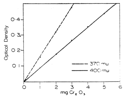
Fig. 1. — Optical density of chromate solutions expressed Cr2O3
DETERMINATION OF CHROMIUM SESQUIOXIDE IN FAECES
Procedure
The ashed sample containing 1 to 5 mg Cr2O3 is quantitatively brushed into a dry 100 ml wide-necked-Erlenmeyer flask which is graduated at 100 ml, and 6 ml of acid mixture is added. After bringing to the boil. 3 ml of 4.5% KBrO3 solution is added and boiling continued until 1/2 -1 minute after fumes of SO2 appear. The flask is removed from the hotplate, allowed to cool, then 20 ml of diluted KBrO3 solution added and the mixture boiled for 3-4 minutes, cooled, made up to the 100 ml mark and mixed. With pipette, 10 ml is transferred into a 25 ml graduated boiling tube, 5 ml 10% NaOH solution added and heated in a boiling water bath for a few minutes to allow the MnO2 precipitate to settle. The solution is cooled, brought to volume, and inverted gently once (see Note 4). Sufficient is filtered through a No. 40 Whatman filter paper and the absorption is read at wavelength 400 mμ. A blank is run on Cr2O3 free faeces and reagents. For the standard curve a solution of 2.555 g K2CrO4/litre is used. (1 ml = 1 mg Cr2O3).
Reagents
| Acid Mixture: | 250 ml conc. H2SO4 |
| 250 ml H3PO4 (sp. gr. 1.75) | |
| 500 ml distilled water | |
| 50 ml 10% solution MnSO4, 4H2O | |
| Dilute Bromate Solution: | 50 ml 4.5% KBrO3 solution |
| 450 ml distilled water |
Notes on Procedure
Sufficient quantity of MnSO4 must be present, but excess does not interfere. It would appear that the manganous sulphate is oxidised by the bromate to permanganate which in turn oxidises the Cr2O3. In Coup's long-boiling method with the acid solution diluted and kept constant at 40-50 ml the MnSO4 acts essentially as a catalyst, but in this method the MnSO4 is more expendable with the formation of MnO2 precipitate.
fter the initial digestion by heating until the sulphuric acid fumes, then addition of dilute bromate solution, the volume must not be allowed to drop or reduction occurs. With only 3-4 minutes boiling at this stage there is no need to replenish the water. Boiling for longer periods gives lower results probably owing to reduction of the dichromate as the acid becomes more concentrated. This can be noted by a change in colour from deep brown to milky light brown.
Iron and other metals present in the ash help, with heating, to change the MnO2 precipitate in the alkaline solution from the colloidal form, which passes through the filter paper, to a heavier flocculent precipitate. It is found that the addition of faeces ash to the standard potassium chromate solutions gives a better reproducibility and recovery (see Table 2). The amount of chromate lost in the MnO2 and other precipitates is negligible.
It is important not to shake the final solution before reading, as the MnO2 precipitate is readily broken down again into the colloidal form.
Recovery Tests
Commercial chromic oxide, used in the preparation of capsules, was assayed for purity by this wet digestion colorimetric method (W.D.C.) and that of Christian and Coup (1954). A comparison of the mean results and standard deviations is shown in Table 1 (0.3 g faeces ash was added to each sample).
TABLE 1. PURITY OF Cr2O3
| Method | Sample | Range % | Mean | No. of Assays | Standard Deviation |
| Christian and Coup | No. 1–59 | 96.8–98.2 | 97.7 | 8 | 0.55 |
| W.D.C. | No. 1–59 | 97.6–99.0 | 98.2 | 8 | 0.55 |
| Christian and Coup | No. 30063 | 97.1–98.6 | 98.1 | 8 | 0.47 |
| W.D.C. | No. 30063 | 98.3–99.2 | 98.7 | 8 | 0.38 |
Table 2 shows results as percentage recovery from samples which were made in the laboratory as follows:
Known amounts of K2CrO4 added to dried ground faeces.
Known amounts of K2CrO4 solution (2.555 g/litre, 1 ml = 1 mg Cr2O3) taken through the digestion procedure.
As (b), but with approximately 0.3 g faeces ash added.
TABLE 2. Cr2O3 RECOVERY %
| Sample | Mg Cr2O3 Assayed | Mean | |||
| 2 | 3 | 4 | 5 | ||
| a | 99.7 | 102.0 | 100.4 | 98.9 | 100.3 |
| b | 99.8 | 104.0 | 103.8 | 98.8 | 101.6 |
| c | 100.7 | 99.9 | 99.7 | 99.8 | 100.0 |
Faeces samples from four grazing cows dosed with Cr2O3 were assaved in duplicate with the normal daily batch by two different technicians (T1 and T2) to compare between-operator variability on a routine basis. The results are shown in Table 3.
Thus the wet digestion colorimetric method shows greater reproducibility and higher recovery. The daily output can be increased from 36 to 48 estimations without lowering reproducibility which is high to within 2%. The method is recommended as a rapid and reliable procedure for large-scale routine work.
TABLE 3. BETWEEN-OPERATOR VARIABILITY
| Sample No. | Christian & Coup | W.D.C. | ||
| T1 | T2 | T1 | T2 | |
| 48/300 | 4.88 | 4.53 | 4.80 | 4.83 |
| 50/275 | 10.11 | 10.34 | 10.30 | 10.42 |
| 39/300 | 5.59 | 5.31 | 5.69 | 5.81 |
| 26/318 | 3.67 | 3.93 | 4.13 | 4.16 |
REFERENCES
Barnicoat, C.R. 1945: N.Z.J. Sci. Tech. A27: 202-12.
Christian, K.R.; Coup, M.R. 1954: Ibid: A 36: 328
Coup, M.R.; Lancaster, R.J. 1952: Ibid: A 34: 347-53
Edin, H.; Kihlen, G: Nordfeldt; S. 1945: Ann. R. agric. Coll. Sweden. 12: 166-71.
Kameoka, K.; Yoshida. M Kubato, D.; Takahashi, S. 1957: Bull. Nat. Inst. agric. Sci. G.13
Kane. E.A.; Jacobson, W.C.; Moore, L.A. 1950: J. Nutr. 41: 583-96.
Maunsell. P.W. 1944: N.Z. J. Sci. Tech. B 26: 94-8
Raymond, W.F.; Minson. D. J. 1955: J. Brit. Grassl. Soc. 10, 4: 282-96
Sandell, E. B. 1950: “Colorimetric Determination of Trace Metals” Vol. 3. 2nd ed. Interscience Publishers Inc., New York.
Schurch. A. F.; Lloyd. L. E.; Crampton, E. W. 1950: J. Nutr. 41: 629-36.
| Ingredient | % | g/kg |
| Fish meal | 20.0 | 200 |
| Soybean meal | 11.0 | 110 |
| Shrimphead Meal | 18.0 | 180 |
| Casein | 7.5 | 75 |
| Glutinous Rice Flour | 33.0 | 330 |
| Squid Liver Oil | 3.0 | 30 |
| CMC | 1.5 | 15 |
| Minerals Mix* | 2.0 | 20 |
| Vitamins Mix | 2.0 | 20 |
| Choline Chloride (50%) | 2.0 | 20 |
* Mineral mix is 50% mineral mix, and 50% disodium phosphate.
Approximately 650 mL of boiling water was added to diets which were made without pre-cooking the starch component (glutinous rice flour, tapioca flour, etc.)
When the starch component was pre-cooked before mixing, it was mixed with cold water and then heated over a hot plate until gelatinized.
| Formulation | 1 | 2 | 3 | 4 | 5 | 6 |
| % | % | % | % | % | % | |
| Fish Meal | 8.0 | 15.0 | 13.6 | 10.5 | 32.33 | 28.2 |
| Soybean Meal | 48.0 | 40.0 | 10.9 | 17.0 | ||
| Full-fat SBM | 47.6 | 51.7 | ||||
| Corn | 31.0 | 20.0 | 5.0 | |||
| Broken Rice | 30.2 | 35.0 | 7.0 | |||
| Rice Bran | 10 | 8.0 | 10.0 | 38.0 | 34.9 | |
| Oil | - | 3.0 | 4.0 | 10.0 | 9.1 | |
| Minerals | - | 1.0* | 0.6 | 0.6 | 0.6 | 0.6 |
| Vitamins | - | 0.5 | 0.5 | 0.5 | 0.5 | |
| Dicalcium Phosphate | - | 2.7 | 2.7 | 2.7 | 2.7 | 2.7 |
| Vitamin C | - | 0.1 | 0.1 | 0.1 | 0.1 | 0.1 |
| % Crude Protein | 32.0 | 32.0 | 32.0 | 32.0 | ||
| % Lipid | 10.29 | 17.43 | 18.77 | 17.36 | ||
| % NFE | 45.2 | 37.34 | 30.76 | 28.59 | ||
| % Fiber | 3.29 | 4.48 | 5.55 | 5.96 | ||
| % Ash | 7.01 | 7.50 | 12.63 | 11.94 | ||
| % Lys | 2.16 | 2.11 | 2.33 | 2.29 | ||
| % Met | 0.63 | 0.6 | 0.4 | 0.8 | ||
| % Cys | 0.44 | 0.46 | 0.33 | 0.34 | ||
| % Arg | ||||||
| DE (Kcal/kg) | 3380 | 3372 | 3353 | 3365 | ||
| CP/DE ratio | 10.6 | 10.5 | 10.5 | 10.5 |
* Better Pharma mineral/vitamin premix for fish
| Formulation | 1 | 2 | 3 | 4 |
| % | % | % | % | |
| Fish Meal | 18.4 | 15.0 | 12.0 | 19.2 |
| Soybean Meal | 46.0 | |||
| Peanut Meal | 38.8 | 43.5 | 37.0 | |
| Broken Rice | 32.0 | 26.7 | 18.7 | 18.0 |
| Cassava | 10.0 | 10.0 | ||
| Rice Bran | 5.0 | 8.0 | 8.0 | 10.0 |
| Oil | 2.0 | 3.0 | 1.5 | 2.0 |
| Minerals | 0.5 | 0.5 | 0.5 | 0.5 |
| Vitamins | 0.5 | 0.5 | 0.5 | 0.5 |
| Dicalcium Phosphate | 2.7 | 2.7 | 2.7 | 2.7 |
| Vitamin C | 0.1 | 0.1 | 0.1 | 0.1 |
| % Crude Protein (wet wt) | 30.0 | 30.1 | 29.9 | 29.9 |
| % Lipid (wet wt) | 6.2 | 7.4 | 5.9 | 6.7 |
| % NFE (wet wt) | 39.5 | 38.1 | 39.0 | 37.9 |
| % Fiber (wet wt) | 3.6 | 4.0 | 3.6 | 3.5 |
| % Ash (wet wt) | 9.4 | 9.9 | 8.1 | 10.1 |
| Lys — % of CC Req* | 100 | 93 | 127† | 100† |
| Met — % of CC Req | 84 | 78 | 79 | 83 |
| Met + Cys — % of CC Req | 138 | 133 | 130 | 135 |
| Arg — % of CC Req | 192 | 195 | 155 | 185 |
| Phe — % of CC Req | 89 | 89 | 92 | 86 |
| Phe + Tyr — % of CC Req | 161 | 160 | 165 | 155 |
| Trp — % of CC Req | 207 | 207 | 242 | 207 |
| His — % of CC Req | 145 | 145 | 162 | 142 |
| IIe — % of CC Req | 168 | 165 | 208 | 164 |
| Leu — % of CC Req | 195 | 191 | 221 | 193 |
| Thr — % of CC Req | 168 | 163 | 192 | 166 |
| Val — % of CC Req | 166 | 163 | 172 | 163 |
| DE(Kcal/kg) (wet wt) | 2529 | 2580 | 2501 | 2539 |
| CP/DE ratio | 8.4 | 8.6 | 8.4 | 8.5 |
* % of channel catfish requirement
† amino acid calculations assume no contribution from cassava
![]()
![]()
![]()