![]()
![]()
![]()
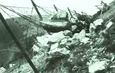
The first technical avalanche defence works in the starting zone were erected in France in 1842. In Baréges (Pyrenees) an attempt was made to imitate the effect of forestation by planting metal stakes into the ground in the starting zone; this was not, however, very successful.
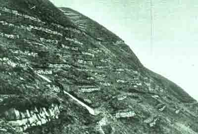
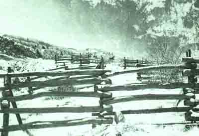
Similar efforts are reported in Switzerland (Schleins commune in GR) in 1867, where the forest in five precipitous gorges had been destroyed, and it was not possible to reforest them. An attempt was therefore made to contain the snow by building 19 free standing walls and 17 rows of wooden stakes.
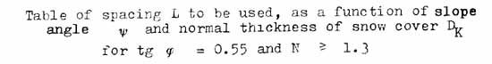
By 1881 we find that Coaz already draws a distinction between permanent structures (walls) above the forest line, and temporary defences of rows of wooden stakes (1.5-1.6 m. long, ø 15 em., Preferably quartered logs as opposed to round stakes sunk vertically to half their length into the ground and 60 em. apart) or even snow rakes.
Construction is begun in the area of release working downwards; the stakes are placed in horizontal rows, theoretically wherever a gentle slope steepens. If the slope is even the stakes are placed on artificial terraces 50-60 em. wide. The stakes at the ends of rows are larger and stronger than the rest.
Coaz also mentions the construction of a windbreak to prevent the formation of cornices near the Albula Pass; it consisted of rows of thin poles some 6 m. long.
As far as rakes were concerned, these were designed in much the same way as their modern counterparts.
Solid structures: Dry stone walls have no earth-fill behind them; they measure 60 cm. at their coping and they stand 1 m. high on the up-hill side - however, if necessary they can be built higher. The structures should be staggered in order to reduce their cost.
Coaz recommends that these structures should be adapted to the terrain but he does not specify the required distance between rows. He is most insistent, though, on an annual inspection of the works so that any maintenance can be carried out.
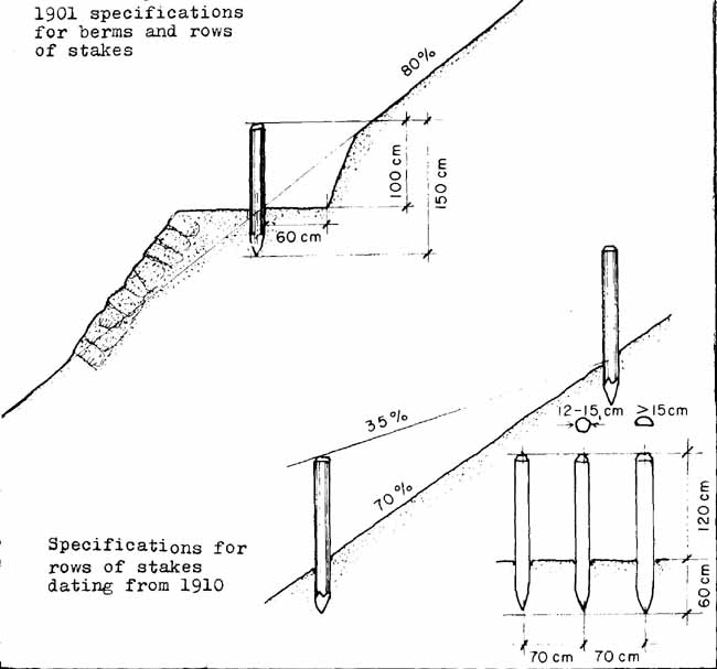
It is according to these specifications that our forebears built defences over the decades with varying degrees of success (for example in Switzerland 1 000 km. of avalanche defence structures were built between 1876 and 1938, 95 percent of which were solid structures). By introducing formulae to determine the distance between rows and by experimenting with all the various materials, scientific guidelines have emerged which now enable us to site the structures more accurately through calculation, and thus obtain greater rates of success.
This evolution can be followed for all large areas of avalanche defence works, and the structures can thus be dated from their design.
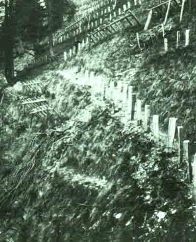
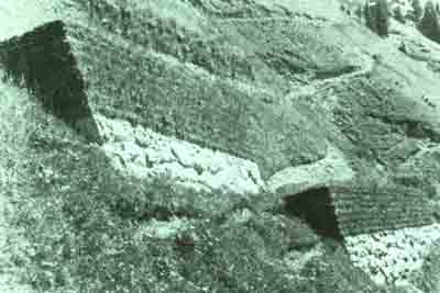
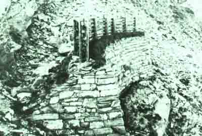
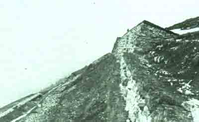
Basically this evolution has entailed the transformation of the wall into a horizontal walled terrace, then to walled terraces with a reverse slope (for these terraces proved themselves to be more effective and to offer greater resistance to snow creep than did walls). In areas of great snow fall, walls had to reach prohibitive heights (up to 9 m. high) and also have the added drawback of becoming rapidly filled up with snow. Elsewhere, poor rock presented practically insurmountable problems and so attempts were made to resurrect Coaz's other idea: the rake. However, more appropriate materials were used such as old railway rails, sleepers, etc.
Later, the Swiss Forestry Service, conscious of the gaps in available knowledge, and in view of the importance and the variety of problems and their repercussions on the economy of mountain regions, realized that systematic and fundamental study of snow and avalanches was necessary. The first publications of the Swiss Institute at Weissflujoch (where research began in 1935) date from 1939, and it is among these early publications that we find, among others, R. Haefelils calculations of snow pressure.
In 1942 the actual building which now constitutes the Institute was completed, and in 1947-48 the publications by its first director, E. Bucher, had an enormous influence on design and construction of avalanche defences, especially after the disastrous winter of 1951.
The following are the main materials now used in avalanche defence works:
- snow bridges made of prestressed concrete,
- snow bridges and snow rakes made of aluminium alloys or steel,
- steel or nylon netting,
- and finally snow rakes made of impregnated wood.
Between 1938 and 1966 117 km. of defence structures were built in Switzerland, of which 82 percent were mixed snow stabilization schemes.
Today there are several research centres and institutions distributed throughout the Alpine region. These are:
Austria:
Institut fur Wildbach- und Lawinenverbauung
hochschule fur Bodenkultur
A-1190 Wien, Peter Jordanstrasse 82
Institut fur Wildback- und Lawinenverbauung
A-1140 Wien, Hadersdorf Mariabrunn
Institut fur Wildback- und Lawinenverbauung
Forstl. Bundesversuchsanstalt Mariabrunn
A-1130 Wien, Mariabrunn
Spain:
Institute Nacional para la Conservación de la Naturaleza
Mayor, 83
Madrid-13
Instituto Nacional de Investigaciones Agrarias
Puerta de Hierro s/n
Madrid-35
France:
CTGREF (Division Nivologie)
B.P. 114
F-38402 St.Martin d'Héres
Italy:
Universitá di Torino
Istituto di geografia alpina
Centro studio valanghe
1-10124 Torino
Servizio Valanghe del Club Alpino Italiano
Via Ugo Foscolo 3
20121 Milano
(particularly for the forecasting and warning service)
Gruppo Neve e Valanghe del Comitato
Glaciologico Italiano
Via Accademia delle Scienze 5
Torino
Switzerland:
Institut federal pour l'etude de la neige et des avalanches
CH-7260 Weissfluhjoch-Davos
Walls are almost never used nowadays, for their cost is entirely disproportionate to their efficacy, and furthermore their upkeep is extremely costly. For this reason we will only examine modern and effective structures here.
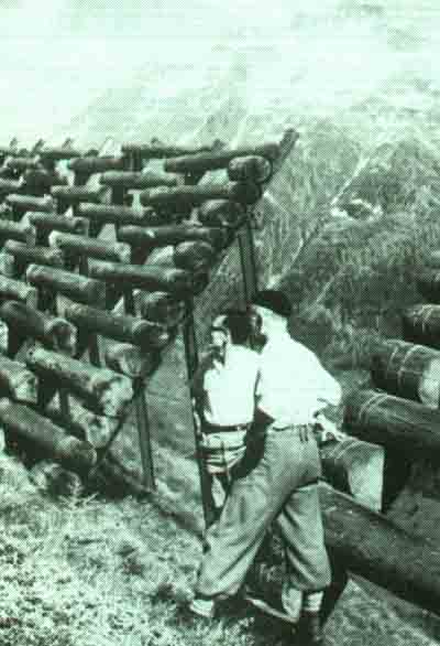
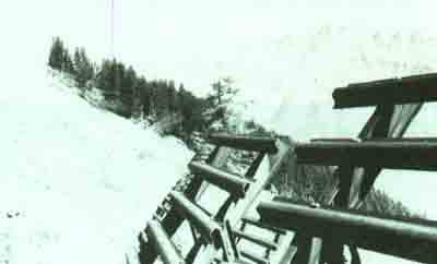
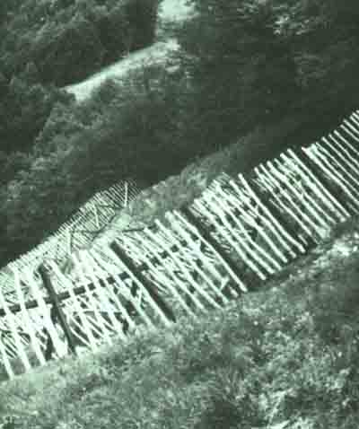
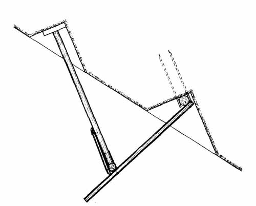
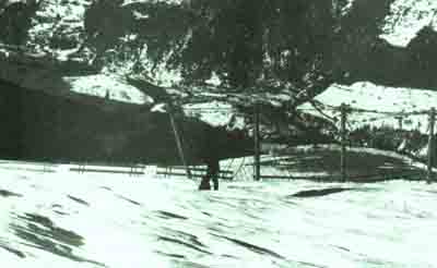
We must first draw a distinction between snow bridges and rakes. Snow bridges are less effective on a theoretical level than rakes, for it is easy for a small avalanche to pass between their bars. On the other hand though they are easier to build and less costly overall. They can be built from various materials.
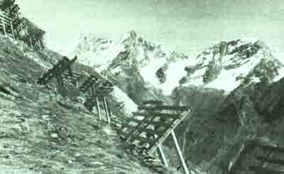
Photo No. 28
Example of snow bridge. The frame is made of old railway track and the superstructure is
made of round timbers.
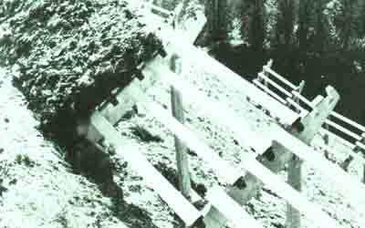
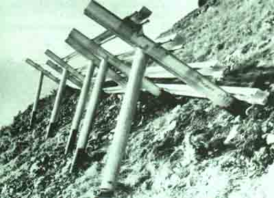
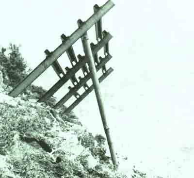
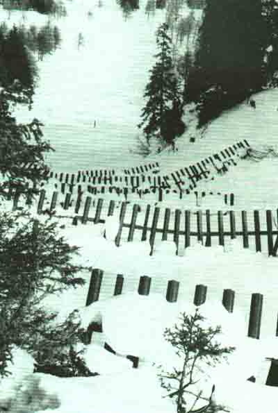
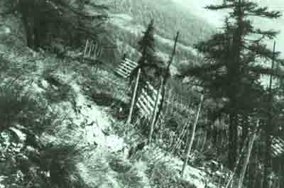
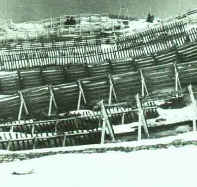
Rakes offer the theoretical advantage of supporting all the strata of snow since the bars are placed vertically. In practice their construction is much more difficult and generally they are more expensive than bridges. The same materials can be used in their construction.
Examples of snow rakes
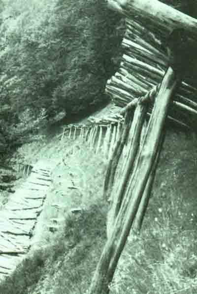
Examples of snow rakes
There are various conditions which must be fulfilled for such structures to be used:
- a layer of topsoil covering solid rock which affords strong anchoring points,
- exposure to the sun which produces quick snow metamorphosis (placed in the shade where snow remains powdery for a long time this type of structure has already been known to have caused a few setbacks). Wherever there is some doubt these flexible structures can be used in combination with their rigid counterparts.
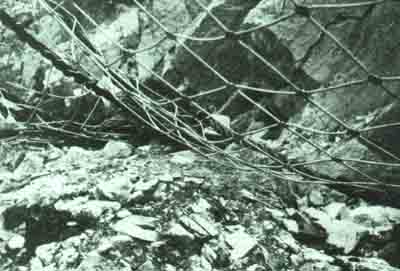
Because of their suppleness, nets have been found to offer the advantage of being unaffected by stone fall and small localised snow slides.
From the esthetic point of view, nets are barely noticeable during the summer months.
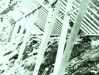
Examples of net avalanche defences:
Before these can be listed we must examine the aims and effects of the construction of these defences as defined in the guidelines.
These guidelines allow a certain freedom with regard to the size and positioning of the structures. This freedom must be used in order to adapt the avalanche defences to the requirements of the objects under protection - i.e. to adapt them to the acceptable levels of risk.
In order to take account of these requirements we must not only consider the type of object being protected (e.g. whether it is inhabited or not), but we must also consider its position in relation to the starting zone, the trajectory and the deposit zone (thus if the object is directly in the path of an avalanche its protective requirements will be correspondingly higher).
The effect of these stabilizing structures is to oppose snow creep and glide by presenting a support surface which is more or less perpendicular to the steepest part of the slope on to which it is anchored, and which is higher than the level of snow. This effectively produces an "arrest", that is to say, the speed of creep and glide reduce the closer the snow is to the structure. In this compression zone above the structure, which in practice extends over a distance parallel to the slope of at least three times the vertical height of the snow (the distance over which the effect is felt is a function of snow creep), there are additional compression forces acting parallel to the slope. These forces are absorbed by the structure thus reducing the tensile and shear stresses above it, stresses which would favour the release of a slab avalanche.
Where there is a slide of snow between the defense structures, these prevent old layers of snow from being-carried away too, and they also limit the area over which a shear fracture could spread . By their braking effect, the structures reduce the speed of the slide - speed is the fundamental factor in determining damage. Finally, the intercepting power of these structures is beneficial.
Stabilizing structures can be used in either a temporary or permanent capacity. An exception must be made, though, for structures made of wood or of new plastic materials the behaviour of which is not fully known, in particular with regard to their deterioration when exposed to the elements.
Under these conditions wooden structures can be used providing they will be replaced by sufficiently mature forest when they begin to rot.
Metal structures which are articulated to their foundations in such a way as to permit their dismantling can also be used in this capacity.
Chapter II described snow as a material. Before dimensions can be specified for the structures, the forces which this deformable material can exert on the structure must be known. The guidelines which follow are the result of research undertaken at the Institute at Weissfluhjoch.
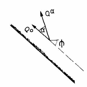
The fundamental pressure exerted by snow on a plane vertical to the line of gradient and on a plane perpendicular to it is composed of:
- pressure due to localized resistance to creep and glide,
- pressure due to resistance to lateral plastic dilation caused by the snow's own weight perpendicular to the slope (nivostatic pressure).
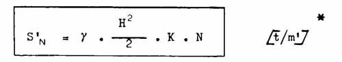
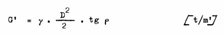
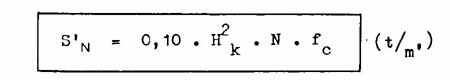
The fundamental pressure exerted parallel to the slope by snow against a section of a support surface of indefinite length placed perpendicular to the slope is expressed by the following equation - which ignores nivostatic pressure:
![]()
S'N is usually regarded as being uniformly exerted over the whole height of the defence superstructure (thus simplifying the complex distribution of pressure in the snow cover even when it is homogeneous).
Nivostatic pressure is normally ignored with regard to pressure created by the braking of creep and glide.
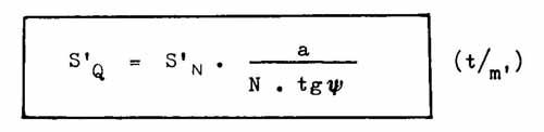
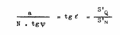
This component of pressure which is perpendicular to the slope and is exerted on a rigid surface also perpendicular to the slope, is manifested when consolidation is impeded by that surface (either by adherence or roughness) and corresponds to:
where:
S'Q = component of fundamental pressure exerted by snow perpendicular to the slope
E = vector of fundamental pressure of snow with relation to the line of gradient
a= coefficient dependent on snow quality (varying between 0.2 and 0.5)
In the same way S'Q is regarded as being uniformly exerted over the whole height of the defence superstructure.
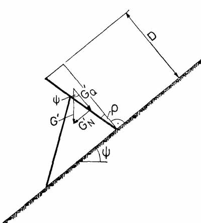
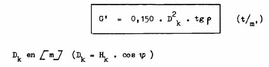
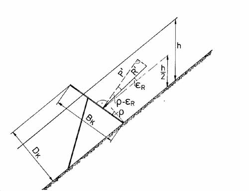
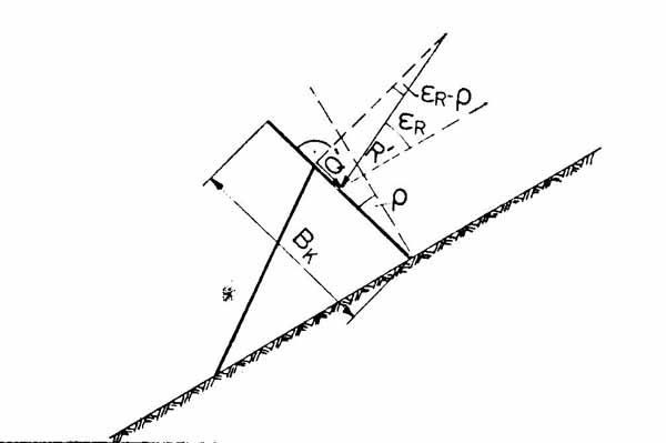
When the support surface of the structure is not perpendicular to the slope the weight G' of the prism of snow held between the surface of the structure and the perpendicular must be added to the fundamental pressures S'N and S'Q . The perpendicular in the case of a downward lean passes through the intersection of the defence superstructure and the soil. In the case of an uphill lean the perpendicular passes through the upper edge of the support surface of the defence structure (vertical barrier).
The extra load caused by the inclination of a flat support surface is:
where:
G, = extra load due to the inclination of the superstructure = weight of prism of snow per
unit length
D = thickness of snow
p = inclination: angle formed by the surface of the structure and the perpendicular to the slope
G'N , G'Q = parallel components of G' in relation to the perpendicular of the slope
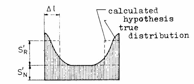
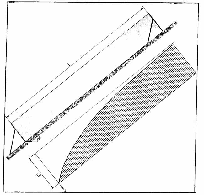
If the surface of the defence structure is of limited length an additional load is exerted on the extremities of the structure due in part to the fact that snow can flow around its ends, and in part to the braking effect produced in the layers of snow beyond the sides of the structure. These marginal forces depend on all the factors which determine the pressure of snow against a structure of infinite length, as well as on the size, shape and roughness of the superstructure, and especially also on the snow glide. Figure 25 shows the distribution of snow pressure. In practice, the marginal loads integrated over the whole length of the structure are replaced by a marginal load constant equivalent to S'R which is distributed over the marginal strips of the superstructure of width 1 measured from the two extremities.
The degree of efficacy n of a stabilizing structure (relative to the loads borne) is defined as the ratio between the effective pressure of snow (including marginal loading) and the fundamental pressure of snow (excluding marginal loading).
Due to irregularities of terrain and distribution of snow, the resulting vector of all the pressures exerted on the support surface of the structure is not always in a plane perpendicular to this surface. To take account of this, allowance is made for lateral stress SS parallel to the contour lines.
Article 1 of Chapter IV of the guidelines defines the role of these permanent structures. Theirs is a dual function: primarily they increase the general stability of the snow cover of a slope, i.e. the ratio between cohesion and the stresses present. Their secondary function is to limit the volume of snow which could be set in motion, as well as to slow down and possibly intercept this snow.
How is this increased stability of the layers of snow on a slope obtained? The stresses in this case are created entirely by the snow's own weight. These, as long as the slope is regular, are transmitted from one stratum to another as shear and vertical loadings right down to the ground. When irregularities in the slope produce a more complex relief, part of the stress is transmitted to the various obstacles such as rocks, trees and areas of gentler gradient by the vector of stress running parallel to the slope. With new snowfalls, tension increases at a rate proportional to the intensity of the snowfall. In order to prevent stability from becoming critical as it approaches a value of l, cohesion must increase correspondingly. As we know from experience, it is usually the shear strengths and the shear stresses parallel to a layer of snow that determine whether the release of an avalanche occurs or not. Certain strata of snow (such as surface hoard or depth hoard) may be relatively weak with respect to the rest of the snow cover. Stability is increased by the vertical loads which produce an increase in shear strength and also compression. But if a localized shear fracture is formed despite this process, this will extend until it reaches an area of high stability such as a gentler gradient or an area of high shear strength. In the case of a slope where the areas of high stability are far apart, a slab avalanche produced under these conditions could reach large proportions.
The construction of rigid support surfaces for snow to push against dramatically alters the conditions on a slope covered with snow.
The downhill movement of snow (the properties of which are similar to those of fluids - see Chapter II paragraph 1) is slowed up by these structures, producing complementary forces of compression above them over a distance determined by the equation o = 1/a . o u / ox
These complementary forces absorb part of the dangerous shear stresses. The main effect of these stabilizing structures thus consists of changing the shear stresses, and possibly tensile strains, into compression.
The guidelines established by the Weissfluhjoch Institute for the calculations pertaining to stabilizing defences are presented here, for they are already in use in several countries of the alpine region.
The formulae and calculations reported here pertain to framed structures with a rigid superstructure perpendicular to the slope, or inclined by angle P in relation to the perpendicular. Except for a few restrictions the calculations also apply to structures with a slack superstructure.
a) Wood
Squared timbers are used of standard SIA No. 163.
Round timbers and thinner rods must be in good order with no obvious faults, particularly twisted fibres, knots and compressed wood. If need be, the admissable loads for squared timbers of type III can be used, so long as a certain tolerance is allowed in their selection.
The durability of wood can be increased by treating it in various ways. Surface treatment such as charring, brushing, spraying or rapid soaking of the pieces used for construction is not satisfactory. A successful treatment depends rather on a variety of factors, such as on the sap, the state of the wood, the method of assembly and the climate in the area. Following the results obtained in several experiments (carried out in different areas) SFISAR recommends adequate means of protection and gives instructions for their application.
Beech and ash must not be used unless they have been impregnated (e.g. with creosote under pressure).
Untreated spruce and fir have a very short life expectancy and can only be used for between three and ten years, depending on the method of construction, the placing of the structures, altitude and climate. Some form of protective treatment is therefore essential.
Untreated larch, pine, chestnut or oak can be relied upon for anything up to 25 years or more under conditions of avalanche defence.
b) Steel
The following types of steel must be used for constructions whether they are welded or not.
For the frame (supporting pillars, uprights and longitudinal beams) one must use steel of grades 37-3, 42-3, 52-3 DIN 17 100 (September 1966). The specifications presented here do not take other types of steel into consideration.
For the superstructure the guidelines mention only the following grades: 37-2, 37-3, 42-2, 42-3, and 52-3 DIN 17 100 (September 1966).
Grades 50-2 and 60-2 DIN 17 100 can also be used for non-welded components of the superstructure.
c) Light alloys
Aluminium alloys which fulfill the standards DIN 4113 of February 1958 must be used.
With regard to the degree of safety, a distinction is drawn between the foundations (infrastructure) and the frame and superstructure (the structure).
Foundations are calculated in such a way that the maximum force exerted on them by the soil will not exceed 50 percent of their breaking strain.
The frame is designed to be solid and durable, provided of course that it is adequately
maintained over the years.
Greater strains can be allowed in the superstructure than in the frame because the
crossbeams of the former can be replaced easily.
a) Basic rules
Unless otherwise indicated all standards are SIA. The following rules apply only to avalanche defence structures which stabilize snow in the starting zone; they do not pertain to structures intended to deviate or slow down avalanches, still less so to structures designed by civil engineers such as bridges, etc.
Contrary to SIA standards only the "maximum stress allowed" is determinant. "Maximum deformation allowed" is not taken into account.
The creep of metals and the stresses allowed have all been established (including the frequency of the effects of snow pressure).
For the loads adopted refer to sections 4.2.6 to 4.2.9.
b) Wooden structures
Principles:
The minimum section of wood must always be determined by calculation and adhered to rigorously. If larch, chestnut or oak are used only the cross section of the hard core is incorporated into the calculations unless the sap wood has received adequate protective treatment.
Frame:
Squared timbers - Contrary to the reduction in "stress allowed" (60 percent) specified in Section 5 Article 9 of SIA 164 the "stress allowed" is reduced to 70 percent of the original.
Round timbers and poles - The "stress allowed" for both longitudinal compression and bending round timbers and poles can be increased by 25 percent over the allowance made for grade II squared timbers.
The maximum "stress allowed" for wood including the modifications mentioned here are presented in tabular form below.
Superstructure:
Contrary to the rule stated in the first paragraph under "Frame" the #@stress allowed" is reduced to 80 percent.
The "stress allowed" for wood used in the frame can be increased by 25 percent for wood in the superstructure. The values will be found in the table below.
c) Steel constructions
General comments:
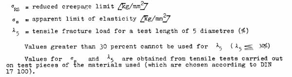
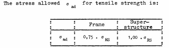
"Reduced creep limit" o RS ) is used here to signify a value for the strength of the material obtained by introducing an empirical coefficient. This coefficient is obtained from the correlation between the apparent limit of elasticity and the tensile fracture load which is obtained experimentally.
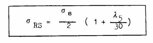
where:
A separate test must be carried out for each group of constructions and for each portion of 200 m. at most of sections.
Tests for buckling, bending and warping will be carried out according to the SIA standards for class II structures under load Z.
The sections used must be those that were used in the calculation; those pieces which are seen to have a lower resistance to buckling than calculated must be discarded.
Rust is compensated for by allowing an extra 0.5 mm. width on each exterior face. This extra width is eliminated for materials which have been galvanized.
Stress allowed:
The norm specifies the stresses allowed for buckling, warping and bending, but a load equivalent to 100 percent of the stress allowed produces creep in the material. This deformation, which is accentuated by the increasing turning movement of the loads and by a weakening of the section, reaches 0.5 percent; this must be allowed for.
where:
![]()
d) Construction with light alloys
General rule:
Calculations for structures made of light alloys are carried out according to DIN 4113 (February 1958) under load HZ. The following prescriptions must also be adhered to.
Load |
Stress allowed in kg/cm² |
|||||||
| Frame: including reduction by 70% | Superstructure: including reduction by 80% | |||||||
Squared timber |
Round |
Squared timber (SIA 163 grades) |
Round |
|||||
I |
II | III | I |
II | III | |||
| Bending, no axial force, stress allowed at the edge ðR |
||||||||
| Resinous | 85 |
70 |
50 | 90 |
120 | 100 |
70 |
125 |
| Hard wood | 105 |
97 |
65 | 110 |
150 | 127 |
90 |
155 |
| Compression and tension ²/ parallel to the fibres | ||||||||
| Resinous | 70 |
60 |
40 | 75 | 100 | 85 |
60¹ |
105 |
| Hard wood | 90 |
do |
50 | 95 | 125 | 105 |
75¹ |
130 |
| Buckling | According to Art.14 of SIA norm No.164 with reduction of 70% (Art-39) |
According to Art.14 of SIA norm No.164 with reduction of 80% (Art.42.1) |
||||||
| Compression perpendicular to the fibres | ||||||||
| Resinous | ||||||||
| Fixed at the end of the beam | 8 |
12 |
||||||
| Recessed | 11 |
16 |
||||||
| Hard wood | ||||||||
| Fixed at the end of the beam | 25 |
35 |
||||||
| Recessed | 35 |
45 |
||||||
| Shearing parallel to the fibres | ||||||||
| Resinous | 7 | 10 |
||||||
| Hard wood | 9 | 13 |
||||||
The figures which are not underlined need not be adhered to quite so strictly.
¹/ i.e. chestnut, oak, beech and ash
²/ Squared timbers of quality III cannot be used for elements that will be submitted to
tensile or buckling loads
Complementary prescriptions:
We must first ensure that the sections are identical to the ones used for the calculations. Sections which are seen to have a lower resistance to buckling must be discarded.
A separate test of strength must be carried out for each group of constructions and for each portion of 200 m. at most sections.
To determine the resistance to buckling, warping and bending the following tolerance factor, to take into account increased turning movement, will be used in addition to the DIN 4113 specifications.
| Load with relation to initial stress allowed | Deformation through creep over 30 years |
| 100 | ðad 2% |
| 80 % | ðad 1% |
| 60 % | ðad 0,3 % |
e) Concrete constructions
The SIA standards can be used for solid, reinforced or prestressed concrete. On the other hand the safety factor can be reduced by 25 percent for the superstructure.
f) Construction with cables
A coefficient of safety of 2 with relation to the breaking strain is used.
The structures must be examined regularly and carefully; we suggest that they are checked each year and any maintenance required should be carried out. Any damage found will thus be repaired in good time.
Particular attention must be paid to the state of wooden structures so that sections which have been weakened by insects and fungi can be replaced.
For rigid superstructures we recommend an inclination of p = 15° relative to the perpendicular.
For slack superstructures (nets) an angle p = 30° has been used with success. This angle is relative to the average plane constituted by a line through the points of attachment of the net to the ground and the upper points of attachment.
On very steep ground a smaller angle p than in the examples above must be chosen.
When Hk > (Hext ) Hk replaces (Hext ) for the calculations.
a) First example of loading
This example considers a case where the structure is completely covered with snow of extreme height Hk .The vector of fundamental pressure of snow parallel to the slope for that part of the structure free of marginal loads is expressed by:
where:
Hk = vertical height of the structure in metres
Hk = glide factor
fc = Hk altitude factor
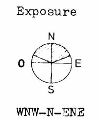
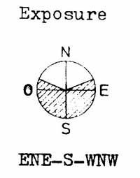
For an average specific gravity of snow: y H = 0.270 t/m³ - a fairly low value for standard altitude 1 500 m. and exposure WNW-N-ENE.
![]()
The vector of fundamental pressure of snow perpendicular to the slope is expressed by:
With regard to the direction of fundamental snow pressure expressed by E , the most unfavourable value is used.
The extra load caused by the inclination of the superstructure (weight of the prism of snow), including the increased specific gravity of snow against the surface of the superstructure, is expressed by the following equation, provided the surface is flat:
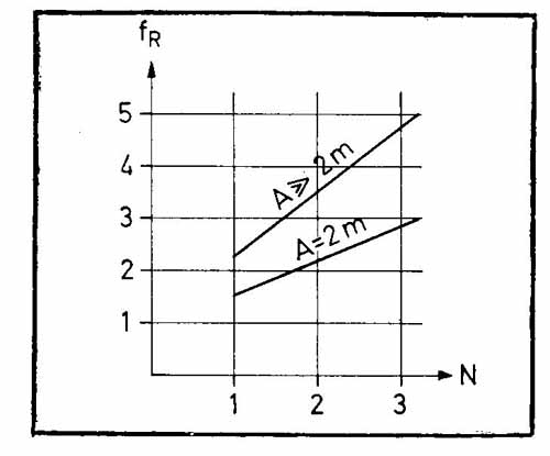
Marginal forces S'R are regarded as an extra load parallel to the slope distributed over the strips ( triangle recto ) 1. (No perpendicular component is allowed for with the marginal forces.)
S'R = fR . S'N
where:
fR = marginal factor
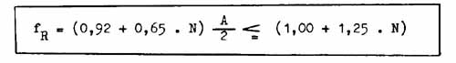
where:
N = glide factor
A = gap between structures in metres
The upper limit for fR holds for an isolated structure.
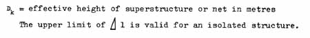
The length of application (triangle recto)1 of the marginal extra load S'R (width of marginal strip) is equivalent to:
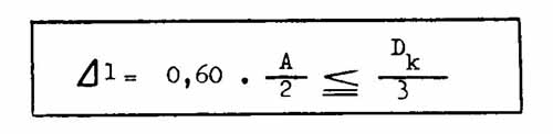
where:
When neighbouring structures are slightly staggered in relation to the gradient of the slope, the same marginal forces obtain as with structures which are not staggered. In certain cases, despite the different loads exerted on its extremities, a symmetrical structure will be required; in this case the structure is based on the greatest extra marginal load. This rule is particularly useful for small structures on the exposed side of a system of defences; all the more so since they are most exposed to dynamic snow movements.
The resultant value RI is obtained by vectorial addition of the parallel and perpendicular pressure components (in relation to the ground).
For a structure of infinite length the resultant is:
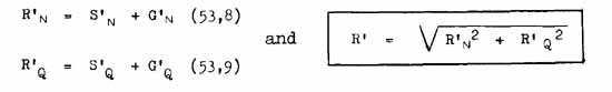

For the marginal strips where the extra loads are applied the extra marginal load S' R is added to the components S'N + G'N giving:
R'N = S'N = S'R = G'N
The direction of the resultant (in a plane perpendicular to the contour line) is obtained with the following formula:
where :
ER represents the angle formed between the resultant and a line parallel to the slope (R' does not have the same gradient at the margins of the structure where the extra marginal load is applied as over the rest of the structure).
It is assumed here that the fundamental snow pressure is applied at the centre of the maximum height of snow: H/2.
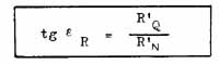
b) Second general example of loading
Partial snow cover:
In this case we consider the partial covering of a structure by snow of height h
h = 0,77 . Hk
and with a resultant of the same magnitude and direction as in the first example.
In relation to the first example of loading, the following differences should be noted:
- pressure from R' is applied lower: at height h/2 = 0.385 Hk and
- the pressure of snow Ph [t/m²] is higher (the factor has been raised by 1/0.77 = 1.3 Ph)
![]()
The conditions of snow cover used in the second example of loading are derived from the first due to the settling of the snow and to increase in the snow cover. The average specific gravity is also increased and is now
yh = 0.400 t/m³; it is valid for an altitude of 1 500 m. and a WNW-N-ENE exposure. It will be noted that yh . h> yH .Hk
c) Structure's own weight and lateral forces
The weight of the structure itself has to be taken into account, for it can be important.
To obtain sufficient lateral stability in the structures a further lateral force parallel to the contour line is incorporated. The following formula is used:
SS = 0,10 . S'N . l0
where:
l0= width of the section: horizontal distance between the two attachment points of the superstructure, of the longitudinal beams or of the net (distance between the two uprights, the two supporting pillars)
The lateral effort is applied at mid height of the superstructure. (We assume that the force is uniformly applied over the whole height of the superstructure.)
In defence systems composed of several sections (and particularly when the structures are arranged continuously) the lateral effort is applied to each section.
An effective transmission of this lateral effort from the superstructure to the frame and to the foundation, and between the various sections, must be ensured.
a) Loads perpendicular to the superstructure
The distribution of snow pressure against the support surface is often uneven under operational conditions, requiring us therefore to refine our hypotheses of the elements of load on the superstructure.
To determine the fundamental load on the superstructure we assume snow pressure as in the second general example of loading.
As seen in Figure 31 below, the breakdown of the load against a flat superstructure is given by the following formula:
P' = R'. cos (p - ER)
where:
P' = the resultant component of the load of snow RI perpendicular to the superstructure
ER = the angle formed between the gradient of the slope and the direction of R', and is calculated using a = 0.35.
The pressure of snow Ph perpendicular to the surface of the superstructure (flat) is therefore:
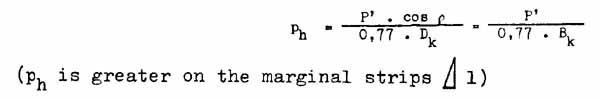
The linear load determining the calculations for the crossbeams, and acting perpendicular to the load-bearing width b is:
P B = Ph . b
where:
b = width of crossbeam plus a part of the neighbouring space (cf. Fig.34)
During the thaw, snow only pushes against the bottom of the superstructure. As a result, to the pressure calculated according to Article 55.2 we must add an extra load equivalent to 25 percent Ph for the whole length of the structure, and acting on a strip from the ground up to one quarter of the height of the superstructure (Figure 32).
For superstructures which might be subjected to marginal forces (cf. Fig = sup we must consider two types of determining loads:
- with extra marginal load S'R
- without extra marginal load S'R

b) Loads parallel to the plane of the superstructure (tangential pressure)
These tangential pressures vary mainly according to the shape of the superstructure. We therefore deal with them later when we examine the different types of structure.
c) Details of the calculations for crossbeams of snow bridges (bars parallel to the contour line)
Normal forces:
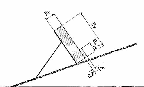
The requisite strength of the crossbeams is calculated according to the effective load-bearing width b. The uppermost crossbeam will be no weaker than the others. The effective width of load-bearing width b extends to the ground (cf. Fig.34)
Tangential pressures:
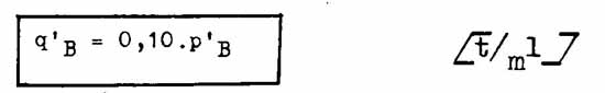
The requisite strengths of the crossbars and their attachment to the frame are calculated by assuming a linear pressure ± q' B which can be exerted both upwards and downwards without changing the absolute value (Figure 36).
In Figure 35 we see:
![]()
where:
Q'= the resultant component of pressure of snow R' exerted parallel to the plane of the superstructure
ER = the angle formed between RI and the gradient of the slope calculated with a = 0.5
Tangential pressure q h uniformly distributed is:
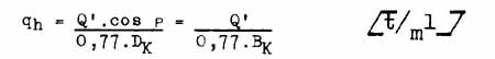
The linear tangential pressure which is determinant in calculations for the crossbeams is:
qB = qh . b
The minimal tangential pressure which must be accounted for is:
This prescribed minimum is almost always determinant when dealing with high values for the glide factor and for the inclination of the superstructure.
The tangential pressure is applied on the upper edge of the crossbeam (cf. Fig 36)
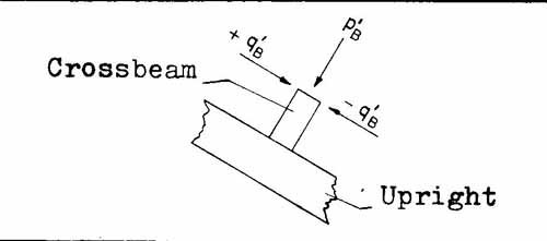
The normal pressure p'B is made to vary between its maximum value and the value of q'B keeping q'B as maximum. In this way we check that there are no forces which could damage the point of attachment of the crossbeam to the superstructure.
Tension produced in the bar by tangential pressure must be examined carefully.
Other provisions:
The gap between bars, and that between the lowest bar and the ground (w) must not exceed 30 cm. The uppermost bar must be attached particularly firmly to resist dynamic upward forces.
With structures with crossbeams of differing heights (e.g. bridges with alternating bars) the mean height of the beams is used to determine the effective height H.,
The length of a structure 1 is the mean distance between two lines joining the ends of the bars.
d) Details for calculations pertaining to the beams of rakes (beams perpendicular to the contour line)
Normal pressure:
The strength of the beams is determined in relation to the effective area under load b. The beam placed at each end is an exception; for the effective area of load is equal to the distance from the axis of the neighbouring beam but in addition these end beams are also subjected to marginal extra loads.
The area of effective load reaches the ground.
However, the extra 25 percent load (for snow bridges) does not apply to the crossbeams of the rake, but rather to the lower longitudinal beam.
As with the description for snow bridges we use here the second general example of loading to serve as the base for our calculation.
Tangential forces:
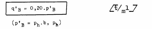
The most unfavourable tangential force is taken to serve as the basis for our calculations: a linear force applied to the upper edge of the beam parallel to the contour line in the plane of the superstructure. This pressure is expressed in the formula:
where:
p'B =normal maximum pressure on the beam
(p'B = Ph . b, Ph defined on page 99)
Tangential pressure due to settling of the snow (component R' perpendicular to the slope) must be accounted for when attaching the beams to the frame.
Other provisions:
The gap between crossbeams (w) must not exceed 35 cm. The gap between the lower end of the crossbeam and the ground should not be greater than 20 Cm. The effective height of the structure H. is the average vertical distance between a line joining the upper ends of the beams and the ground.
e) Details for calculations pertaining to nets (loose support surface made up of cables)
Reduction of snow pressure. A reduction factor fS is introduced here to take account of the reduction in the component of snow pressure parallel to the slope due to the flexibility of the support surface. This reduction factor depends on a number of variables such as: glide of snow over the ground fs increases with N); the sag, shape and inclination of the net; the size of the mesh (the reduction factor fs approaches 1 with decreasing size of mesh and amount of sag of the net).
The fundamental component of snow pressure parallel to the slope is now:
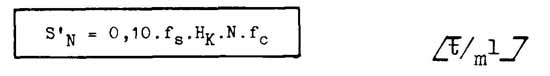
where:
fS = reduction factor for a slack superstructure
Hk = maximum height of snow at the site of the structure (in metres)
A conservative estimate for fS under normal conditions of glide would be fS = c. 0.8.
The strain borne by the net depends largely on the sag of the net; this must therefore be checked after assembling the structure and also after heavy snowfalls which may have produced slackening in the cables.
The component of snow pressure perpendicular to the slope need not be taken into account.
With regard to the extra load to inclination of the net G' the prism of snow ( ys = 0 .3 t/m³ ) is delimited by the surface of the net and the plane perpendicular to the slope which passes through the foot of the net.
Calculations for the stability of nets, and in particular for those elements which transmit the loads to the frame and the foundations, are determined by applying, with suitable modifications, the second general example of loading to the entire height of netting.
Uniform distribution of pressure over the whole height of the net acting parallel to the resultant R' is assumed.
The open spaces (w) should not exceed 25 cm. (mesh or spacing between elements in the netting system) even under full load. In fact this spacing has proved to be too large in practice and we suggest that the gaps should be reduced by superimposing a lattice with a minimum mesh of 8 cm. When using support surfaces made up of flat ribbons rather than nets the larger spacings can be applied (the efficacy is a function of the width of the ribbons).
The effective height of the structure Hk is equivalent to the mean vertical distance between highest and lowest point on the upper edge of the net and the ground. This measurement must be taken on a median component of the structure and under conditions of full loading.
The effective length of the structure 1 with netting in the shape of triangles or trapezia is equivalent to the mean of the length of the base and the length of the upper edge.
a) General examples of loading
The two general examples of loading as well as the lateral forces, are crucial for the calculations regarding the frame. Moreover, should it be necessary, account must be taken of whether loading occurs with or without extra marginal load SR
The strength of the elements used in construction fastened rigidly to the upper foundations, is calculated in relation to a point B which is regarded as the point of articulation. It is assumed that the section between ground level and point B is not under load.
Considerable liberty is allowed in the construction of the frame; freedom is also allowed regarding the geometry of the frame: inclination of the supporting pillar, the ratio for propping the superstructure, angle to the ground, size of the elements, etc. By considering only the external forces and the gradient of the slope optimal solutions will not be obtained, for these are also determined by the foundations. We draw attention to the fact that even on slopes of variable gradient the same reliability for all-he elements (and for the foundation can be maintained appreciably by keeping the angles between supporting pillar, superstructure and ground constant.
b) Particulars of the calculations for the frame of rakes
To calculate the force against the bottom longitudinal beam of a rake due to pressure exerted perpendicular to the superstructure, the second general example of loading is applied: extra load at -round level = 25 percent Of Ph
c) Particulars of the calculations regarding nets
By way of extra safety one must add to the axial pressure in the calculation for the strength of the articulated supporting pillars a transverse force due to the pressure of the snow going through the mesh, and to the adherence of snow below the net. This is represented by a linear force q' uniformly distributed:

where:
n= degree of efficacy assumed to be 1
Hk= extreme height of snow in the immediate proximity of the structure (in metres)
Diametre and length of the supporting pillar in metres.
The direction of q'S is perpendicular to the axis of the supporting pillar (turned downhill only, if the pillar cannot turn on its axis).
The transverse force is applied to the axis of the supporting pillar.
If as a result of the construction of the articulation the soil exerts an eccentric force on the supporting pillar, such eccentricity must be taken to be maximal.
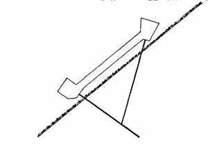
a) Types of foundation
Rigid structures:
Generally two separate bases are used: an upper base (base of the up right or and a lower base of the supporting pillar) (cf. Fig.37).
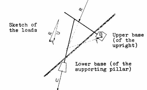
If the structure is to be built on light, running or weak soil, we recommend that the two foundations bases are joined with a tie-bar or with a girder which will resist both traction and compression (cf. Fig. 38)
Loose and special structures (palisades or fences, moored structures, etc.):
Where anchoring on to rock is possible, the pressure of snow can be counteracted with mooring cables.
b) General comments on the calculations required for foundations
The two general examples of loading as well as the lateral force are determinants in the calculations for the foundations.
In the following calculations it is assumed that the sole-plates placed in a superficial layer at least 50 cm. thick (measured perpendicular to the ground) are not themselves supported.
The admissible compression of the earth, parallel to the slope, will be determined by standard means (compression tests) accompanied, if necessary, by percussion profiles (see p. 115).
The admissible pressure loads in the soil depend on the direction of the force exerted. The table below gives admissible values as a function of the direction of the force in a plane vertical to the line of the steepest gradient.
a = the angle between the direction of the load and a line parallel to the slope
ðo ad = the admissible pressure load in the soil parallel to the slope
ða ad = the admissible load in the direction of the force (see Fig 39)
a |
0° |
15° | 30° | 45° | 60° | 75° | 90° |
ða ad / ðo ad |
1,00 |
1,32 | 1,66 | 2,0 | 2,26 | 2,43 | 2,50 |
This relation holds only for compression loads in the soil (when a is between 0° and 180° ). If traction forces are manifested, a foundation similar to that used for pylons is used instead (details on this matter appear in the following chapters).
With temporary wooden rakes of customary design the admissible forces of traction are very low.
These forces can be reduced to the maximum by the following means:
- where the glide factor is very high, by making the ground rougher (by building small berms or by planting stakes),
- by limiting the siting of such rakes to terrain of gentle gradient or to places where very large quantities of snow do not build up.
If such measures cannot be taken one can only use special traction resistant foundations or build permanent structures.
c) Fixing the frame to its base underground
In avalanche defence works embedding or jointing can, in principle, both be used.
For the upper foundation, jointing can only be considered if rock is on the surface, or if it is near enough to the surface for the fastening piton to be solidly anchored to it. On the other hand jointed fastening in the soil (in contrast to on rock) produces unfavourable forces in the soil and unacceptable deformation, or at least requires a volume of foundation work of uneconomic scale. For these reasons it is preferable to fix the upright to its base rigidly, which also makes it stronger. The superstructure cannot, however, be regarded as embedded in the ground, because the base plays the role of an anchored joint and is subject to internal movement in the soil (solifluction).
The supporting pillar can be jointed to the lower base without creating unfavourable compression in the soil and without requiring the base to be too voluminous.
Where the foundation bases are separate the supporting pillar is usually jointed to the upright (see Fig 37).
If, on the other hand, the bases are joined by a tie-bar, or if the structure is secured to rock (cf. Fig 38) it is not necessary to joint the supporting pillar and the upright.
Risk of corrosion of the construction elements must be guarded against when they are sealed in concrete, particularly with aluminium alloys.
d) Sealed foundations
Sealed foundations are prepared on the site of the structure (e.g. by casting concrete).
Compression of soil by upper foundations: (Dimensions of base as a function of the resistance of the soil to compression)
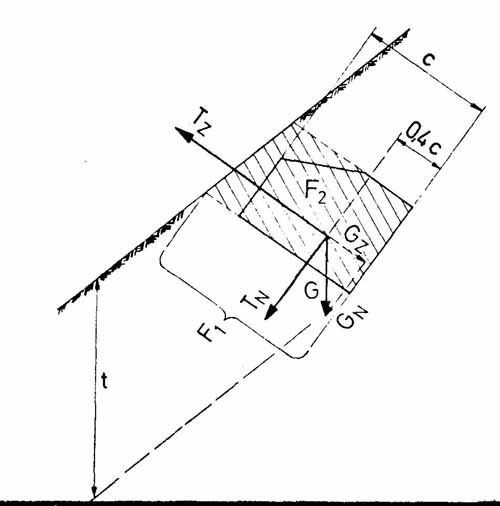
Frame fastened rigidly to the foundations. Loads exerted on the base by the frame consist of a resultant anchorage force T centred. It is applied to a point B assumed to be 2/5 of the height of the foundation base (0.4 c above the bottom of the base - cf. Fig.41). No account is taken of the resulting moment.
B represents the lower support (assumed to be a single point) of the corresponding element of the superstructure (upright or supporting pillar). It determines its load-bearing capacity. In the calculations for the upright it is assumed that the base can turn freely about its "centre" B.
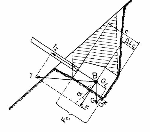
The lower sole-plate of the base fc must fulfill the following condition:
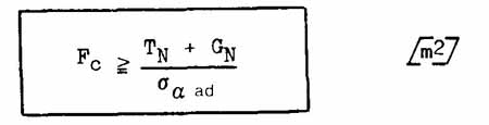
where:
TN = force perpendicular to sole-plate Fc, resulting from anchorage of the frame
GN = force perpendicular to sole-plate Fc, resulting from the weight of the foundation base + weight of earth vertically above the foundation base (hatched area in Figure 41)
ða ad = admissible compression of soil perpendicular to Fc
Jointing of frame to its foundation. The force exerted on the upper foundation by the frame consists of an eccentric resultant anchorage force T, since it is applied at the joint.
We have already stressed that jointed fastening is not generally an option with separate foundation bases underground.
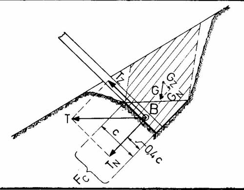
Extraction force on upper foundation base: (Size of base as a function of the soil's resistance to its extraction)
The upper base must resist extraction. The following condition must therefore be fulfilled (taking into account the weight of the structure too).
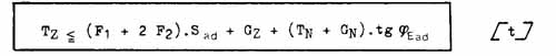
where:
Tz = force of extraction
F1 = down-slope sole-plate of the foundation base extended to the surface of the ground
F2 = side face of the foundation base expanded to the surface of the ground (hatched area in Figure 42)
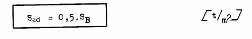
Sad =admissible shear strength of intact earth measured at the sole-plate of a sealed foundation base submitted to extraction force
SB = actual shear fracture load of intact earth measured at the soleplate of a sealed foundation base submitted to extraction force (see table below)
where:
G = weight of the foundation base + column of earth above it
TN = pressure component exerted on the sole-plate F1 of the resultant anchorage force of the frame assuming a rigid mounting (T is applied to the "centre" of the base)
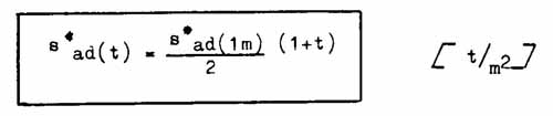
![]()
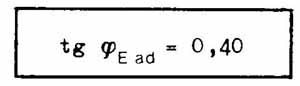
Where no special tests have been performed to determine the shear strength of Bt the following values are introduced for a maximum vertical depth of t = 1 m.:
| Type of rock or soil | SB (1m) [t/m²] |
| Compact rock | > 80 |
| Weak cracked rock | 8.0 + 80 |
| Compact earth, moraine | 2.0 + 8.0 |
| Dense, very coarse gravel | 2.0 + 4.0 |
| Dense, sandy gravel, clay | 2.0 + 2.5 |
| Loose, sandy gravel, pebbles | 1.5 + 2.0 |
Increase of SB with depth t:
| T | 1.0 m | 1.5 m | 2. 0 m | 3.0 |
| SB (t) / SB (1m) | 1.0 | 1.2 | 1.3 | 1.4 |
For other depths values are interpolated linearly. For example: for dense coarse gravel we have:
SB (1m) = 3.0 t/m²
for a maximum depth of 1.25 m. vie obtain:
SB = 1.1 . 3.0 = 3.3 t/m² and Sad = 0.5 - 3.3 = 1 .65 t/m²
e) Sunken foundations
Foundations of this type are generally prefabricated and buried on site.
Compression of soil by upper foundation base:
Rigid fastening of frame to its base
Extraction force of upper foundation base:
When the excavation does not provide a recessed emplacement to lock the prefabricated foundation in undisturbed earth, the values for shear stress are no longer valid; for the fracture due to extraction forces on the foundation does not take place in intact soil, but rather in the fill material, the cohesion of which is low. The following hypothetical calculations assume that the earth has been compacted as much as possible during filling.
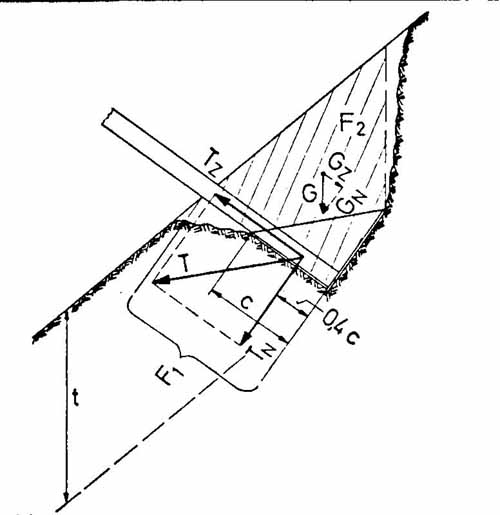
In order for the upper foundation base to resist extraction the following condition must be fulfilled (weight of the structure is taken into account).
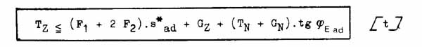
where:
Tz = force of extraction
fs = down-slope sole-plate of foundation base extended to the surface of the ground
F2 = side face of the foundation base extended to the surface of the ground (hatched area in Figure 44)
Sad = admissible shear stress in the fill material and to cover the foundation base which is subjected to a force of extraction
For a maximum foundation depth of 1 m. we have:
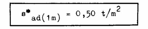
The increase of with depth t is expressed by:
where:
G = weight of foundation base + column of earth above it (hatched area in Figure 44)
TN = pressure component exerted on the sole-plate F 1 of the resultant anchorage force of the frame assuming a rigid mounting (T is applied to the "centre" of the base B)
![]()
With prefabricated foundations special attention must be paid to the risk of corrosion (a sample of soil can be analyzed by a materials laboratory to determine the presence of corrosive agents).
f) Anchoring by injection
In the case of foundations on fissured rock one should consider whether anchoring by means of injection would be cheaper than an ordinary foundation.
g) Anchoring to rock
The calculations above hold only for foundations in soil where there is no possibility of supplementary anchoring to rock. When the foundations can be anchored to rock:
- the forces of extraction can be contained by the rock so long as the anchorage is adequate,
- articulated jointing of the frame to the foundation is advantageous because the moment acting on the foundation base can also be contained by anchorage to the rock (T is applied eccentrically). Such anchorage would require too voluminous a foundation base in soil alone.
The ends of the stakes (anchoring rods) must be upset (the ends jagged). Mild steel with high elasticity must be used ( down to -30°C); hooked stakes should not be used as these open easily. In cases of great importance experts should be consulted.
The use of nets depends largely on the possibility of anchoring to rock. Such fastening must be particularly carefully executed, for the breakage of one point of anchorage can bring about the ruin of all the defence works.
Compression test
a) General comments
In order to plan a satisfactory and economical foundation, precise prior knowledge of the load-bearing qualities of the soil is necessary. For this reason the article in the guidelines dealing with general comments on the calculations for foundations requires that these qualities should be determined by standard tests.
Since the load is exerted primarily parallel to the slope, at least for the upper foundation base, tests by compression should be carried out in that direction.
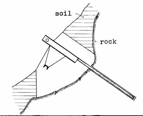
b) Method
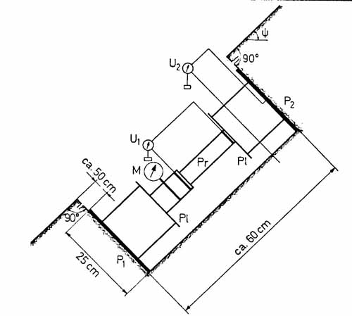
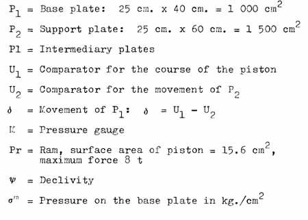
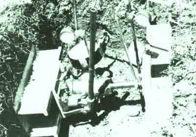
A device was made specially for the tests¹/ It consists of a lower base
plate (surface area 0.10 m² ), a hydraulic ram and an upper plate (surface area
0.15 m ). These two plates are made of sections of aluminium. A double scale
pressure gauge indicates the press re on the lower plate (kg./cm ) and on the
piston (cross section 15.6 cm , maximum pressure 8 t).
The force is transmitted to the flanges of the aluminium sections by an intermediary
plate. Movement of the lower plate is measured indirectly., For its centre is
not accessible. The course of the piston and movement of the plate are measured
by means of comparators (Huggenberger's watches) (cf. Fig.46).
¹/ Haefeli R. and Zehnder M. Fundationen Lawinenverbau 3. Bericht, Fundationskurs 1955, Versuchsanstalt fur Wasserbau und Erdbau an der ETH, 28.5.1955
c) Execution and evaluation of test
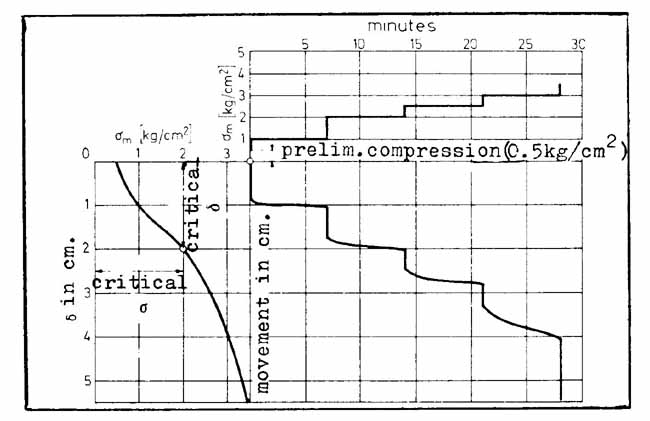
The base plate must rest entirely below the superficial soil layer of 50 cm. In order to gain easy access to the instrument, and so that it can be set up without difficulty, a trench about 1.2 m. long will be opened along the contour line. Because of its construction, the piston must move up wards. Once the instrument is set tip the soil is compressed slightly (0.25-0.5 kg./cm²) until the watches register no more variation, and the plates press in their entirety against the soil. The watches are then zeroed. Pressure is increased gradually: steps of 0.25 to 0.5 kg./cm² depending on the soil type. The pressure is read when it reaches the desired value (time 0) and again after 1, 2, 4, 8 etc. minutes until it stabilizes, keeping the pressure constant.
Pressure is then increased by one degree, and so on until critical deformation of the soil (see below) is reached. Where circumstances permit, the soil is compressed until fracture.
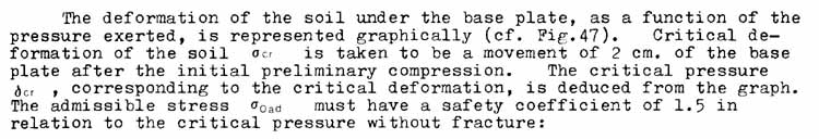
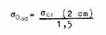
If the test is taken to fracture point at the soil we then posit:
The determinant value for a Oad should be the smaller of the two obtained above.
Percussion profile
As a complement to compression tests a percussion profile using a light penetrometer ¹/ can be useful. For each type of soil there is a correspondence between resistance to percusion and resistance to compression ²/ . In order to waste as little time as possible conducting compression tests ' one can use percussion tests to establish areas of identical resistance (or at least approximately equal). Empirically we know that two compression tests are sufficient for a given area. In certain cases stone can impede, or even preclude such tests. In this case an excavation will provide information on the soil type.
Implementation of tests
Once the structures are staked out, the site of the foundation should be tested by percussion in order to determine the points of identical resistance. When the results of the two compression tests per zone correlate with those of the percussion tests they are regarded as representative of the whole area. If not, additional tests are required.
Chapter II showed how when tension or shear stress is transformed into compression the stability of the snow cover increases. In effect, the latter is producing a fundamental increase in cohesion in the snow cover. Furthermore, compression accelerates the process of snow bonding.
¹/ Haef eli R. , Amberg G. and Von Moos A. Eine leichte Rammsonde fur geotechnische Untersuchungen. Mitteilung Nr. 21 aus der Versuchsanstalt fur Wasserbau und Erdbau an der ETH
²/ Haefeli R. and Zehnder M. Korrelationen zwischen dem spezifischen Rammwiderstand und der zulffssigen Bodenpressung in hangparalleler Richtung. Fundationen Lawinenverbau, 6. Bericht, 30-11-1957
In cases where localized shear fracture might occur in any case, neighbouring defences inhibit the lengthening of the fracture; this, in turn, reduces the volume of snow set in motion.
It is in such cases that the braking and containing potential of avalanche defences becomes paramount. The structure must, through its braking effect, eliminate the kinetic energy of the mass of moving snow (see formula on page 4, Chapter II, a term which depends on the square of the velocity).
Furthermore, we should note that it is primarily snow slides which produce these undesirable phenomena between the rows of avalanche defences. These slides occur independently of the above mentioned stresses; it is not possible to avoid these or to eliminate them; they are localized phenomena that occur because a few snow crystals become unstable. In such cases avalanche defences can only act through their braking and containing effect; for this reason particular attention must be paid to their installation.
General forces acting on defence structures:
The structures are subjected to the pressure of snow against them as well as to dynamic forces. Although the static pressure of snow serves as the base line for calculations pertaining to the structures, they must nevertheless contain possible dynamic forces to acceptable magnitudes.
The layout and size of structures is derived from the task they must fulfill, and the forces they must contain.
a) Inclination of the ground
Gradients between 30° and 50° (58 to 119 percent) usually require avalanche defence works.
Occasionally terrain of steeper or gentler gradient is included in the area of works; for example, a flattened shoulder above steep slopes.
b) Layout of defences in relation to fracture lines in the starting zone
Stabilizing structures must be placed primarily below the observed or probable highest fracture lines of snow slabs. In this way the fracture lines will be in the compression zones created by the structures; their range is two to three times Hk (Hk is the vertical height of the structure).
Despite the presence of the defence structures, secondary fractures can form below them (even in the area which was previously unstressed), so additional structures become necessary.
The area of the structures must reach down towards the valley as long as:
- the gradient remains greater than c. 30°,
- avalanches that could occur below them, and/or the snow masses that slide from among the structures, can no longer assume damaging proportions.
In the latter case decisions are reached on the basis of prevailing topographic conditions, and with a view to the type of installation being protected.
c) Layout of structures in relation to the direction in which the pressure of snow is exerted
In principle the support surfaces must be placed perpendicular to the likely direction of resultant sno W pressure. (Careful consideration must be given to narrow gulleys/valleys.)
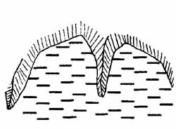
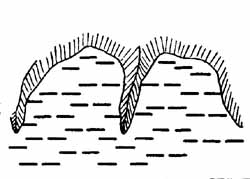
d) Particulars regarding uppermost structures
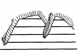
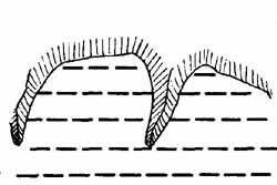
When the slope in question is delimited by a ridge with a cornice, the upper structures must be placed as close to the cornice as possible without, of course, running the risk of their being buried by it. These structures must be particularly strong due to the large deposit they will have to support, as well as because of the likely collapse of the cornice.
In a large number of cases the formation of cornices can be inhibited by wind deflecting structures which will usually have to be tested before the stabilizing structures are built.
When the slope in question is dominated by cliffs or steep rock faces, the upper defence structures must also withstand falling stones and rocks. (The superstructure should therefore be made of wood or steel covered with earth, or nets.) Damage to stabilizing structures caused by falling stones, ice or snow detached from slopes which cannot be controlled can sometimes be avoided by the use of deviating or braking structures.
e) Continuous and broken layout of defence structures
Continuous layout entails long horizontal rows of defence structures stretching over the entire area to be controlled, without any interruptions except possibly in safe areas (cf. Fig.48 a).
We must furthermore distinguish between discontinuous and broken layout.
Discontinuous rows have gaps in them (cf. Fig.48 b). in the staggered layout the structures are set out in chequer-board pattern (cf. Fig.48 C).
The three types of layout each have their advantages and drawbacks, which are set out in Table 2 below.
The choice of layout is made in relation to the protective task which must be fulfilled, bearing in mind prevailing snow conditions and the configuration of the ground.
When the protective demands are high and loose-snow slides are frequent (e.g. at high altitudes on a north-facing slope) continuous layout is strongly recommended.
Similar considerations determine the choice of types of structure.
Optimal effects are often obtained with minimum costs by combining different types of layout and, if necessary, different types of structure. Where there is doubt,an economic study should determine the choice of layout.
| Layout | Advantages |
Drawbacks |
| Continuous (cf. Fig. 48 a)) | - Fractures due to shearstress are unlikely to be transmitted
up- or downhill beyond the lines of horizontal structures - Continuous obstacle to loose-snow slides - - Considerable relief from traction forces in the snow cover - Only the ends of the rows are submitted to marginal loads (the total snow load is minimum) |
- Persistent shear stresses at the bottom or
within the snow cover, over large uninterrupted areas (and possibly traction
immediately below the structures)
- Lateral extension of any damage - Limited adaptability to broken ground and to changing snow conditions (which is of varying importance depending on the type of structure) |
| Discontinuous (cf. Fig.48 b)) | - Possibility of adapting easily to changing snow conditions
and to the ground along contours - Damage localized to particular structures - Possible lower costs by comparison to continuous layout |
- Possibility of snow slides through the gaps - Marginal loads equivalent to the length of the gaps - Fractures due to shear stress are easily transmitted beyond the structure (by comparison to continuous layout) |
| Staggered (cf. Fig. 48 c)) | Possibility of adaptation in all directions
- Elimination of all shear and tensile stresses over a whole area - Snow creep is reduced overall by comparison to other types of layout |
- Marginal loads analogous to those for an isolated structure - High costs by comparison to other types of layout - Fractures due to shear stress can be transmitted in all directions |
Examples of the lay-out of structures
Examples of the layout of structures
In practice the layout of structures is determined by the configuration of the ground. Continuous layout should be used wherever possible.
f) Rigid and slack structures
When the superstructure opposing snow creep and glide undergoes only slight elastic deformation it is defined as rigid.
On the other hand, when the superstructure can, to a certain extent, follow the movement of the snow cover, it is defined as loose or slack (e.g. net).
a) Definition of the height of the structure
The height of the structure Hk. is defined as the average vertical distance between the top of the superstructure and the ground.
The definitions for the different types of structures are given in the glossary (Chapter X).
b) Condition concerning the height of structures
The height of the structure must be at least equal to the probable extreme height of snow in the area of the structure.
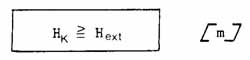
The size of the structures must fulfill this fundamental requirement which guarantees their efficacy during catastrophic conditions.
If one chooses Hk > (Hext ) , Hk replaces (Hext ) in calculations pertaining to the structure.
It should be noted that the presence of defence structures influences the settling of snow, to a greater or lesser degree depending on the type of structure, but above all on the prevailing winds.
Height of structure Hk , height Bk and effective height of superstructure Dk
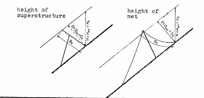
c) Definition of the height of the superstructure
Die height of the superstructure or of the net, Bk, is defined as the average distance between the upper edge and the ground, measured perpendicular to the contour line and along the surface of the superstructure.
The effective height of the superstructure or of a net, Dk , is defined analogously to the "thickness of snow'' as the average distance between the upper edge of the superstructure and the ground measured perpendicular to the slope.
The spacing between structures or rows of structures along the line of steepest gradient must fulfill the primary task of stabilizing the snow cover. Furthermore the following three conditions must be fulfilled:
- the maximum static pressure of snow against the structures must not damage them,
- slides of snow among the structures must not damage them with their dynamic forces,
- snow-slides in the area of defence work must not exceed a certain speed. In this way. kinetic energy likely to cause damage below the structures is contained to innocuous proportions.
For greater detail see the comments in the guidelines.
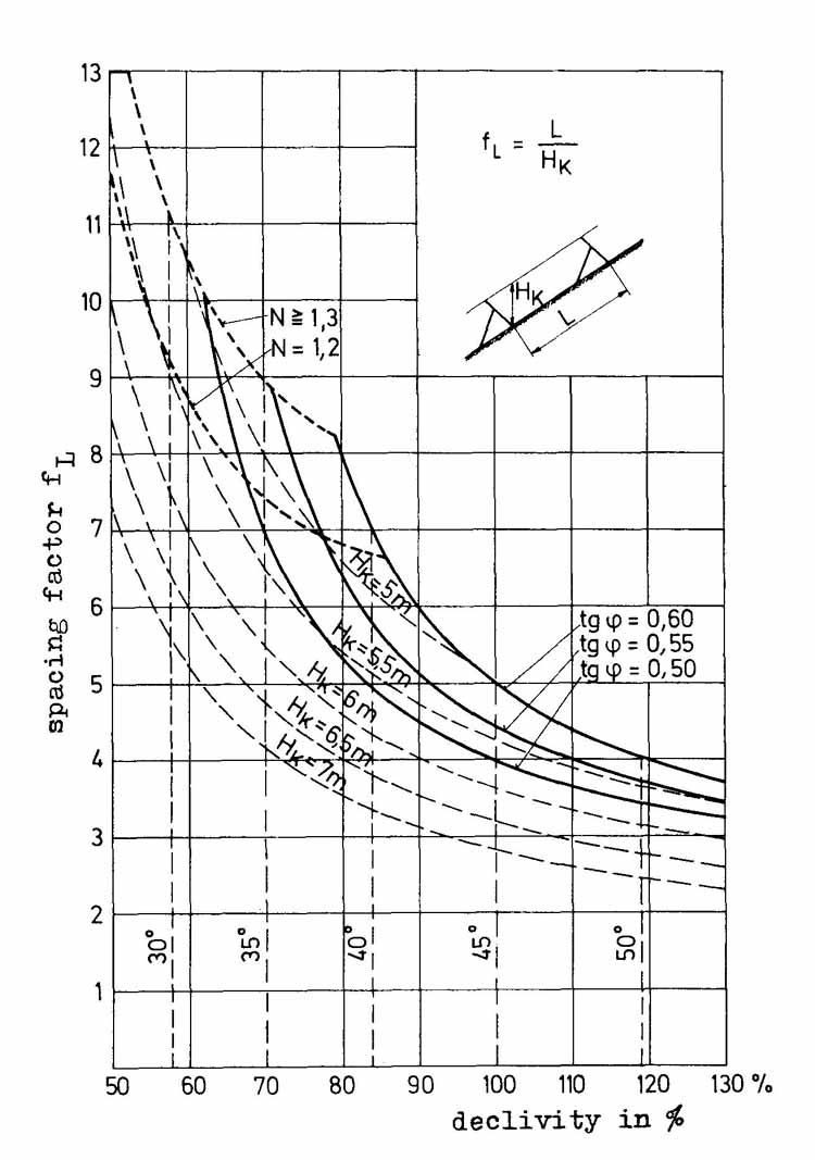
a) Spacing formula
The spacing L of structures along the line of steepest gradient is obtained by using the following formula:
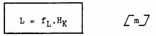
The spacing factor fL depends on the declivity and on:
- the friction angle qp between snow and ground,
- the glide factor N,
- the height of the structure Hk
Figure 50 gives f L as a function of the above parameters.
With the help of three groups of curves tg qp , N and Hk = constant, the value of fL can be determined. It should, furthermore, be noted that:
Curve tg qp = 0.55 corresponds to normal conditions. When the ground is smooth (N >= 2) or where exacting requirements demand such measures, the area between the standard curve and curve tg qp , 0.50 is used. For very rough ground (N<2) the area between the standard curve and tg qp = 0.60 is used unless safety concerns are not absolutely pre-eminent. All the proceeding is valid with the following provisos.
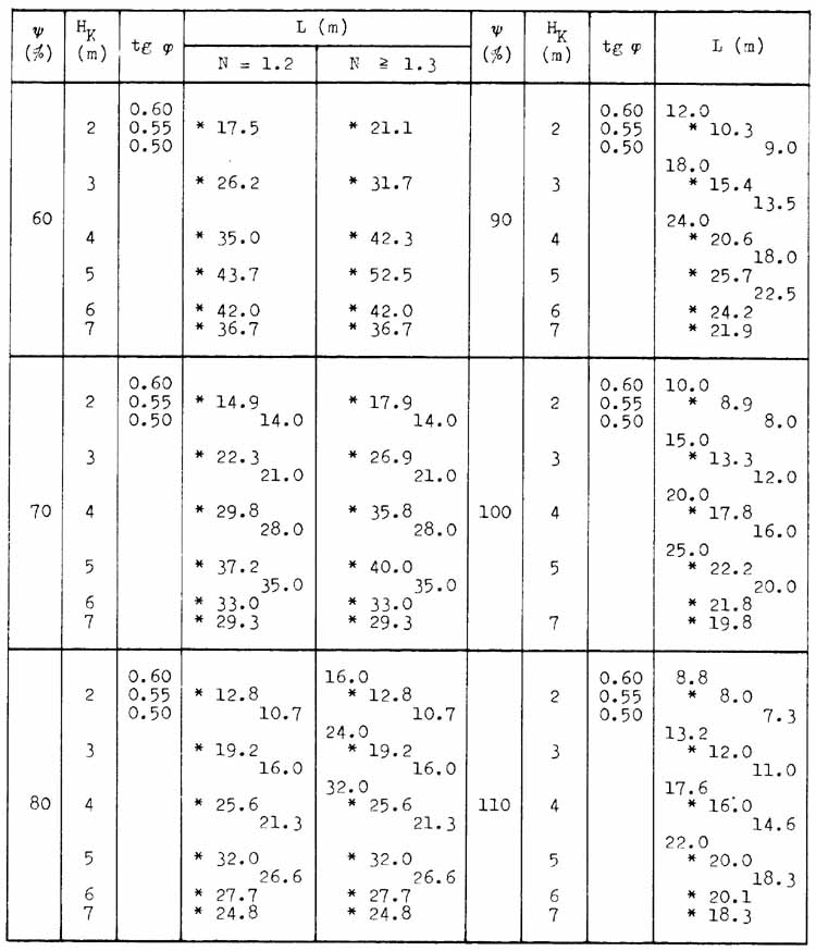
The symbol * before the above figures indicates normal values.
The curves tg qp = 0.60, 1.3 and f L = 13 represent the highest admissible values for fL
Spacing below the curve N 1.2 cannot be chosen when this value serves as a basis for calculations for the structures.
When the vertical height of the structure Hk is greater than 4.5 m, the maximum values for fL are in the curves corresponding to Hk
The tolerance included in the calculations for spacing is designed to make the snow-stabilizing structures adaptable to their protecting requirements.
When the gradient varies over the space between structures, v is the slope of a straight line joining the bases of the structures, Y is and this value is used in the calculations for L.
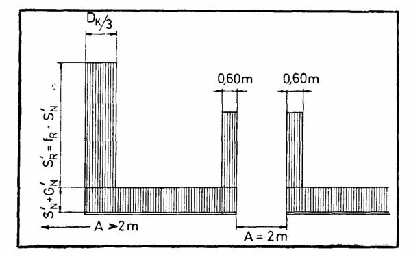
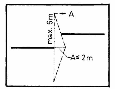
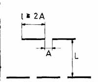
The lateral spaces A between neighbouring structures a-long the same contour line are calculated according to the following guidelines.
For a discontinuous layout the spaces must be limited to 2 m. on ground exposed to snow-slides:
A <= 2 m
The gap must be completely covered by a structure above it. (Except, of course, in the case of the uppermost row.)
If neighbouring structures are slightly staggered down the slope, the gap is determined in the manner shown in Figure 51.
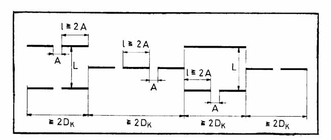
In the staggered layout of defence structures the gaps may be anywhere. Nevertheless gaps of over 2 m. along the line of gradient must be covered by a structure above them with normal spacing L (cf. Fig.52), or must satisfy the above requirements.
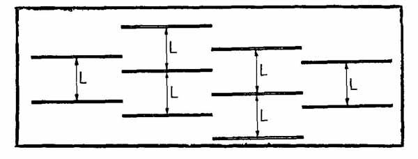
The effective length of structure 1 is the average horizontal length of the support surface.
With a discontinuous layout the effective length of the structure must be at least twice that of the gap: 1>=2A (cf Fig.53).
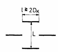
With staggered layout the length of the structure must be at least twice that of the effective height: 1 >= 2 Dk (cf. Fig. 54).
If discontinuous and staggered layouts are combined the length of the discontinuous rows along the same contour line (including the gaps) must be equivalent to at least twice the effective height (cf. Fig.55 .)
When the protective requirements are exacting we recommend that a higher value for the length of the structures is used than the minimum values below.
The pressure of snow against a snow-stabilizing structure depends on a number of localized factors:
Y = average specific gravity of snow *
H = vertical height of snow at the site of the structure
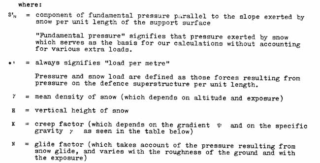
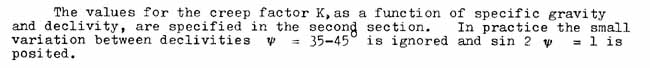
K = creep factor *, dependent on specific gravity and gradient
N = glide factor, depending on the ground, its roughness and its insolation
fc = altitude factor, which affects the specific gravity
fR = marginal factor, dependent on the gap between structures, their layout and
the glide factor
The factors designated * can be obtained through general relations; the others must be determined on site for each defence project and possibly for the siting of each structure.
a) Specific gravity of snow
For the average specific gravity of snow. such as it is in the case of extreme snow cover, a baseline value of yH = 0.270 t/m³ is used. This density corresponds to an altitude of 1 500 m. in the Swiss Alps and an exposure of WNW-N-ENE. As density varies with altitude and exposure, it too is taken into account in the altitude factor fc. and in the glide factor
N - each of which alters the pressure of snow. The increase in density due to settling is taken into consideration in the construction guidelines.
b) Height of snow on the site of the structure. The extreme height of snow H at the site of the structure is a determinant base line value for the calculation for pressure of snow.
c) Creep factor
d) Conditions of glide and glide factor
The glide factor N which represents an increase of snow pressure due to gliding of the snow cover over the ground, depends on the roughness of the ground and the exposure (insolation) of the slope. Four types of ground and two sectors of exposure are distinguished (cf. Table 4). For ground which falls between categories, N is interpolated. If the slope is greater than 45 a more extreme Scale is adopted, whereas the scale is relaxed for slopes of less than 35°.
Where the glide factor is h' h one should examine whether or not an artificial increase in roughness (terraces, rows of stakes, etc.) is preferable to building stronger structures.
Artificial increase of roughness is always essential when wooden temporary avalanche rakes are being built; for the upper foundations of such rakes are not designed to cope with large forces of traction.
e) Altitude factor
The factor of altitude f c is by no means a property inherent to the pressure of snow, but is derived once a specific gravity has been specified. It represents the increase in specific gravity with altitude, and also takes into account the increase due to the corresponding increase in the creep factor. The increase in snow pressure between 1 500 m. and 3 000 m. is approximately 2 percent per 100 m.
Altitude: 1500 1600 1700 1800 1900 2000 2100 2200 2300 m.
Altitude factor fc : 1.00 1.02 1.04 1.06 1.08 1.10 1.12 1.14 1.16
At altitudes below 1 500 m. fc = 1.00
At altitudes above 3 000 m. fc = 1.30
We have distinguished between foundations in solid rock (sealing) and those in loose soil (sealing or burying).
The studies for a defence project must include an examination of the conditions for the foundations of the structures; such a study must focus on:
- the geological makings of the ground (depth, quality and fissuration of the rock, quality of soil covering it, humidity and frost, internal movement within the soil cover (solifluction), possibly chemistry of the soil and its compatibility with the materials used in the foundations),
- the admissible soil loads (using the tests described on page 115 and those following),
Choice of type of structure:
- the loadings posed on the ground for the foundations of each type of structure; as
these vary from one type to another such a
study should be made before the choice of type of structure has been made and checked
again after,
- the type of foundation: sealed on site, or prefabricated and buried.
Table 4
Types of ground and glide factor N
| Type of soil | Glide Factor N | |
 |
 |
|
| screen with large blocks (d* > 30 em.) | ||
| ground bristling with relatively large rocks | 1.2 |
1.3 |
| Type II | ||
| pine or alder bushes at least 1 m. high | ||
| large hillocks (over 50 em. high) covered with grass or shrubs | ||
| deep-dug furrows ("cow paths") | ||
| coarse screen (d* = 10 + 30 em.) | 1.6 |
1.8 |
| Type III | ||
| short grass and cut shrubs (heather, rhododendrons, bilberry, alders, juniper and pine bushes, all at least 1 m. high) | ||
| small stones (d* =10 + 30 cm.) mixed with grass and bushes | ||
| small hillocks up to 50 em. high | ||
| covered with turf and bushes, possibly distributed over smooth turf | ||
| grass criss-crossed by small shallow furrows | 2.0 |
2.4 |
| Type IV | ||
| smooth and uniform stubble | ||
| smooth slabs of rock stratified parallel to the slope | ||
| regular pebbles mixed with earth | ||
| swampy hollows | 2.6 |
3.2 |
d* is the size of rocks: a characteristic of the roughness of the ground
The purpose of the project indirectly yields the size and layout of the structures. The problem lies in the numerical expression of the bases which the executor of the project will use, for these are a function of the material context and the protective requirements. This task has several aspects: as well as topographic considerations there are also climatic factors such as precipitation, winds, temperature and radiation. Other important considerations are the type of ground (screen, shrubs, grass etc.) and the mechanical properties of the soil (with regard to the foundations). The task is rendered even more difficult by the fact that our fundamental scientific knowledge of these matters is not complete; only direct practical experience allows these gaps in our knowledge to be overcome.
The executor of the project also has to consider the factor of costs. These are usually so high that the avalanche structures must be adapted according to their protective requirements; in other words, the cost must be balanced against what is regarded as an admissible risk.
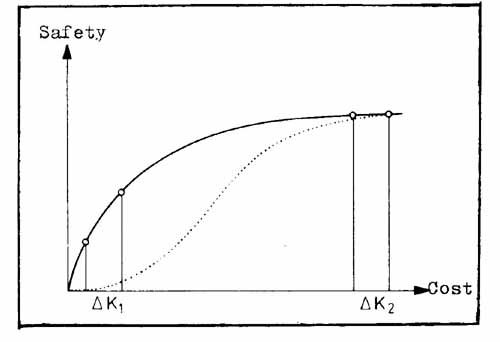
According to the guidelines it is necessary to build defences on slopes between 30 and 50 ; but it should not be excluded that exceptional conditions might demand works on slopes beyond these limits. As far as the upper limit of the area to be controlled is concerned the case is simpler: this limit is given by the highest release points of avalanches. The lower limit, though, is more problematical. We saw above (4.1.6) that the primary shear fracture dominates the moment of avalanche release, and that this fracture can propagate over a large area. For this reason, it is not sufficient to control only the upper part of the slope. Furthermore, we showed in Chapter II 1.2.2 that the destructive power of avalanches is almost independent of the size of the starting zone. For example, controlling half of a slope and thus halving the cost does not give half the safety. (This corresponds to the dotted line in Figure 56.) For this reason the whole slope must be controlled until the gradient of the slope is quite definitively below 30° . Any departure from this principle should be considered an exception and must be justified beforehand.
The fundamental requirements for the height of the structures must also take into account the possibility of avalanches in catastrophic conditions, as well as the standard methods for calculating the required dimensions. The height of the structure must at least equal the extreme height of snow that can be expected on site. The extreme height of snow must be the extreme value derived from the maximum height of snow over a long series of years. If this requirement is not fulfilled, the avalanche defences will only partially, if at all, satisfy their requirements. When the defences are covered with snow, additional tensile stresses form on their upper edge, tensions which also favour avalanche release. The braking and containing potential is then eliminated altogether. If the above requirements are to be fully satisfied, detailed knowledge of the deposition of snow over the area to be controlled must be obtained. Summary knowledge will not suffice, since the height of snow is subject to considerable variation even within very small areas. To obtain valid results 25-100 readings per hectare must be taken (by soundings or with fixed graduated poles), if possible over several winters. It was explained in Chapter II Section 1 how these values allow us to estimate the extreme heights of snow. On this subject, it is obvious that the closer the values measured are to the extreme values, the more reliable the results.
When the height of a structure Hk. is determined, most of its other dimensions should be fixed at the same time. We saw at the beginning of the chapter (para. 4.1.3) that the principal task of avalanche defences is to contain the slow downhill movement of snow. The forces which result from this and which are exerted on the structure are determinants, and allow us to calculate the requisite dimensions of the structures. All other forces, for example dynamic ones, must remain under the values obtained, and this is achieved through an appropriate layout of the defence structures.
It is the component of snow pressure parallel to the slope S'N that is the most important. This is per unit of length of the support surface free of marginal factors (cf. page 84).
where:
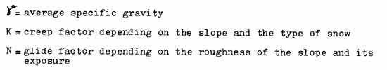
The values for K are between 0.7 and 1.05; those for N vary between 1.2 and 3.2. This last factor, in principle, takes into account the increase in pressure due to the snow cover's gliding over the ground (see table on page 83).
At the beginning of paragraph 4.3.3 we mentioned the three conditions which must simultaneously be satisfied for a correct spacing of the defence structures along the line of greatest gradient, which we recall here:
- the static pressure of snow must not damage the structures,
- snow-slides against the structures must not damage them with their dynamic force,
- snow-slides in the controlled area must not exceed a certain speed; in this way the kinetic energy capable of producing damage below the structure is contained to innocuous proportions.
If these three conditions are seen as functions of the spacing factor (fL) - in other words the ratio between the spacing between structures and their height - and of the declivity, this yields three lines on a graph. For a given case the condition or scale which yields the lowest value for spacing should be used.
To calculate the first line (cf. Fig.50) which expresses the first condition (continuous row), we assume that the snow cover between two rows of defences has lost its cohesive bond with the ground beneath it, and is sliding as a rigid slab towards the lower structure. The friction of the gliding of the snow against the ground reduces the load against the structure. This is regarded as independent of the speed, and three curves were drawn (tg qp = 0.50, 0.55, 0.60). These were calculated assuming that the pressure of the rigid snow slab which occupies the space between structures is equal to the pressure of snow S' N given in the formula above.
The "normal" curve is the one in the middle. When smooth ground with a very high glide factor is encountered and this is combined with high protective requirements, the lower curve should be used. This signifies that when a high safety factor is necessary the lower curve must be used even if the ground is rough.
On the other hand when the ground is rough and the protective requirements are not exacting the upper curve should be used.
The second and third conditions concern dynamic forces (dynamic in bold type) and speed (in faint type). Consequently a relation must be sought, represented as a function of the spacing between the structures, which will express the extent to which they can reduce speeds. For this reason, a third term equivalent to the square of the velocity has been introduced into the equation on page 4. This represents the braking effect as well as the dynamic force entailed.
Chapter II para. 1.2.2 showed the primary importance of the height of the flow of
moving snow on its speed. This height (of snow released) has been accounted for as
proportional to the extreme height of snow. This proportion was increased when the
declivity of the slope was gentle (to 0.25 instead of 0.20), which in turn allowed the
inclusion of an increased shear strength when there is an extra load. In order that the
structures are not exposed to abnormal forces when there are snow-slides, it is essential
that these should not exert pressures above the pressure of snow yielded by the formula on
page 134. The identity of these values yields the group of curves which correspond 1 to
the second condition. By introducing a constant speed (10 m./sec.-1 ) in the
relation between spacing of structures and speed# a quantitative value for the third
condition is obtained.
We should stress once again that the braking potential of avalanche defences depends
primarily on the angle of deviation (cf. Fig.57). The smaller the angle the lower the
braking effect. The formation of ramps (hatched area of Figure 57) is feared, with good
cause; this cannot be avoided altogether. It is extremely undesirable, though, that snow
should deposit in this manner from the beginning of winter onwards. This tendency is
thwarted by ensuring that adequate gaps are left between the bars of the superstructure,
but it should not be forgotten that over-large gaps reduce the braking effect. In areas
where loose-snow slides are common, primary attention must be devoted to this problem.
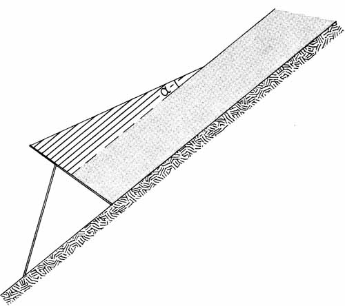
Before reaching the decision to deploy snow-stabilizing structures, all the other possibilities must be reviewed - structures described in other chapters: deviating, braking, containing, direct protection, deflection, etc. - as well as the possibility of using various combinations of these. This not only allows for considerable savings on the costs, but also gives effective protection most quickly.
Let us remember that such planning must take into consideration not only climatic, topographic, geological and botanical considerations, all mentioned above, but also the possibilities of transportation. In particular the plans must include detailed research on the local history of avalanches, and use the results of direct observations of the height of snow in the area in question, as well as the circumstances in which avalanches are released.
When dealing with a large area the choice of the most important slopes requiring, control is crucial, and must be made in relation to the goals of the project. Furthermore we should remember that the structures cannot be restricted to the starting zone - either observed or potential - for the structures themselves need protecting. This means that safety precautions must be taken both above them and at their sides. Avalanche defences must therefore be placed at the top of the slope first, even if the area of release is lower down.
Current thought holds that slopes between 30 0 and 50 0 require avalanche defences (paragraph 4.3.1). It is important that not only these gradients are borne in mind, for careful consideration must also be given to the extension of works downhill, towards the valley. Avalanche defences which do not extend downhill sufficiently can reduce the efficacy of the whole system, and it will be no compensation to maintain later that one was trying to economize, or that one had underestimated the extent of secondary starting zones.
When permanent protection is required, the choice of permanent or temporary structure will depend on the possibility, and the chance of success, of reforestation. Permanent structures are primarily limited to areas above the treeline. One should also foresee their use when the forest-to-be might require more time than the maximum effective duration of temporary structures. This holds above all for the upper limits of the forest rather than for marginal positions within it. In the latter case, a permanent frame with an impregnated wooden superstructure of limited life expectancy is sufficient.
The staking-out of structures on the ground must be carried out following the guidelines mentioned above. In these the spacing of structures along the line of greatest gradient is given as a function of the height of the structures H . Since the heights of the superstructures are in practice fixed at from 2- 5 m. with variations of 0. 5 m., complementary calculations must be carried out which will allow one to pass directly from DK to L
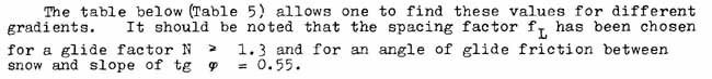
To draw up a cost estimate, the most expensive factor consists of the length of the structures. This can be determiend by staking out the structures on the ground if the area to be controlled is small, but not if it is large. In this case, calculations allow one to make an accurate estimate of the length of the structures required. A relatively simple formula has been established.
where:
| qp (0) |
D (m) |
H.K (m) |
L (m) |
| 2.0 | 2.31 |
25.6 |
|
| 2.5 | 2.88 |
32.0 |
|
| 3.0 | 3.46 |
38.4 |
|
| 30 | 3.5 | 4.04 |
44.8 |
| 4.0 | 4.62 |
51.3 |
|
| 4.5 | 5.20 |
50.1 |
|
| 5.0 | 5.77 |
47.9 |
|
| 2.0 | 2.45 |
21.9 |
|
| 2.5 | 3.05 |
27.1 |
|
| 3.0 | 3.66 |
32.6 |
|
| 35 | 3.5 | 4.27 |
38.0 |
| 4.0 | 4.88 |
40.0 |
|
| 4.5 | 5.49 |
35.7 |
|
| 5.0 | 6.11 |
33.6 |
|
| 2.0 | 2.61 |
15.1 |
|
| 2.5 | 3.26 |
18.9 |
|
| 3.0 | 3.92 |
22.7 |
|
| 40 | 3.5 | 4.57 |
26.5 |
| 4.0 | 5.22 |
30.3 |
|
| 4.5 | 5.87 |
26.4 |
|
| 5.0 | 6.53 |
24.8 |
|
| 2.0 | 2.83 |
12.6 |
|
| 2.5 | 3.54 |
15.8 |
|
| 3.0 | 4.24 |
18.9 |
|
| 45 | 3.5 | 4.95 |
22.0 |
| 4.0 | 5.66 |
22.9 |
|
| 4.5 | 6.36 |
21.3 |
|
| 5.0 | 7.07 |
19.8 |
|
| 2.0 | 3.11 |
11.7 |
|
| 2.5 | 3.89 |
14.6 |
|
| 3.0 | 4.67 |
17.5 |
|
| 50 | 3.5 | 5.44 |
20.4 |
| 4.0 | 6.22 |
18.7 |
|
| 4.5 | 7.00 |
17.2 |
|
| 5.0 | 7.78 |
15.6 |
The latter, assuming snow bridges 4 m high, gaps of 2 m. and structures of varying lengths consisting of bridges with crossbeams with an effective span of 2 m., is equivalent to:
0.68 for 4 - 2 - 4 2 - 4 m
0.84 for 10 - 2 - 10 2 - 10 m
0.92 for 22 - 2 - 22 2 - 22 m
1.00 for continuous layout
Example of use of this formula:
F = 74 000 m² , average declivity = 40° (84%)
(Hext ) (average extreme heights of snow) = 350 cm.
The graph (Fig.50) allows us to find fL which here is 5.8 for the middle curve (tg qp = 0.55)
(Hext ) allows us to determine D. D = (Hext ) cos 40° where D = 350 . 0.766 = 268 cm.
The closest dimension above this is D = 3.0 m.
We can thus write:
![]()
The layout factor must be chosen by the project planner. If continuous layout is chosen we obtain:
4253 x 1.00 = 4253 m¹
If discontinuous layout 4 - 2 - 4 - 2 - 4 is used:
4253 x 0.68 = 2892 m¹
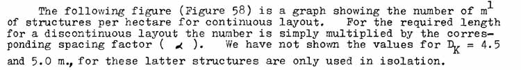
We should further note that the curve DK 4.0 m. does not obey the empirical rule which holds that the spacing of the structures is proportional to the effective height of their superstructure, beginning from 47° If curves had been drawn for DK = 4.5 m. and DK. = 5.0 m. the divergence would have been even more marked. This is due to the conditions regarding dynamic forces, set out above, which also have to be satisfied.
The price of the crossbeams of the structure in a continuous layout constitutes approximately 60 percent of the total costs. There is therefor little room for economies here since discontinuous layout offers a lower margin of safety and the foundations are identical. What is far more important than the degree of discontinuity is following the guidelines rigorously in the constructions. It is often surprising to discover in areas where defences have already been built, that the length of structure per hectare is quite small.
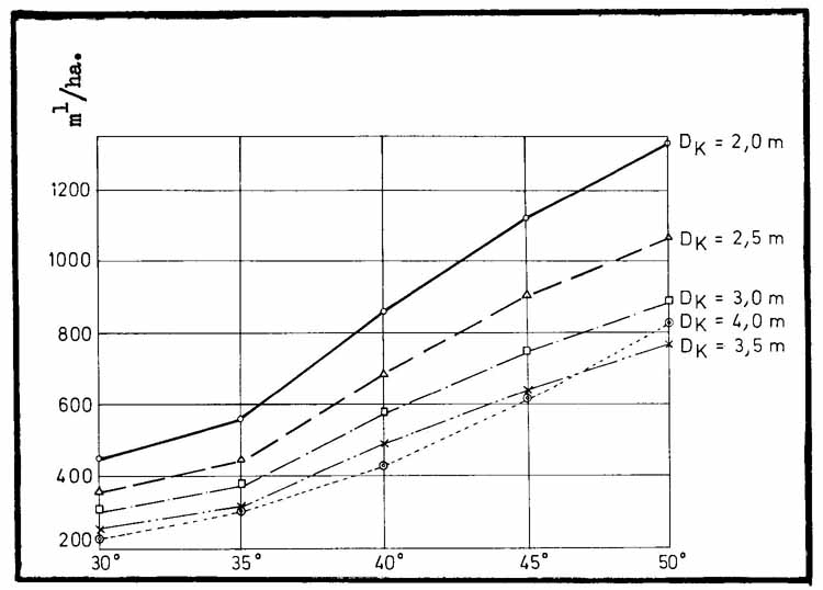
Almost unlimited technical progress has blunted man's critical faculties considerably. We trust technology blindly and without reflection; large sectors of the population imagine that avalanche defences in a starting zone offer complete safety.
This complete safety is an illusion. An area cannot be controlled completely in the course of one season. This is materially impossible for many reasons: the shortage of manpower, delays in delivery of materials and cost of the work; furthermore even where manpower is available it is hardly possible for numerous teens of men to work at the same time on a steep slope without running high risks of an accident.
For this reason it is necessary to stagger the work into several stages. This allows for substantial savings, providing one caters for the release of small avalanches below the lowest stage of the work. Furthermore, observations during the winter will show where the most dangerous areas are, and where the work should proceed with maximum urgency.
The aim of snow stabilizing structures is to prevent the release of avalanches, or at least to reduce the movements of the snow to a harmless magnitude - they cannot be prevented completely. Complete safety means that one has eliminated all risk entirely, even in the case of catastrophic conditions.
Snow is not an homogeneous material; its properties vary both overtime and space. Its behaviour is subject to external influences of enormous variety. This is the pre-eminent cause of difficulties when one seeks to place this variety of factors into an equation and to take effective precautions to avoid damage
Composite snow stabilizing structures have been used on a large scale since 1950. The advantages of this system with respect to the antiquated massive designs no longer need demonstrating. If one wishes to judge their efficacy one would conclude that in the main they have fulfilled the protective demands made on them. We do not even dare consider the damage that would have occurred in the Alps without them. It must be admitted that occasionally avalanches have started in controlled areas, and that here and there the strength of structures has been insufficient. Places in which defences have hitherto performed satisfactorily have not yet proven their ability to withstand catastrophic conditions.
It would be unfair to doubt the efficacy of snow stabilizing structures because here and there a few areas (or parts thereof) have been defective. We must always expect such localized setbacks, but these must never discourage us, but rather drive us on to discover the cause of failure and correct it.
This is exactly what men have been doing since the beginning of such work in the second half of the nineteenth century. In the 1930s, basic research began, and since then there has been a happy collaboration between research and practical experience. The Swiss guidelines, first published in 1955, have been revised four times up to 1968, each time becoming more stringent. This proves that the hopes initially placed in snow stabilization structures were not entirely borne out, but it also proves that lessons were learned each time. Finally, we can claim that the latest defences built - in so far as the guidelines were followed closely - afford a much greater degree of safety than the structures of yesterday.
The science of snow has made considerable progress, but there remains much to do and research is unlikely to run out of work. The duty of the expert is to apply reasonably, to a defined objective, the experience gained and the most modern knowledge on the subject. As we will see, this is far from easy.
The variety of factors which characterize each site is even more marked in winter than at other times of the year, for in addition to altitude, exposure, the configuration of the ground, topography, changes in gradient and the soil cover, we also have snow, the deposition of which is locally modified by the wind. We must not be surprised that with such superabundance of variables we must make do with guidelines; in other words instructions often leaving much latitude in their utilization. Vie must therefore follow the guidelines and try and draw precise conclusions from the given information: the most important and the most difficult task facing the expert. The degree of safety obtained through snow stabilization structures is primarily a function of the possibility that the executor of the project has to know the avalanche starting zone% to define them, and to interpret winter aspects of the terrain.
The identification of starting zones is not always possible in winter. Although it is usually possible to find part of the fracture lines, avalanches usually occur in bad weather, and so new, falls of snow combined with wind obliterate the fracture so well that it is virtually unfindable. Thus work must be based on reliable observation combined with a good ability to interpret one's knowledge of winter conditions. The distressing belief in "inspiration from the gods" which one still finds amongst foresters here and there must be banished forever.
The choice of spacing between structures along the line of steepest gradient is the expert's most weighty decision. This spacing effectively determines the density of defensive structures. As the density increases so does the efficacy of the structures; the guidelines leave a considerable margin of choice up to the planner as this allows one to establish the correct spacing in relation to the degree of safety required from the defences.
A high degree of safety is necessary when an inhabited centre is being protected; in such cases minimum spacing is chosen. The latitude allowed regarding choice of spacing must never be used for economic ends. It is therefore out of the question to choose maximum spacing in order to obtain a financially valid controlled area: such reasoning certainly gives a theoretically satisfying solution as far as the first of the three conditions goes, but also a much lower margin of safety for avalanche release within the controlled area (second and third conditions). When dealing with a small project, financial considerations are hardly relevant; but nevertheless a forestry engineer who is used to having to find the most economical solutions to problems might be scared off by a large-scale project. When the guidelines cannot be fulfilled in order to give works providing the necessary degree of safety, it is better to renounce building snow-stabilizing structures altogether. It is particularly difficult to determine the height of the structures which must be equivalent to the extreme height of snow. When the defences are covered with snow, they lose part of their influence and also risk being overloaded. They can then no longer hold new snowfalls, and surface avalanches can start and trigger off large avalanches down-slope from the structures. In certain cases, overloading the structures can cause them to collapse. Meteorological data allows a rough estimate of the requisite height of the structures by giving the average extreme heights of snow for an area. This information is not sufficient to determine the extreme heights of snow that one could measure on the spot, but then again it is almost impossible to actually take such measurements as extreme heights of snow might only occur once in thirty years.
The only solution is to observe the area to be controlled uninterruptedly oneself over several winters in order to then estimate the extreme heights of snow by analogy and by using the guidelines. In order to make these observations, graduated poles placed at representative points over the area are used. Photogrammetry can also be used to estimate these heights. Experiments on topographic maps scale 1:2000 have shown that for an area of 8 ha. a degree of accuracy equivalent to the nearest 20 cm. can be obtained. When one has to control a difficult area with a maximum degree of safety, this latter method must be used despite its rather high cost.
The wind complicates the determination of the requisite height of the structure, for it causes important variations in the deposition of snow. Hollows in the ground are often filled up from the very first snowfall, whereas humps and ridges are often bare right into spring. It is essential for the planner to know the direction and speed of the prevailing winds.
When dangerous areas carry so much snow that the highest normal defence structures can no longer emerge above it (height of snow greater than 5.50 m.), the use of snowstabilizing structures becomes problematical. When the lie of the ground allows it, once can try to influence the deposition of snow by channelling the wind with the help of deflecting structures described in Chapter VII. This solution allows one to increase the margin of safety with little additional cost in a fair number of cases.
Avalanche defences are regarded as necessary on slopes between 30 and 50° (paragraph 4.3.1). Below a gradient of 30° nothing is usually done. Above 45-50° the slope usually discharges itself continuously during snowfalls in the form of small, harmless, slides of snow. A problem occurs at the base of such steep slopes, for the structures there must be of sufficient size to deal with these supplementary snow slides. These can in fact fill up the avalanche defences prematurely, thereby reducing their efficacy considerably. It is also possible that these snow slides from the steep slope above might occasionally assume volumes that cannot be contained by the upper defences, thereby filling up the defences below them. It is extremely difficult to make a quantitative estimate of such occurrences, but an error here can be fatal for the efficacy of the whole complex of defences.
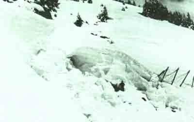
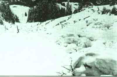
These difficulties are increased still further when stonefall is common, or when the steep slope is crossed by tracts of gentler gradient. If the mass of snow deposited on such tracts is released, the problem is insoluble.
The strength of the superstructure of the avalanche defences is not sufficient to ensure their efficacy. This also depends on the anchorage conditions to the ground. The foundations of the upright and the supporting pillar must be adapted to the soil resistance. ',,hen this consists of solid rock there is no problem. When dealing with well drained screen and moraine the case is fairly simple. On the other hand, when one finds rock such as marls which are more or less clayey or schists that are -,lore or less altered one can immediately foresee that the foundations will present problems. If the soil is weak, the upper and lower foundation bases will usually have to be joined by a tie-bar. In difficult cases, the cost of the foundations can amount to 50 percent of the total. Whilst on this subject, we should remember the usefulness of compression tests and percussion profiles, which are insufficiently used by experts (see pp.115-118). Isolated structures built on inadequate foundations on weak soil in certain areas have collapsed as soon as the load of snow was slightly high.
We must also mention another thorny problem. Usually only the upper areas of avalanche starting zones are visible. Once the avalanche defences have been built, new starting zones can appear below them. These zones, which can be called "secondary", could not have been detected beforehand. In such circumstances, the works already completed will only reduce the frequency of avalanches, shorten their trajectory and reduce their volume, but the danger remains - albeit reduced. ',,hen one fixes the lower limit of the extent of the defence works, this should be borne in mind.
Within all large areas of avalanche defences one finds well and less well built parts, particularly when the ground poses problems. It is usually possible to reinforce, at a later date, the areas which have been revealed to be too -weak through regular observations. This finally allows one to obtain the degree of safety desired. On the financial side, this will usually entail the need to obtain supplementary credit to finish off the defences.
Finally we must insist, for financial reasons, that the planner should have a detailed knowledge of the yea. Usually one hectare of avalanche defences on a regular slope of 45° requires 600 to 800 m. of structures. Because of their high cost, these must be placed in the most economical manner possible, and this can only be accomplished if one has an adequate knowledge of the ground. Also important is a good organization of the works, and provision of the appropriate materials. On the other hand, one must never skimp on the quality of materials or the density of structures required in each case. It is not here that one should attempt to economize.
The above leads us to conclude that it is not possible to express in figures or in percentages the risk that remains once such defences have been completed. Suffice it to say that these structures ensure excellent and almost complete safety during the course of normal winters. But the works are carried out with a view to catastrophic conditions, and in such cases protection is never completely guaranteed. This means in practice:
- that during critical periods the population living below an area of defences must realize that danger remains, and must therefore behave accordingly and take the appropriate precautions (which in some cases can mean evacuation),
- that the installation of avalanche defences does not mean that areas classed as dangerous (red) in the initial plans of areas for construction can now be declassified for free building.
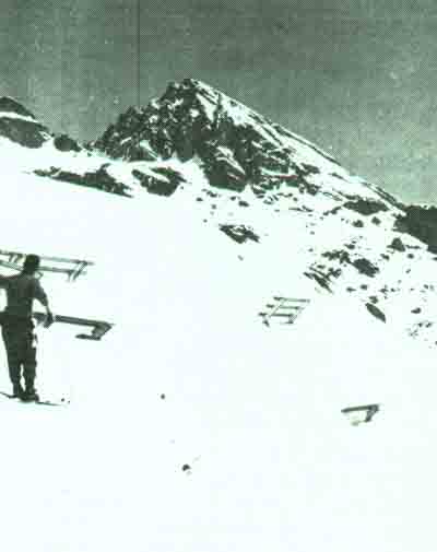
Overloaded defences during spring
47 - Correct height of avalanche defences. A snow drift has covered two of the structures. A wind baffle placed there subsequently eliminated the abnormal snow cover over these three bridges.
48 and 49 - Avalanche defences too low. The bridge withstood the load. Note the large amount of snow creep below the superstructure.
Rather they can be regarded as areas of reduced avalanche danger (blue zones), - where certain buildings can be erected on condition that reinforcements or at least some restrictions are included.
Building avalanche defences is not sufficient; they must be looked after and checked regularly, bolts or clamps must be tightened, anchorage points and foundations much be checked, damaged sections and uprooted foundations, whether due to local overloading or stone falls during summer, must be changed.
In order to run effective checks, a map of the defences must be at hand, which gives the exact position of the structures on an appropriate scale (1:500 or 1:1000; photogranmetry can also be used).
This map is also necessary to mark observations made during winter, such as small avalanches within the controlled area, crevasses due to snow creep, structures covered by snow drifts.
The map will also include all other relevant information, such as areas for reforestation, areas -where small berms or banked terraces are to be built in order to increase the roughness of the ground (or rather to decrease the glide factor N).
As a complement to this map, a cadastral survey of all the structures must be drawn up. The best way to do this is in tabular form with the number of the structure, its length, type, its foundations, the spacing, the gradient of the slope, the glide factor and any damage reported for it.
Equally a photographic enlargement can be given to each observer. The photograph is taken from the observation point and on it is superimposed a piece of tracing paper. In this way the observer merely has to write what he sees, such as the thickness of snow at critical points (both on the network of graduated poles, and by counting the number of crossbeams above the snow cover).
It must not be forgotten that the degree of safety sought during construction must be maintained over decades, i.e. permanently, for this reason these checks must be made regularly. Places damaged must be repaired without delay, and the same applies to any faults which are thereby revealed. Negligence in this upkeep leads to a reduction in safety and the possibility of unpleasant consequences. Permanent upkeep of the structures is a fundamental requirement for their efficacy.
An area of defences that has suffered damage is more dangerous than one without any defences. In effect the population is lulled into a false sense of security.
General maintenance works and particularly repair of damage require considerable means. Usually such upkeep increases as the structures get older, and consequently all this must be taken into account at the planning stage. Generally, maintenance is much easier to carry out, and costs considerably lower, if access to the structures with spare materials is easy. For this reason transportation by helicopter or by cableways should be replaced by tracks all over the area wherever possible.
Winter view of an area of avalanche defences (discontinuous layout). Winter observations revealed certain weaknesses in this complex, and it was subsequently reinforced and adapted to conform to the latest guidelines at the same time.
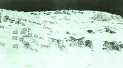
Summer view of this adaptation. Recent analysis by the Weissfluhjoch Institute showed that the results were still not satisfactory even though some parts were in some ways 'lover equipped% This is generally the case with old controlled areas completed before precise guidelines were adopted.
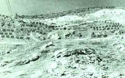
Example of an avalanche-defence-area map Scale: 1:500
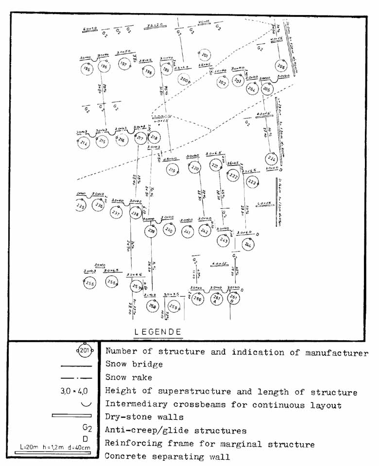
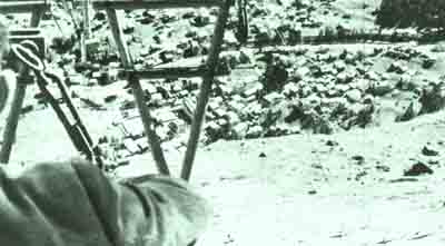
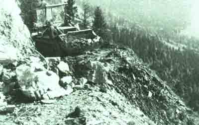
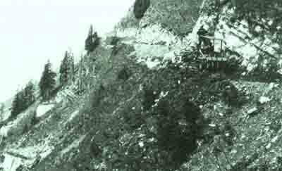
53 and 54 - After 35 years a road has been built. Work is made more difficult by the presence of reforested areas below, which also need maintenance.
The Weissfluhjoch guidelines advise the following:
- Lateral extent of snow stabilizing works:
Even from the summit of the starting zone, the layout of the structures must extend far enough width-wise to cover uniformly the area in question, and reach natural spurs on which to rest (cf. Fig.60).
In cases where either the configuration of the ground or prohibitive costs do not allow the sides of the end most structures to rest in such natural supports, the unprotected structures at the ends of the rows must be staggered inwards as they go down the slope so that lower structures will not be damaged by avalanches running down the edge of the controlled area. In order to prevent neighbouring, avalanches from encroaching on the structures, in so far as this is possible, additional structures can be added in the middle of space L at the ends of the rows. These should be of minimum length 1 of approximately 2 D y Separating walls approximately H Y/2 high, and placed along the line of greatest gradient, will stop full-depth avalanches from encroaching and will also considerably reduce marginal loads as seen in Article 31. In order to protect the supporting pillar these separating walls should be extended parallel to the edge of the structure as far as the foundation of the supporting pillar (Fig.61).
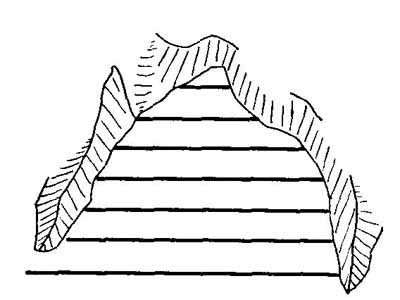
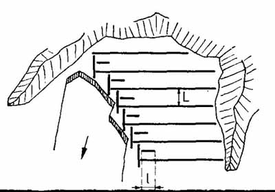
The avalanche defences placed at the edge of the area have to withstand an additional marginal static load which can be as much as two to five times that of the force exerted parallel to the slope. Added to this there is also the possibility of dynamic forces produced by avalanches released near to the structure. For this reason entire areas between two natural lateral supports (ridges/outcrops) should be controlled if at all possible. The above precautions are not always possible, and nor are they entirely sufficient even if Article II (inward staggering arrangement) of the guidelines is applied. Additional precautions must be taken.
The simplest is to add an extra -1rwie set into the edge of the superstructure. This precaution may not suffice if factor N is high. In this case separating walls must be built of height Hk/2 and arranged along the line of steepest gradient; alternatively the frame and the supporting pillar can be sunk into a wall of the same height. These walls prevent full-depth avalanches from encroaching on the controlled area, and also reduce marginal loads by a considerable factor.
Equally well suited are small supplementary bridges (Dk= 1 m.) which will relieve the marginal structures; or for that matter one can also construct terraces (of earth or rock).
In areas where separating walls are not necessary, avalanches can be prevented from spreading from the non-controlled area through the use of supplementary defense structures (see preceding page).
When a controlled area is threatened at the sides by avalanches, a lateral deviating structure can also be used. It must not be forgotten that such deviating structures can create new problems because they alter the deposition of winddriven snow.
If the marginal structures are at risk from dynamic forces, we recommend that the structures should be reinforced by an additional element of the frame placed in the middle of the superstructure by way of a complementary precaution.
In cases where the lowest row of structures is close to the protected objects (such as a road or a railway line) we recommend that continuous structures with a superstructure higher than strictly necessary should be built, and that these should be covered with netting with diagonal mesh. This ensures that any snow - slides will be braked and halted more effectively.
When a complex of net defences has been built we nevertheless recommend that the lowest row should consist of continuous bridges or rakes. These will contain any snow-slides which come through the nets.
It is difficult to give exact figures in these inflationary times. A recent study of the cost of steel defences for a given slope of known glide factor and length follows by way of example (see Fig.62).
Since the price of foundations depends on their volume, and as transport costs vary from area to area, only the costs of the frames and the superstructures of the fences have been taken into consideration.
The graph shows the clear correlation between the price per meter and the height Dk and moreover a sharp increase in cost for a high Dk
The purchase price for a bridge of Dk = 5 m. is 75 percent more than that for a bridge 1), 4 m. Furthermore, in the example we have chosen, one would need 700 m. Of DK 5 m. bridges and 600 m. of Dk 4 m. bridges
(the empirical rule "the larger the structure the greater their spacing" does not hold above Dk = 4 m. - see Figure 58). Consequently, practical solutions aiming to reduce the height of snow by means of deflecting structures must be sought, or alternatively, the Dk = 4 m. structures can be placed on small walls to make up the missing height.
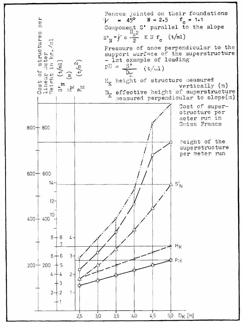
Structures of limited duration.
Discussions of such structures must be the same is if they were permanent ones, but less durable such as wood can used in their construction.
Wherever mountain -forest cannot he reconstituted without the use of avalanche defences, and where such reforestation will not take more than 30 to 40 ;ears before trees replace the defences, the structures should be of a temporary nature.
Wood a has clear advantage over others since it has high resistance to compression and -to traction the direction of its fibres. Furthermore, it is easily adapted on site to the conditions of the ground by using very simple tools: nails, screws and steel plates. Round timbers can be used which are easily replaced if defective. Wood is relatively light in relation to its strength, and lastly, wood used in prefabricated foundations allows one to dispense with concrete.
One must not forget that wood is subject to rotting, especially if it is unprotected or in contact with the ground. Furthermore, wood is a natural material and can therefore have defects. Pieces which are likely to be used must therefore be selected carefully, and must be chosen for their resistance to rotting and for their high quantity of heartwood.
Furthermore, life expectancy of structures can be increased by impregnating them either totally or partially (by osmosis, completed by chemical treatment of the sections in contact with the ground; products should be chosen which are as non-toxic as possible but which diffuse easily and yet will not be washed off by bad weather).
Tricks of construction such as protecting pieces laid horizontally by a sheet of aluminium or of tin plate, using split timbers (in half or in quarters) with the rounded side turned towards the ground for the crossbeams, not using wood of greater diameter than necessary nor woods rich in medullary rays etc. are all recommended.
On the technical level it is desirable that wooden avalanche defences do not come into contact with the ground as this prolongs their life; on the other hand this increases their cost considerably.
Steel anchorages should be used for the upper foundations and either prefabricated concrete or a flat stone should be used under the supporting pillar.
Vie recommend that only continuous layout of fences of Hk > 3m. should be used, as this allows one to economise on the reinforced structures at the ends of the rows.
The same criteria for maintenance checks discussed for permanent structures apply here. During the summer checks, the wood should also be tested for rotting by sounding with a hammer (the tone of rotten wood is different from that of healthy wood).
Snow rakes have always been preferred to bridges in the construction of avalanche defences for the following reasons:
- anchoring the lower longitudinal beam is easier than the two classical points of anchorage for a bridge,
- the crossbeams of a rake placed vertically are less prone to rotting,
- reforestation is impeded to a lesser degree by the vertical beans of a rake than a bridge
On the basis of constructions already completed the Weissfluhjoch Institute has, with the special care of the forestry engineer In der Gand, perfected this type of structure, and we believe that builders of avalanche defences can put this model to good use. This rake was designed according to the guidelines of the Institute in Davos, taking into account the statics of wooden constructions and the need for a design which affords maximum protection from wood-rot (see Figures 63 and 64).
It should be noted that the inclination of the superstructure has been reduced by comparison to the wooden rakes of former times which were more inclined downhill, producing the disadvantages:
- the greater the downhill inclination of the superstructure the greater the pressure of snow
- greater danger that the structure will form a ramp
- as snow flows through the rake it tends to shear the superstructure which in turn increase, the traction on the foundations,
- the greater the inclination of the superstructure the more wood one requires, for the beams have to be larger and longer.
These drawbacks greatly out weigh the slender advantage that exists only for the upper foundation, which is submitted to a weaker force of traction. For these reasons we recommend that the superstructure is not inclined any more than is suggested in the guidelines.
The free length of beam is chosen in order to obtain balanced moments of flexion; this reduces the requisite diameter of the logs and thus indirectly the sources of wood-rot.
The pressure of snow exerted on the superstructure is transmitted to the ground through the lower longitudinal beam which doubles as the upper foundation. The upper longitudinal beam transmits pressure to the supporting pillars in the same way as in older structures.
Hitherto the lower longitudinal beam has usually been anchored on to a small terrace and fixed by using stakes, sunk at least one meter into the ground, alternately above and below the beam, and then it is all held together with cable (see Fig.64). This solution, even when carried out carefully, constitutes the weakest link in the system. The guidelines suggest that the roughness of the soil be increased in areas where snow creep/glide is particularly significant and might tear out the lower longitudinal beam (for example by building small terraces or sinking stakes). The guidelines advise against building such structures on over-steep slopes or where the snow cover is too thick since the foundations may not be able to withstand the traction. Furthermore, there are no means for calculating the properties of anchorages by stakes.
The solution put forward here also holds for permanent structures. The lower longitudinal beam plus the lower part of the crossbeams are buried at a minimum depth of one meter. In such cases, traction along the plane of the superstructure must not exceed the resistance of the soil. The guidelines give the method for calculations for the upper foundation. One must bear in mind that in practice it is often difficult to bury the lower beam completely in the ground on site. By way of precaution, we must assume an admissible shear stress for the fill material of 0.5 t/m² at a depth of one meter.
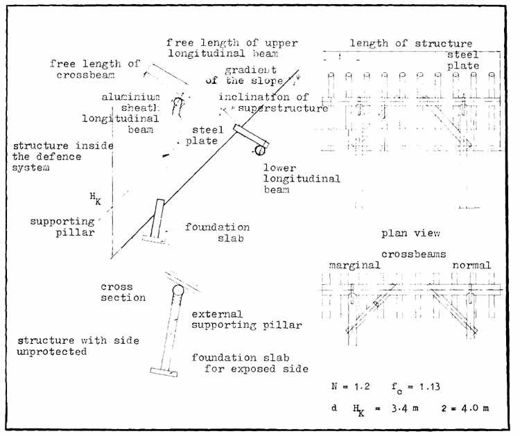
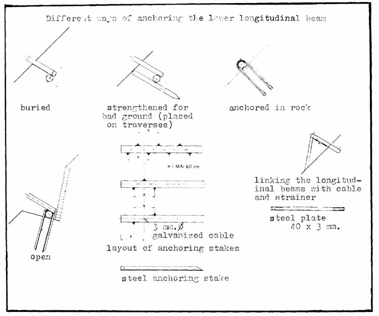
The following graphs (Figure 65) have been drawn according to the guidelines, and show the admissible anchoring forces for half a 4 m. structure (exposed side RW and inside the defence system IW) for different heights (Hk) of rakes ranging from 1.5 to 4.5 m. The graph on the left holds when there is no snow creep (N 1.2), the one on the right holds for an average snow creep (N 1.8) on ground which has been reforested and had small berms made on it. The maximum height K) of the rakes is given by the point of intersection of the curve for admissible force (Tz Zul and that for maximum force (Tz max.).
The results are given below.
Hk admissible in metres for SFISAR-type rakes of 4 m. length, anchored but not buried, buried, anchored and buried (0.8 m. deep) with N 1.2/fc 1.13, and N 1.8/fc 1.02, on the uncovered side RW, inside a defence scheme IW. It has been assumed that the stake anchorage could withstand a traction force of 1 t. for half the structure (A, B and C, see Figure 65).
In summary one can say that:
- a buried lower longitudinal beam gives better anchorage and indirectly allows larger rakes to be built. For example, a rake 4.2 m. high inside a defence system requires the following sized round timbers for N 1. 8: beams 16 em. lower longitudinal beam 20 em. supporting pillars 19 em. f or a length of 4m. upper longitudinal beam 24 em. (this section, which is the heaviest, weighs 100 kg.);
- the choice of anchorage system (buried or not) must be based on calculations which give the maximum traction force exerted locally and the admissible forces for the anchorage;
- when anchorage with stakes is chosen (buried or otherwise) the admissible stress must be judged by experience.
The system using a buried beam also offers the following advantages:
- it stops the batter above collapsing, and also stops landslides due to the cutting necessary in continuous layouts;
- it reduces infiltration which can cause dangerous packing under the longitudinal beam;
- it increases the structure's resistance to tangential pressures;
- it eliminates the upkeep on the berm of the upper foundations.
Naturally one will give the necessary dimensions to the upper foundation, not only to resist traction, but also as a function of the soil's resistance to pressure. When the latter is not sufficient the pressure exerted by the lower foundation must be reduced by driving a series of stakes as deep as possible parallel to the superstructure below the lower longitudinal beams (see Fig.64).
If rock breaks the surface, anchoring is done by means of U-shaped mild steel rods (the same as those used in reinforced concrete) the ends of which should be upset and jagged and sealed into the rock; better still is Ushaped steel cable as this allows the holes for anchoring to be made less exactly, thus simplifying the job.
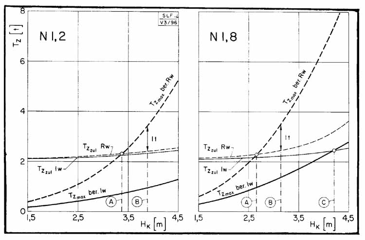
|
N |
Beam not buried anchored with stakes | Beam buried Not anchored Anchored with stakes | ||||
| Exposed side | Inside a defence system | |||||
|
RW
|
IW | RW |
IW |
MY | IW | |
| A |
B |
C | ||||
|
1.2 |
2.4
|
4.0 |
3.3 |
>= 4.5
|
3.8 | >= 4.5 |
|
1.8 |
1.8
|
2.6 |
2.6 |
4.2 |
3.1 | >= 4.5 |
The upper foundation longitudinal beam supports the beams on the one hand, and on the other transmits the pressure from the superstructure to the two supporting pillars. Its dimensions must be determined with the same calculations used for the beams (balanced flexion movements). The diameter of the supporting pillars and their resistance to buckling must be calculated in relation to their length and to the load they have to transmit, following the instructions in the guidelines. The surface of the supporting pillar on which the longitudinal beam rests must be sawn in a semi-circle on site to avoid uneven distribution of the loads. This must be done as precisely as possible. If the radius of the semicircle is too short the load might split the supporting pillar (wedge effect).
Before putting the beams in place, the upper longitudinal beam must be covered with a metal sheet (aluminium or tin plate) which protects it from rain and melt water.
The foundations of the supporting pillars consist of slabs of reinforced concrete with a protruding pin (made of concrete reinforcing rod) and are adapted to the admissible pressure on the soil in the direction in which it is exerted. The supporting pillar is simply rested on the slab and placed on the pin after an appropriate hole has been made in the middle of its base. For the same reasons mentioned above, the lower foundations can be banked up. In this case the part of the structure in the earth (whether it is the lower longitudinal beam or the base of the supporting pillars) must be particularly well protected from rotting.
(We will not discuss this subject which is beyond the scope of this manual; there are several procedures which we can mention - those used in industrial impregnation, for railway sleepers or for electricity poles small scale, done by osmosis and, in the area of contact with the ground, with a complementary chemical treatment.)
The joints between the pieces forming the superstructure and the frame are nailed (round nails with cylindrical heads). Nailed joints are better than other types as they cost less and because, usually, the pieces of wood do not need holes drilling in them in advance.
On the basis of results obtained at the federal laboratory of materials testing in Dubendorf (Switzerland) there is no need to reduce the admissible loads on a structure consisting of round timbers nailed into squared timbers two-thirds of the size; nor are there any grounds for rejecting a structure of round timbers nailed to other round timbers as foreseen in norm DIN 1052. All the avalanche structures of round timbers nailed to each other proved to be strong enough in the tests. The following table gives the admissible shear strain for each nail:
Admissible shear strain per nail |
||
Type of nail Ø/ length (in mm.) |
According to norm SIA 164 |
Estimated on the basis of load testing (EMPA ¹/) |
| 8.5/300, 275 | 199 kg. | 250 kg. |
| 7.5/260, 245 | 164 | 205 |
| 7.0/230 | 147 | 185 |
| 6.5/215, 200, 180 | 131 | 165 |
| 5.5 160, 150 | 100 | 125 |
| 5.0/150, 140, 130 | 85 | 105 |
¹/Federal Laboratory for Materials Testing and Research Institute, CH-8600 Dubendorf
The underlined figures can be used if the following instructions are followed (see also Fig.66):
a) The type of nail must be chosen not only for its strength but also for its length so that its point will penetrate to a minimum depth 8 x its diameter, according to SIA norms. For round timbers this is a little optimistic so it is better to follow the following rule: independent of the type of nail this must be of a length equal to the diameter of the wood that will be nailed plus 10 cm.
b) The gap between nails must conform to the intervals shown in Figure 66 in order to prevent the wood splitting.
c) The nails must be sunk perpendicular to the plane of the superstructure. The heads must not be sunk but must simply touch the surface of the wood. This allows the directions for the structure to be followed more accurately and reduces the chances of the wood splitting.
d) To reduce rusting and to increase their resistance to extraction, the nails used must be phosphated.
In cases where the nailed joints between superstructure and frame are not strong enough, these can be reinforced by a binding with cables resting on steel plates which will prevent them from cutting into the wood.
Finally the upper longitudinal beam and the supporting pillars are joined by means of steel plates, one placed above and one below the pillar see photos 55 to 64).
Snow creep and glide is known to all experts; and numerous solutions have already been devised to stop this phenomenon, which is particularly manifested on even, grassy slopes exposed to the sun, between 1 200 m. and 2 500 m. above sea level (gradient 28-50°), and especially where the snow is wet through to the ground. From a distance, these areas can be recognized by the sickle-shaped crevasses which form in the snow cover, and also by avalanche-like snow-slides. They can easily be documented with photographs taken after a snow fall on non-frozen ground (see photos 65 and 66). The pressure exerted against all obstacles by snow creep and glide is very great and damage to avalanche defences, plantations and occasionally other objects can be considerable: clumps of trees and entire structures can be removed with the top strata of soil. Plantations can be damaged or even torn out (see photos 67 and 68).
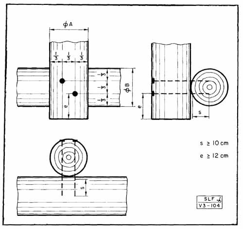
In the struggle against this pressure, theoretically increasing the roughness of the soil - reducing the glide factor N - is sufficient.
In practice, the roughness of smooth slopes above 28° will have to be increased. Furthermore, the structures designed to combat snow creep and glide will have to be distributed over the entire area, in such a way that neither the soil nor the snow above will be placed under shear stresses greater than the admissible values.
In principle there are three ways of creating structures which combat snow creep and glide: a) small banks or berms analogous to cow-trails on sloping pastures,
b) networks of stakes two-thirds buried in the ground and protruding 30-50 em.,
c) miniature bridges, rakes, or tripods (HK = 1-1.5 m.) or a combination of berms and stakes.
6.1 Small terraces are 30-50 em. wide, their horizontal spacing is a function of the gradient of the slope.
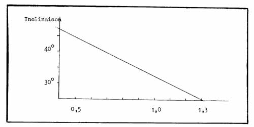
They can be built either continuously or discontinuously. Spring is the best time of the year to build them, for they can then be packed and sufficient consolidation will occur in the period up to winter. They also offer the advantages of preparing the ground for plantations and of being cheap (in addition they help to control weeds).
They must not be made when the soil is not consolidated. They should be sloped slightly towards the nearest depression in order to improve water run-off (see photos 69, 70 and 71).
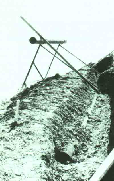
Assembly of a snow rake made of round impregnated timbers:
55 The lower longitudinal beam is in place. A metal former facilitates the placement of the lower foundations.

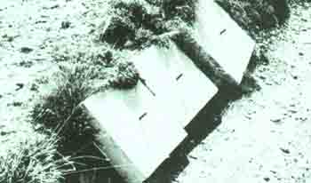
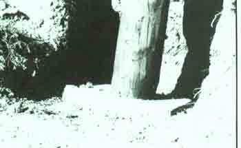
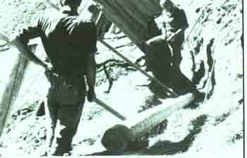
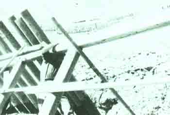
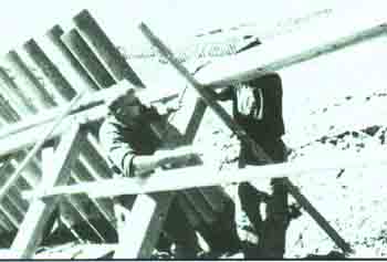
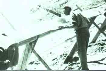
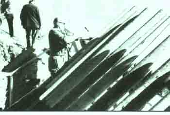
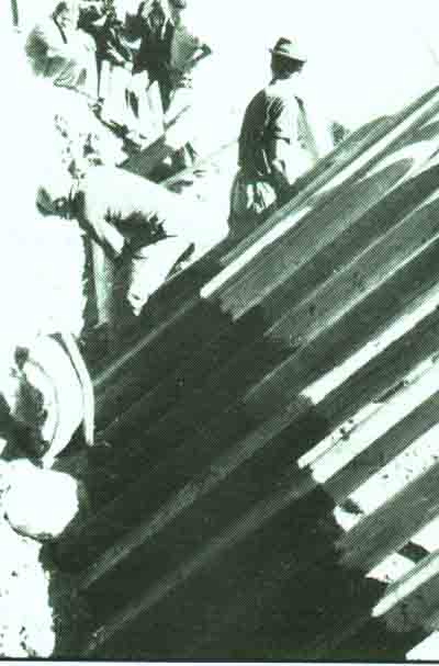
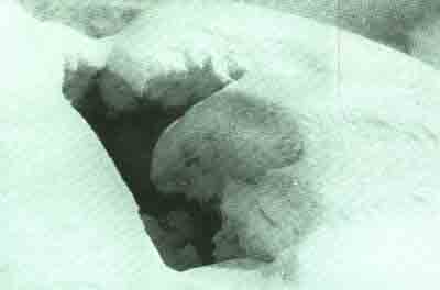
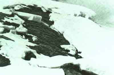
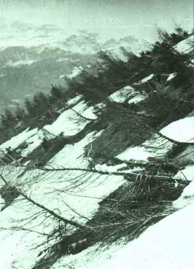
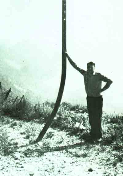
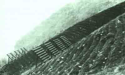
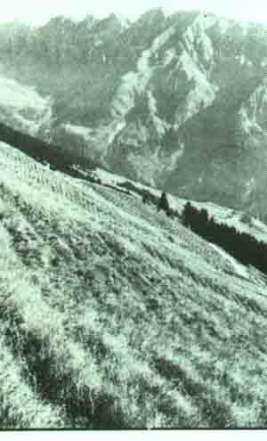
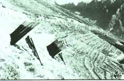
69, 70 and 71 - Practical examples of small berms or terraces
- their batter stops them being built with sufficient density when the slope is steep,
- the pressure of snow can flatten the embarked part, and furthermore, undesirable areas of tension in the snow cover are formed along the edge of the berms (areas of potential release of snow-slides),
- the cost of the work is disproportionate in relation to the meagre advantages,
- they cannot be used in soils subject to landslides. It is not without good reason that this system which was used at the dawn of avalanche defence work has now been abandoned.
6.3 Stakes (a third of the length of which, and never less than 30 to 50 em., must protrude above the ground) can be round (minimum diameter 10 em.) or split timbers (minimum Ø c. 16 em.) or quartered timbers (minimum Ø 20 cm.). The gap between them must be chosen in relation to the gradient of the slope and the height of snow: approximately 2 500 stakes per hectare for a 30° slope and 1.5 m. of snow, up to 12 000 stakes per hectare for slopes of 45-50° and 3 m. of snow.
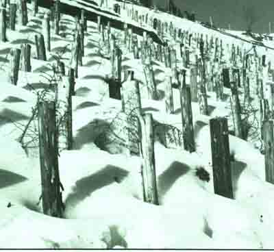
This system has the advantage of fixing 3 the top layer of soil at the same time, but requires between 20 and 150 m³ of stakes per hectare. There is the drawback that it cannot be used if the soil is not deep.
When the soil cover is thin, stakes and terraces cannot be used. It is only in such cases that other anti-creep and glide structures should be used (rakes etc.). Their effectiveness is not as great, and can at best increase the roughness of the ground in a normal-sized defence area or where there is a high frequency of wet-snow slides. Their upper foundations must be anchored, they must not be more than 3 m. long and their spacing on the slope must be less than 10 m.
These small rakes can be made of wood or metal. Their cost is relatively high.
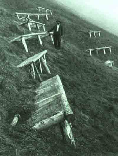
Anti-creep and glide structures
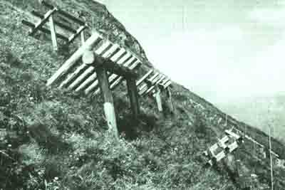
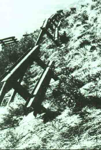
Depending on their size, the cost of structures made of wood is between one third and one quarter of that of metal ones (steel). It is difficult to give comparative figures as the cost of labour varies from country to country, and because each area presents difficulties which cannot be compared.
As far as narrow berms are concerned, these depend above all on the type of ground encountered, which determines the rate of work. All that can be said is that networks of stakes cost more than berms. As for small rakes, these cost relatively more than normal avalanche defences because their construction is not carried out en-masse.
Let us remember that, from the forestry point of view, it is possible to combine clearing in an area of woodland with the construction of a nearby defence scheme, provided that the impregnation plant is not too distant.
![]()
![]()
![]()