![]()
![]()
![]()
Since this review concerns the potential of irrigation canals for fisheries and aquaculture, the following section outlines the general features of irrigation systems. Those most commonly found in developing countries are generally in the form of unlined and lined open canals.
The design of these systems follows a common pattern, and many similarities are to be found between irrigation systems in widely separated parts of the world. For this reason, the following description of the characteristics of irrigation schemes is a general one, and the reader should refer to Jones (1981), Mather (1983) and Michael (1978) for more information on the general principles of irrigation engineering.
Surface irrigation systems usually consist of a network of open canals, which may or may not be lined to prevent seepage and/or erosion. It is usual in developing countries for them to be unlined since this type of canal is easy to build, with low capital costs, and can be easily maintained by unskilled labourers.
Canals are designed to carry a specified discharge without erosion and traditionally have a trapezoidal shape. The basic elements of open canals are shown in Figures 1 and 2.
Canal banks - These generally have a slope of 1:1.5. However this ratio is usually increased to 1:2 with sandy soils and decreased to 1:1 with clay soils.
Canal gradient - This depends on the lie of the land but normally the slope would be approximately 0.1%. Slopes of less than 0.05% often lead to siltation in the canal. Water velocities in canals with steeper gradients can be controlled by drop structures or by building up the canal bed. Michael (1978) suggests the following velocities for various soil textures:
| Soil Texture | Max. recommended velocity |
|---|---|
| cm/s | |
| Bare canals | |
| Sand and silt | 45 |
| Loam, sandy loam, silt loam | 60 |
| Clay loam | 65 |
| Clay | 70 |
| Vegetated Canals | |
| Poor vegetation | 90 |
| Fair vegetation | 120 |
| Good vegetation | 150 |
Velocities greater than these should be avoided if erosion is to be prevented.
Canal Cross Sections - It is thought that the most efficient cross section for open canals is a semi circle, since with this form of construction the wetted perimeter is at a minimum and the hydraulic radius is at a maximum (hydraulic radius is cross sectional area divided by the wetted perimeter). A high hydraulic radius is recommended for canals carrying larger flows. However, semi-circular construction is only possible in small sized lined canals or enclosed pipework. Consequently, most unlined canals have a trapezoidal cross section (Figures 1, 2) to accommodate high flows.
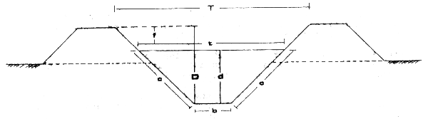
Figure 1 Elements of an open channel
Key:
T - top width of the channel
t - width of surface when water is at depth d
D - depth of channel after free board is added
d - depth of flow in channel
c - wetted sides of channel
f - free board
l - angle between sloping sides of the horizontal
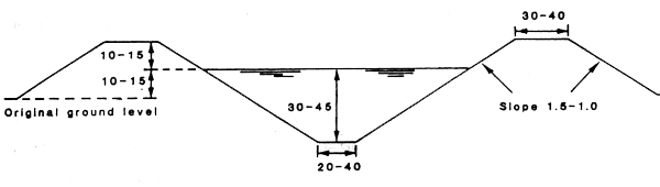
Figure 2 Typical cross-section of an unlined field canal
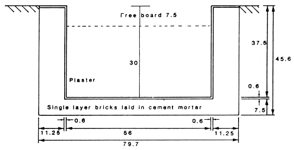
Figure 3 Cross-section of a brick-lined channel
In lined canals the cross-section is often rectangular. These canals occupy less of the agricultural land, but are also is more costly to construct (Figure 3).
Unlined canals, whilst attractive because of their low construction costs, have a number of disadvantages which may have serious consequences for crop production, and which also have implications for fish production. These problems are examined in section 3.
These canals are normally lined with concrete, brick or stone. Other types of lining more recently used include polythene films, bitumous mixtures, soil cement, chemical sealants and impervious earth materials (Michael, 1978). These have a limited life, however, and are susceptible to damage by livestock and excessive water velocity. Concrete linings, although costly, have a longer lifespan with minimal repair and maintenance costs.
Canal banks - The slope of the banks can be greater in lined canals than in earth canals, but should not exceed a slope of 1:1, unless the concrete is hand placed and the canal over 60 cm in depth. Brick, flat clay tile and stone lined canals are recommended for water courses where the velocity exceeds 30 cm/s. A typical cross-section is shown in Figure 3.
In certain areas of the world there are extensive aquifers; Bangladesh is a prime example, and much of the irrigated area is supplied by numerous tube wells which tap the underground water resources. These wells each supply only small areas, a few hectares at most. Water is pumped from the well on demand, and is distributed to the fields by a series of tertiary and quaternary canals. In such systems there is no potential for fish culture in the irrigation canals.
There are several advantages in using pressurised underground systems compared to that of open canals. Pipes take less land out of cultivation and do not interfere with farm operations. They are essentially leakproof and have a long life, with little maintenance and are not easily damaged. Water is applied to the crops by sprinkler or trickle systems and little labour is involved. Water use is very efficient, although costly. The main design elements of an underground pipeline system are shown in Figure 4. The increasing use of pressurised systems, especially in developed countries and for high value crops, may considerably reduce the fisheries potential of irrigation systems (particularly at the local level).
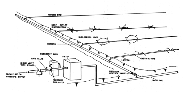
Figure 4 The main design elements of an underground pipeline system
This section describes the typical layout and design characteristics of an unlined–canal water distribution system. It is based on existing projects in Indonesia (courtesy Silsoe College, Bedford, UK) and the Farahaane Irrigation Rehabilitation Scheme in Somalia (courtesy of Sir M McDonald and Partners Ltd Cambridge, UK).
Figure 5 shows the layout of a standard scheme (this example being in Indonesia), and Figure 6 an irrigation system in Sudan, which is a variation on this theme.
Generally, primary canals distribute water from the source to the secondary canals which in turn supply the tertiary canals. The water then passes to the quaternary or field canals and so to the crops. The dimensional and flow characteristics for each category of canal are given in Table 3. The data is drawn from several examples of irrigation systems, and is therefore generalised.
| Canal type Comments | Bed width* (m) | Bank Slope | Depth (m) | Flow 1/s |
|---|---|---|---|---|
| Primary | 5–6 | 1.5–2 | 1–1.2 | 800 |
| Secondary | 2–3 | 1.5–2 | 0.5–0.7 | 20–400 |
| Tertiary | 0.01–0.1 | 1.0 | 0.1 | 0–20 |
| Quaternary | " | " | " | " |
* Note: this refers to the bed width of the channel, not thewidth at its surface
Flow rates are based on a flow requirement of 2 litres per second per hactare for a rice crop.
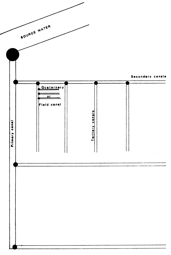
Figure 5 Layout of an irrigation scheme (e.g. Indonesia)
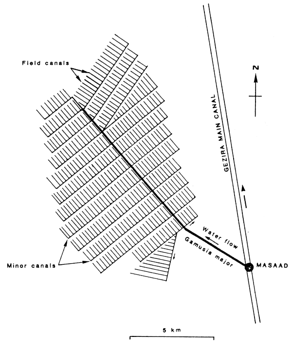
Figure 6 The Gezira Irrigation Scheme, Sudan (gravity flow through unlined earth canals)
With irrigation systems being standardised to such a high degree, it is possible to estimate, quite accurately, the length of each category of canal in a given system. It is obviously important to know this if estimates, at anything but the individual level, of the aquaculture or fisheries potential of irrigation systems are to be made. Based on a standard 5 000 hectare project (a common size), for each unit of 1 000 hectares the average canal lengths in each category are as follows;
| Primaries | 2.5km |
| Secondaries | 10km |
| Tertiaries | 100km |
| Quaternaries | 400km |
Given these formulae, and assuming a standard width for each category of canal, it is possible to make a very rough estimate of the water area of an irrigation system of a given size.
![]()
![]()
![]()