![]()
![]()
![]()
![]()
The equipment for the harvesting system, described in the following pages, consists of chain-saws for felling, a construction crane for logging and a wood processor for processing, which includes delimbing and bucking the trees and their piling.
3.1. Construction crane
The construction crane FAUN RTF 40-3 was used for logging during this study because of its weight, lifting capacity, high manoeuvrability and suitable dimensions (see Photo 2). This construction crane is also suitable for the worker because it meets ergonomic principles and requirements. Its design and safety features assure convenient and safe operation, which are prerequisites for the operator's sustained performance.

Photo 2. The FAUN RTF 40-3 is a 3 axle all-terrain crane with a telescoping boom.
The FAUN RTF 40-3 is a 3 axle all-terrain crane with a telescoping boom. Due to its width, turning radius and high manoeuvrability this crane can certainly be used, during dry seasons or when the ground is frozen, on all forest roads meeting the usual standards (see Photo 3). Problems concerning the road-bearing capacities might occur during wet seasons, but as mentioned above, this is not a specific problem for the crane vehicle.

Photo 3. Usual forest road standard (formation width of 6 m, carriageway width of 4 m).
Once the driver has reached the area where the crane is to be set up, he must manoeuvre the vehicle so that it stands at a right angle to the road center line; this will provide maximum machine stability during the supported operation. The front of the vehicle should be pointing opposite to the work area since over-front lifting might damage the driver's cab if the lifted load begins to swing.
When the vehicle is in the correct position, the outriggers must be extended so as to support the operation, thereby providing maximum lifting capacities. The outriggers must be set up on firm level ground; square-sawn timber between outriggers and ground provides a level surface and helps to distribute the pressure evenly so that ground damage or shearing failure might not occur (see Photo 4).
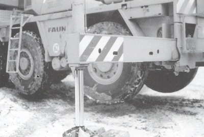
Photo 4. Extended outriggers for supported operation.
If the carriageway width is not adequate (distance between 1st and 3rd axle = 4.15m) the outriggers next to the driver's cab must be set up on forest ground which might have to be prepared so as to be level (about 1 square meter for each outrigger).
After joining the hoisting equipment to the hook-block of the stabilized machine the telescoping boom will be extended (maximum boom length 30 m and maximum radius of action 28 m (see Figure 1).

Figure 1. Radius from center of rotation and hook height above ground.
Specifications given by the manufacturer of the all-terrain crane FAUN RTF 40-3 with optional all-wheel drive:
width of vehicle |
2.50 m |
width of vehicle with extended outriggers |
6.28 m |
length of vehicle |
8.45 m |
length of vehicle with lowered boom |
11.21 m |
height of vehicle with lowered boom |
3.35 m |
distance between 1st and 2nd axle |
1.70 m |
distance between 1st and 3rd axle |
4.15 m |
Axle loads with complete counterweight (metric tons): |
|||||||||||||||||||||||
1st axle |
10.65 t |
3rd axle |
11.50 t | ||||||||||||||||||||
2nd axle |
10.65 t |
Gross vehicle weight |
32.80 t | ||||||||||||||||||||
Max. speed |
70 km/h |
Gradability |
40 % | ||||||||||||||||||||
|
|||||||||||||||||||||||
Hoisting rope (diam-eter) |
16 mm |
Ultimate strength |
170 kN | ||||||||||||||||||||
Max. rope pulling power |
45 kN |
Hoisting rope (length) 160 m |
|||||||||||||||||||||
Main hoisting line speed (4th layer) |
0 - 60 m/min | ||||||||||||||||||||||
High speed |
0 - 120 m/min | ||||||||||||||||||||||
Auxiliary hoisting line speed
Hook-block Hoisting equipment |
0 - 80 m/min 75 kg ~ 13 kg | ||||||||||||||||||||||
Different steering possibilities assure high manoeuvrability and permit different turning radii of the vehicle (see Figure 2).

Figure 2. Steering possibilities (schematic); turning radius for vehicle (A) 10.6 m; (B) 8.6 m; (C) cannot be turned because all wheels point in one direction.
Some examples of lifting capacities of the telescoping boom (with complete counterweight of 6.6 t, slewing range of 360_, with outriggers), stated by the manufacturer, are given in Table 3. This shows that the lifting capacity depends on the telescoping condition, which is determined by the immediate boom length, so in case a log or tree exceeds the permissible weight it can first be pulled with "raised head" and then with decreasing distance the whole tree can be lifted since lifting capacity is therefore increased.
Table 3. Lifting capacities (85%) for the FAUN RTF 40-3 in metric tons.
Radius |
Boom lengths | |||||
(m) |
9.30 m |
16.20 m |
23.10 m |
28.60 m |
30.00 m | |
7 |
16.70 |
16.30 |
15.15 |
11.90 |
10.85 | |
14 |
6.50 |
6.30 |
6.80 |
6.80 | ||
21 |
2.80 |
3.10 |
3.20 | |||
26 |
2.00 |
2.00 | ||||
28 |
1.70 | |||||
telesc. 1 |
0 |
50 |
100 |
100 |
100 | |
telesc. 2 |
0 |
50 |
100 |
100 |
100 | |
telesc. 3 |
0 |
0 |
0 |
80 |
100 | |
telescoping conditions (%) | ||||||
"Lifting capacities of 85%" means that these lifting capacities do not exceed 85% of the tipping load,
but it must be mentioned that wind and dynamic interferences decrease the lifting capacities.
The hoisting equipment used consisted of two 6 m long ropes with log tongs of different sizes on the one end and were connected with a loop on the other end to a 6 m long synthetic sling which was joined to the hook-block. The hook-block hangs on a rope about 5 m from the top of the boom, thereby increasing the effective radius of action to approximate-ly 45 m, depending on the slope of the terrain.
If the trees are felled to point toward the location where the construction crane is set up, the distance which the crane can cover consists of the extraction distance plus the length of the felled trees, so in our first case, study area A, where the sites for setting up the crane were on the forest road, the extraction distance amounted to 70 m. Provided the terrain is accessible as in study area B, the crane can be situated a whole boom length from the road so that the extraction distance increases to about 90 - 100 m (see Photo 5).

Photo 5. The construction crane can be set up at the felling site, provided the terrain is accessible and the ground is frozen.
The extraction distance mentioned above is limited by the weight of the hook-block and hoisting equipment, which cannot be manoeuvred easily by one assistant alone, and, considering labour costs, a second worker employed to pull out this equipment cannot be recommended in a country like Austria where labour costs are high.
The alternative to using a lighter hook-block is limited because the block needs a minimum weight so that the rope can be extracted. The only way was to reduce the weight of the hoisting equipment by the use of a synthetic sling and two ropes instead of iron chains which were used when the first attempts at logging with construction cranes took place, but not dealt with in this study. It should be noted that a heavier than necessary hook-block should not be used. This would diminish the optimum load weight since lifting capacity = actual load + hook-block + hoisting equipment.
A significant advantage of the FAUN RTF 40-3 and other comparable types of construction cranes is the fully automatic overload protection device. In case the tension exceeds the permissible boom tension, all functions will be shut off automatically so that the safety hazard is reduced to a minimum. The boom has to be retracted thereafter or aligned once more in order to decrease the boom stress.
3.2. Wood processor
During previous operations of a construction crane which was used in combination with a wood processor, the crane processor STEYR KP 40 was mounted on a wheeled excavator.
The STEYR KP 40 is a one-grip crane processor which can be mounted on different carrier vehicles such as trucks, skidders or excavators. The manufacturer recommends the use of a carrier vehicle with 88- to 100-kW engine power (see Figure 3).
agricultural
tractor forwarder
skidder excavator

Figure 3. One-grip crane processor mounted on different carrier vehicles.
In contrast to smaller processors for thinning operations the STEYR KP 40 is a machine designed for continuous operation and can be used in combination with other machines. The optimal range of use which provides acceptable production is between 14 and 35 cm DBH but the stability of the used structural members should make permanent operation feasible with trees up to a 40 cm butt-diameter without risk of premature abrasion.
Specifications given by the manufacturer of the STEYR KP 40 :
Weight |
810 kg |
Maximum delimbing diameter |
40 cm |
Maximum bucking diameter |
35 cm |
Log feed rate |
90 m/min |
Log measuring accuracy |
+0.5 % |
Required pump capacity |
|
- Constant delivery |
160 l/min 200 bar |
- Load sensing |
75 l/min 140 bar |
Recommended crane |
|
- Lifting capacity |
1300 kg 6.5 m |
- Engine power |
88 - 100 kW |
The STEYR KP 40 consits of two units: the processing head, which is suspended, rotating and swivelling, from a hydraulic loading crane; and the controller.
The processing head includes a circular saw with a stated maximum cutting depth of 35 cm; grip-arms; delimbing knives and a drive track. The operator positions the process-ing head over the felled tree which will be encircled and tightly held against the drive-track by the grip-arms. The drive-track - consisting of segments with teeth - moves the tree towards the circular saw; however, just before reaching the saw, the tree passes the delimbing knives which cut the limbs. The tree can also be moved in reverse, when a large limb fails to be cut off the first time, therefore necessitating a second attempt (see Photo 6).
All functions are hydraulically driven and electrically controlled. Log lengths are measured with a light barrier and an encoding mechanism built into the drive-track. This continuous diameter measurement during the processing of the tree allows the operator to cut the tree into the desired length according to diameter criteria so that the resulting assortments will provide lengths which will bring the highest market value.
A volume measurement separated into assortments, by mid-diameter and length, opens up new ways of production planning and control.
Although the STEYR KP 40 has a maximum design capacity for trees up to a 40 cm butt-diameter, the processing of trees up to 60 cm in butt-diameter was also reported. However, trees in diameter classes over 40 cm might cause difficulties for the STEYR KP 40 in hoisting and gripping during the processing operation because of their weight. These trees are processed by running the processor over them to a point where they can be lifted. But this method has a high potential for machine damage and renders it difficult to guide the tree in a desired direction toward the outfeed pile.

Photo 6. One-grip crane processor STEYR KP 40 mounted on a skidder.
The original drive-tracks which had seven 20-mm-long teeth per segment initially often had problems with traction and had "spinouts" when the processor encountered obstacles such as a large limb or a severe crook, but these difficulties were eliminated by using, in-stead, similiar drive-tracks with five 35-mm-long teeth per segment. The drive teeth leave two rows of marks on each log but this does not lead to decreased log-quality, either when caused by drive teeth or by the delimbing equipment.
The controller consists of three modules which are all mounted in the cab of the carrier vehicle: the control unit, the display unit and the computer. The control unit enables the operator to select log lengths from the computer memory, oil the drive track, shut off the computer and engage the saw manually. The display unit shows log lengths while they are processed.
The third module, the computer, can be programmed to measure and automati-cally cut seven different log lengths, but if desired by the operator the computer can be overridden and the processing functions, as mentioned above, can be controlled manually.
The processor is set up on the forest road next to the piled trees logged by the construction crane (see Photo 7). If the bearing capacity and the width of the road are sufficient for the construction crane, then it would also be sufficient for the carrier vehicle, where the one-grip processor is mounted.
At previously described combined operations of construction crane and processor, the STEYR KP 40 one-grip processor mounted on a wheeled excavator was hired by the forest enterprise.
One of the advantages of setting up the processor on the forest road is that a high cost all-terrain carrier is not needed. Sometimes the one-grip processor is mounted on second-hand carrier vehicles, so the costs of processor operation can be decreased. By way of contrast, two-grip processors are usually mounted on all-terrain carriers which require higher investment, thereby resulting in higher production costs per unit.

Photo 7. Piled trees logged by the construction crane. A sufficient supply of trees for processing has to be assured in order to fully utilize the wood processor.
![]()
![]()
![]()
![]()