Unless specifically noted, the precise material to be used is unimportant - for metal items, most types of metal will do; for wooden items, most types of wood will do; for construction, any type of suitable material - concrete, cement, or bricks will do. Common sense, cost and availability are the important determinants.
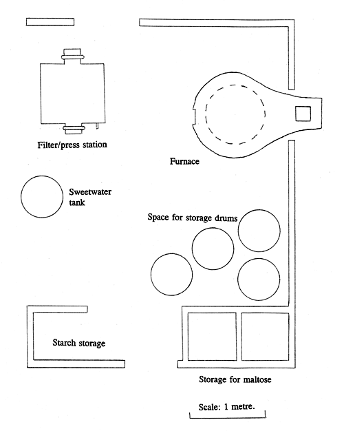
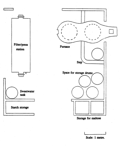
The scales provided are approximate and advisory - larger or smaller installations can be built as convenient. It has been found that the optimum distance from the furnace to the filter station should be 2 – 3 metres. Vessels do not need to be exactly the sizes stated and to some extent, weights can be proportioned.
The Furnace
To function properly, the chimney does not need to be more than about 1 metre high - it is shown 2 metres high in Figures 1 and 2 as it must be tall enough to carry hot gases safely out of danger and above the level of the roof of the building in which the furnace is housed. The cross sectional open area of the flue should be between 400 and 500 cm2. The flue should be roughly square, with sides between about 20 and 25 cm. Care should be taken to avoid leaving too much mortar waste on the inside of the flue. The outside dimensions of the chimney will depend on the shape and size of the bricks. If commercial bricks which have been properly fired are available, they should be used - sun-dried clay bricks will be too quickly damaged unless they are strengthened by adding some cement. If they are available, proper fire bricks are best for the archways and the chimney.
The following refers to the one pan furnace, or to the lower part of the two pan furnace - the support for the upper pan is merely two curved walls of mud reinforced with bricks, similar to the support for the lower ring.
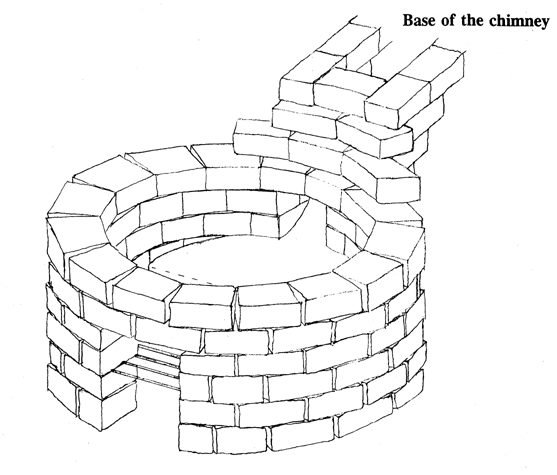
The furnace is a roughly circular clay ring (shaped according to the plan and strengthened with bricks) on a sloping floor. Figure 13 (below) shows how the bricks used for reinforcing the ring for the one pan furnace shown in Figure 1 should be assembled, although for the weight the ring needs to carry, making it entirely in bricks is not really necessary. A maximum of about 150 bricks will be needed for this ring, depending on the dimensions of the bricks. The floor should slope about 20 cm over a distance of a metre. At the lower end, the ring should be about 50 cm high and at the upper end, the top of the ring (which should be level) will be about 30 cm above the floor. The thickness of the ring is not important - if fewer bricks are used than in the attached sketch, the ring might be made correspondingly thicker - it only needs to be strong enough to take the weight of the heating vessel full of juice (150 – 250 kg). The ring should be sized so that it will support the heating vessel around its bottom rim, leaving as much as possible of the bottom of the vessel exposed to the burning fuel. There should be gaps in the ring, 20 – 25 cm wide at both the upper and the lower end. The lower gap should be bridged by two layers of bricks (the top of the top layer being level with the bottom of the heating vessel) and the gap at the upper end bridged by a number of layers which should be stepped to form a sloping tunnel leading to the chimney. The beginning of the tunnel leading to the chimney can be seen in Figure 13. The sides of this tunnel support the arch over the top of the tunnel and form the base of the chimney. The underside of each arch can be strengthened using a piece of metal - for example, a leaf from the rear suspension of a truck, but a space should be left at each end to allow for expansion of the metal. The cross sectional area of the tunnel should not be less than about 500 cms2 (about 25 cm × 20 cm) at its smallest point. The top of the lowest layer of bricks over the upper gap should form part of the ring on which the heating vessel sits and should therefore be level with the bottom of the heating vessel - see Figure 1. The circle on which the heating vessel sits should be complete and level.

Figure 13. The arrangement of bricks for the furnace.
Under about half of the area of the heating vessel (the lower pan in the two pan furnace) there is a grate - there is no grate below the upper pan, which is heated by the hot gases from the lower pan. The grate consists of a row of iron or steel bars on which the fuel is burned. There should be about 20 cm clearance between the bottom of the bridge and the grate (so that wood can be added as necessary without removing the heating vessel) and about 20 cm clearance between the grate and the floor (so that ash can accumulate without stopping the air flow. The back end of the grate is closed off with a step in the floor. Metal doors should be made to fit the openings, so as to allow the gaps above and below the grate to be closed off. Closing the lower opening will reduce the amount of air flowing through the burning fuel, thereby cooling the fire. Closing the upper one will reduce the amount of air sweeping away the heat. A little practice will quickly bring insight into how to regulate the two air flows to optimize the combustion of the fuel.
The Filter and Pressing Station
As with the furnace, the dimensions for the filter and pressing equipment shown in Figures 5 – 11 are not critical. The filter station is basically just a tank or a series of tanks, built with a base sloping enough to allow drainage of filtrate and expressed liquid with outside walls to contain liquid and splashes. The walls should have ledges that provide support to the lower platen during pressing. The station is best built of concrete or of bricks covered with a thick layer of cement - thin cement will quickly flake away from bricks. It is best to tile the inside surfaces, or to paint them before the tank is used for the first time. The thickness of the walls is not important. They should be approximately 10 cm thick at the top and they should have a step at least 5 cm wide along the inside, to support the lower platen. The depths of any additional tanks diminish as the floor slopes upwards away from the outlet - the individual depths are of no importance whatever. The outlet is made by setting a pipe through the bottom of the end wall. If there are additional tanks, there must also be drainage holes through the bottom of the dividing walls. A small loop of wire should be set in the outer wall about 25 cm above the outlet pipe. A 30 cm length of bicycle inner tube is tied tightly over the pipe and a hooked piece of wire is passed through the free end. When it is necessary to hold liquid back in the tank, the free end of the hose can be hooked up well above the liquid level. This stops the flow.
The platens for the press are best made of hard wood, although they can be made of metal. They must be sized to fit onto the step in the wall of the press station and they must be strong enough not to break or bend excessively when the pressure is applied. The normal design is a series of wooden slats which are nailed at either end to a cross piece. The cross pieces at the ends of the slats hold them in place and also provides support.
The sacks used for filtering are held open using a wooden frame 20 – 25 cm wide and long enough to bridge the tank. Protruding from the upper surface are spikes (nails) over which the mouth of a sack can be secured (normally 4 spikes are used for each sack).
Alternative Filtering and Pressing Equipment
Less expensive options for filtering and pressing are shown in Figures 10 and 11.


