Very few studies have yet been published which directly link GIS techniques to marine fisheries applications. This being the case it will be apparent that the studies shown here are mostly applications which have been made to peripheral areas in the field. The studies are therefore mainly concerned with GIS and the coastal environment, mariculture site selection or coastal zone management, or they are perhaps related to other marine fields such as hydrological surveying or the compiling of digital marine atlases. Nevertheless, there are sufficient studies for the reader to acquire a strong impression of the type of potential that GIS presently has to offer. Over the next decade we confidently predict that interest in, and developments of, GIS applications to marine areas will ensure that a rapid adoption rate will take place.
An attempt has been made to structure the content of the case studies in a sequence which looks first at some marine databases and digital atlases. These have been included, even though they are not really GIS's, because many of them either contain GIS generated maps or because there is an intention to eventually develop them into GIS's. We then include some example of coastal zone management and aquacultural GIS's because these provide working examples of marine associated practical GIS applications. Finally we include a miscellany of marine fisheries related GIS studies. Where possible the studies are related to the developing world. We have used the same structure for examining each case study, thus enabling the reader to gain some regularity in the subject content and its presentation. One problem which relates to some of the studies is that, although they all report the use of some level of GIS, there is very little factual information given on the specifics of the system, e.g. the type of software, the hardware configuration, or the amount of emphasis which was put into aspects concerning GIS per se relative to the overall subject matter being investigated.
| TITLE: | “Marine Resource Data Base (MRDB): A Database on Vulnerable Marine Resources in Norway.” |
| AUTHORS: | Selvik, J.R., Behren, H.L., Gjetrang, L.M., Langfeldt, J.N., Lystad, E., Marthinsen, I., Moe, K.A., Nedrebo, M. and Skeie, G.M. |
| PUBLICATION AND DATE: | Paper Presented at the ICES Statutory Conference. No. C.M.1993/D:44. Dublin, Ireland. |
Introduction/Objectives
It has been recognised that the Norwegian coastline contains some of the most important marine areas in the world, both regarding exploitable and non-exploitable resources. Many of these resources are already being heavily exploited, and there is a need to ensure that precautionary measures are in hand in case of accidents or emergencies. For this reason a consortium of nine major companies operating on the Norwegian shelf waters commissioned a group of marine scientists in 1987 to develop a marine resources database (MRDB). They have been assisted in this project by other government agencies. The database is now available and it provides information on the whole of the coastal area for mainland Norway and for Spitzbergen, i.e. 57 000km of coastline as well as 950 000 km² of shelf and oceanic waters.
Methods/Equipment
The database used for holding the information is “4th Dimension”, an Apple Mackintosh” relational database. Data for the databases was obtained from more than 300 official publications or scientific articles, and information is included on more than 22 000 sites. There are 15 major files, which are related as appropriate. A special “sub-GIS” programme, called GEDAP, has been developed which interactively allows data to be displayed on previously vectorised digital maps at any resolution. An example is shown in Figure 9.1.
The information in the MRDB is categorised through a three tiered system. The main database areas covered which are of interest to fisheries include:
a) Marine mammal sites,
b) Aquaculture installations,
c) Commercial fisheries,
d) Fish resources,
e) Nature conservation areas.
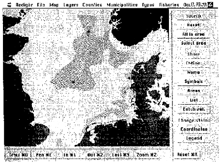
Figure 9.1 A Typical Screen Display for the Norwegian MRDB, Showing the Distribution of Mackerel Eggs in the North Sea in June, 1990
Within each of these major categories there is information where appropriate, relating to fields such as - administrative unit, location, conservation criteria, species information, etc. From each of these there are subtypes. Thus species information may include - eggs, larvae, spawning areas, 0-group, nursing area, post larvae, fingerlings, etc. The authors outline the difficulties which they experienced in trying to unite data which had its origins in many diverse sources. Typical difficulties included error correction, adding geo-references, incomplete data sets, differing data interpretations, etc.
Results/Discussion/Conclusions
The data is now available for use. One of the main uses has been in putting together Environment Impact Statements, though it is also being used in modelling likely environmental impact scenarios, e.g. to show what would happen to a species spawning ground if a pollution incident occurred given a certain date, wind speed and direction, quantity of pollutant, etc. The system appears to be functioning particularly well, and a Microsoft Windows based version for PC's has already been released. As the authors note, at the present time this system is really only a database with a mapping graphics add-on which has an extremely limited recognisable GIS functionality. However, it is important to stress that the system as outlined is one legitimate way of entering the GIS field, and it would take very little extra work to add functionality to this basic system. As the quality of the databases improve, this is undoubtedly what will happen.
| TITLE: | “The Skagex Atlas - User's Guide.” |
| AUTHORS: | Ostrowski, M. |
| PUBLICATION AND DATE: | Funded by International Council for the Exploration of the Seas (ICES) and the Nordic Council of Ministers. Bergen (1994). |
Introduction/Objectives
The Skagex Atlas is a computerised data atlas consisting of a set of databases plus their managing software. It contains all the data collected by marine scientists from seven Baltic area countries, whilst carrying out joint fieldwork in the Skagerrak and Kattegat Seas during 1990 and 1991. Data was collected on physical, hydrochemical and biological parameters and then centrally submitted to the ICES Data Centre, who worked them up into a coherent database. In order to make this database more accessible to all the SKAGEX scientists, in 1991 the author proposed that he use his in-house software, a marine data management system, to create the Skagex Atlas. In April, 1992 the first version of the digital atlas was ready. It has since been refined and updated.
Methods/Equipment
Contrary to its name, the Skagex Atlas is not a ready set of digitised charts. Instead it is a collection of databases carrying the results of all the in situ sampling carried out by the Skagex marine scientists. The database is divided into records, each of which corresponds to an oceanographic station. The records (stations) are indexed by platform (ship) identifiers, and location/time coordinates of each sampling event. For each station the datacycles with results are structured into a simple table where columns pertain to parameters and rows to depth levels. The Atlas software provides integrated tools for browsing and downloading data subsets from the databases. All subsets can be visualised in terms of x-y plots, sections and maps showing horizontal distributions of the sampled parameter (Figure 9.2). The atlas's own software is linked with a commercial 3-D graphics package called SURFER to produce this output.
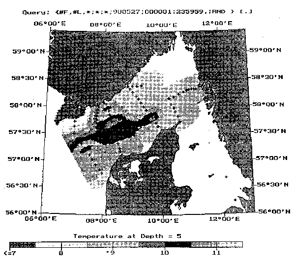
Figure 9.2 Example of Skagex Atlas Output Showing a Black and White Copy of a Colour Raster Image of Temperature Distributions at 5 Metres Depth on 27th May, 1990
The data forming the databases was collected from 17 stationary oceanographic vessels using probes and water bottle samplers. Samples on the main parameters of temperature, salinity, phosphate, nitrate, nitrite and silicate were taken from up to 15 different depths, ranging from 1 to 600 metres. Most of the data was collected along seven obligatory tracts during May and June of 1990 at coordinated times (Figure 9.3). Whilst not collecting data along these tracts, vessels collected discretionary data which is also in the main ICES database and is accessible to the Atlas. Some of the obligatory transects were re-surveyed at later dates in September, 1990 and/or January, 1991. As of 1994, data sets covering primary productivity of phyto- and zoo-plankton were not accessible, though they will be available at a later data.
The Atlas software is designed to run on IBM PC computers having a hard disk. It requires 15MB of free disk space for the databases. The minimum hardware configuration should include an 80286 processor plus a maths coprocessor and 600Kb of free RAM memory. The Atlas is user friendly being menu driven usually with the use of a mouse. Colour display is optional. The hard disk should also contain Microsoft DOS version 5.0 or higher plus the SURFER 3-D graphics package (version 4.11 or higher). The Atlas software can now also be run from Microsoft Windows.
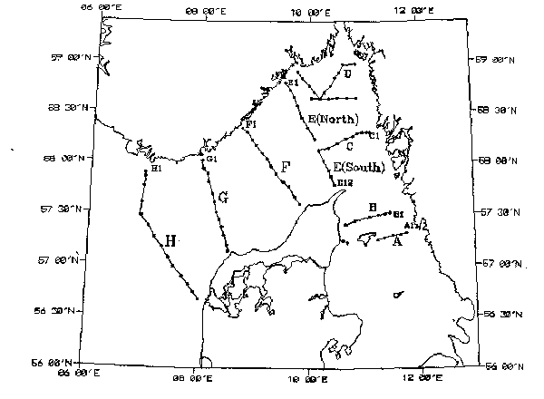
Figure 9.3 The Main Transects from which Data was Gathered for the Skagex Atlas
Results/Discussion/Conclusions
This Atlas is clearly an example of a fairly basic way in which some GIS functionality can be obtained. Thus the Atlas software allows the databases to be transformed such that visual mapping displays are obtained for a range of parameters, and the user has a degree of control over the output required. The User's Guide sets out in detail all the various commands (the user interface), and how to process the data into a form for presentation of maps, sections or graphs. It also outlines the various printing or plotting capabilities.
| TITLE: | “Marine Resource Atlases: The Implications for Policymakers and Planners.” |
| AUTHORS: | Ramster, J. |
| PUBLICATION AND DATE: | Underwater Technology. 1994. Vol.19, No.4. pp12–19. |
Introduction/Objectives
In this case study we shall review the United Kingdom Digital Atlas Project (UKDMAP), although the journal paper also looks at other similar atlas and marine database developments. UKDMAP has also been described in Ramster (1991) and Robinson (1991), though both of these papers describe version 1. The UKDMAP was developed by the British Oceanographic Data Centre (BODC), in collaboration with other data providing agencies, as a reference work on the seas around the British Isles. Version 1 was released early in 1991, version 2 in mid 1992 and a Windows version has recently been released. The Atlas contains 462 different maps (charts) under the variety of different datasets shown in Table 9.1. For every one of the charts there is an “Information” box, which provides varying details on the chart, its data sources and where further information can be obtained.
| * General reference | 18 charts |
| * Marine geology and geomorphology | 11 charts |
| * Marine and coastal parks, reserves and protected areas | 15 charts |
| * Marine and coastal conservation in Great Britain | 8 charts |
| * Sea birds | 25 charts |
| * Sea mammals | 11 charts |
| * Marine biology | 29 charts |
| * Currents, tides and surges | 19 charts |
| * Winds, waves and weather | 21 charts |
| * Seawater temperature, salinity and nutrients | 162 charts |
| * Chemical distributions | 33 charts |
| * Exploitation of the marine environment | 12 charts |
| * Fishing areas and fish spawning areas | 24 charts |
| * Fishery statistics | 50 charts |
| * British Oceanographic Data Centre - data catalogues | 24 charts |
Methods/Equipment
The Atlas runs on an IBM PC with 640Kb of RAM, an EGA or VGA display and a hard disk with at least 10MB free for running and installation. It uses the Microsoft DOS operating system (Version 3.0 or later), preferably a mouse and it can be networked for multi-user operation on a LAN. Output to most laser or dot matrix printers is possible.
The Atlas is very “user friendly”. It is controlled by a system of pull down hierarchical menus, backed up by a context sensitive help system. Information within the Atlas is presented as a series of colour charts which the user may browse, zooming into areas of specific interest, and overlaying with information from another chart for comparison purposes. The “Information” boxes can be superimposed on charts for reading or printing. Figure 9.4 gives examples of UKDMAP output. There are options to change or customise any of the colour shadings on the charts as required, and to place a reference grid over any chart. There is also an interactive cursor which allows latitude and longitude coordinates to be read, or which allows distances to be calculated along user plotted lines at any scale. The atlas has a “save screen display for slides” allowing charts to be viewed outside the system using the “Slideshow” programme provided.
Results/Discussion/Conclusions
Digital atlases of this kind offer a number of advantages over traditional atlases. Thus the user has the ability of manipulating the presentation of charts to his advantage according to specific needs. Scale changes can be instantly carried out. Bringing out a new addition is simple in the sense that adding new information to any disks for retailing in an updated version, is a far cheaper proposition than reprinting and supplying a new hardcopy edition of such an Atlas. This also means that a far greater range of material can be provided for comparatively little extra effort. The success of this Atlas format has been such that several new and similar marine atlases are planned by the British Ministry of Agriculture, Fisheries and Food.
Although the Atlas is not a true GIS, it goes some way to providing some limited functionality of a GIS. Thus the overlay facility, querying and distance measurements are all basic GIS prerequisites, and they provide excellent illustrative concepts of what the scope of a GIS might begin with. Also, this type of product could well take on board more GIS analytical capabilities in future releases.
| TITLE: | “Protecting the Environment: GIS and the Wadden Sea.” |
| AUTHORS: | Liebig, W. |
| PUBLICATION AND DATE: | GIS Europe. Vol.3, No.2. pp34–36. 1994. |
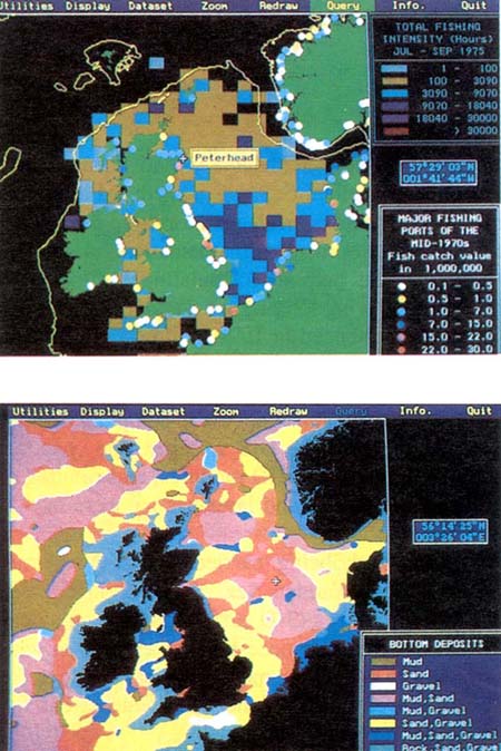
Figure 9.4 Examples of output from the United Kingdom Digital Marine Atlas
Introduction/Objectives
The Wadden Sea consists of about 8000 km² of sheltered waters which stretch along the coastline of mainland Europe between northern Holland and western Denmark. The Sea forms a somewhat unique natural habitat consisting of very shallow waters, having strong tidal currents, and being surrounded by flat islands of sand and grasses, plus dunes, beaches, salt marshes and tidal flats. This environment is presently under threat from dyke building, agriculture, fishing, tourism and recreation, plus pollution from the North Sea and nearby rivers.
In order to give a measure of protection to this coastal environment, the Danish, German and Dutch governments have declared that much of the area should be designated as protected national parks. Allied to this a number of research stations have been set up, and projects have been instigated, which have an interest in studying the area's hydrology, geomorphology and biology, plus the various impacts on this fragile environment from human activities. This particular study was carried out from the Coastal Research Station at Norderney in northern Germany.
Methods/Equipment
Since a large number of spatially related databases had been set up, and since there were sufficient and varying existing maps, then GIS was considered to be an appropriate tool for the analysis and representation of the hydrological, geomorphological and biological data and their interactions. This included the development of mathematical models to show simulated current and wave movements which would help in formulating sediment transportation paths. The Research Station was fortunate in having long term data covering, for some data, the period back to 1650. The actual GIS work commenced in 1990, and GIS is now being used for a variety of projects.
All the data gathered are held on a mainframe VAX computer which itself formed part of a Local Area Network (LAN), of which the GIS was just one constituent. The GIS used was ARC/INFO, incorporating their TIN and GRID modules, and running on a DIGITAL-5000/125 workstation. A DIN A/O digitiser, plotter and laser printer were also used.
One of the main purposes of work being carried out at Norderney is to investigate the morphological development of the Wadden Sea. Once digitised maps had been produced, Triangular Networks (TIN's) and lattices (3-D surfaces) could be calculated, the latter forming the basis of a regular grid. This grid was necessary as a basis on which to perform inter-cell comparisons, i.e. to show, and to calculate, morphological changes from one date to another. The grid was also used in the development of the wave and current flow models.
Results/Discussion/Conclusions
For some of the GIS output it was simply a case of digitising various maps in order to create separate layers, and then to use the GIS to combine these layers to produce new maps. Figure 9.5 is one such example. It shows, at a fairly small scale, the Wadden Sea area for the German state of Niedersachsen. The green areas represent offshore islands, and the orange represents the tidal flats. For one detailed area of the map the sediment distribution is shown, though more detail on sediments and wave heights in this area is given in Figure 9.6. Information on wave heights has been calculated using a specially developed mathematical wave propagation model which allows height to be calculated at all of the lattice points, i.e. given various wind and morphological conditions. The GIS was used not only to prepare the maps, but also to calculate various combinations of wave parameters such as height, length, and period at each lattice point. These types of map typify the GIS output which is requisite in coastal zone management studies. From these two Figures it is clear that GIS is being used here in a very specific and fairly sophisticated way, and the author is able to show a number of other uses to which the GIS has already been put. Thus analyses have been done which relate wave height to channel depth or wave height to sediment type, and which explain changes in morphological characteristics over time. This work should go some way to resolving the dynamics of the assorted natural processes which are occurring in the Wadden Sea area, thus ensuring a better long term future. This is important since, although the author does not mention it, parts of the Wadden Sea form the major nursery area for the southern North Sea plaice stock, one of the major commercial fisheries in Europe.
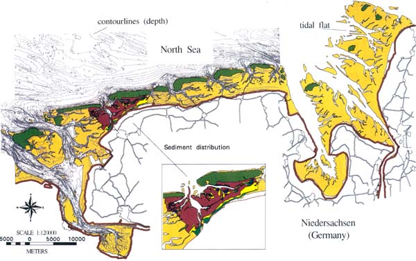
Figure 9.5 Coastal Zone Map of the Wadden Sea Area Of Northern Germany
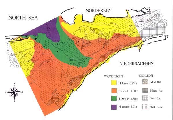
Figure 9.6 Wave Height and Sediment Distribution Over Tidal Flats Near Norderney, Northern Germany
| TITLE: | “Use of High Resolution Satellite Data for Coastal Fisheries.” |
| AUTHORS: | FAO |
| PUBLICATION AND DATE: | FAO Remote Sensing Series No.58. 1991 |
Introduction/Objectives
This study is one in a series of publications which have been published by the FAO, and which are aimed at presenting various project managers with the possibilities that are offered by the use of remote sensing as an aid to resource management. This case study does not actually use GIS directly, but it is an excellent example of how data can be gained which is both in a correct format and of a high quality i.e. such that it can be directly input into a GIS.
The coastal zone in many developing countries is under tremendous pressure, especially certain fragile environments such as mangroves or coral reefs which are effected by a variety of marine and land based economic activities, and which are easily destroyed. In many areas of the world these coastal areas have been insufficiently mapped for management or monitoring purposes. The main objective of this study was to show how remote sensing capabilities (specifically the use of SPOT imagery) are now such that they can allow for extremely detailed maps to be drawn up, in this case showing all the features associated with an intertidal zone in Quezon Province of central Luzon in the Philippines. This region is naturally covered by mangroves plus areas of coconut trees, and some mariculture facilities are already in operation. The population density is high and most people are employed in small scale coastal fisheries.
Methods/Equipment
All the necessary image processing was carried out at the FAO Remote Sensing Centre in Rome. A SPOT image dated 5th February, 1988 was used as the basis for the exercise. This image, in multispectral mode at 20 m resolution, was pre-processed by SPOT to level 2A in the UTM cartographic projection. Some land use maps were also used in the production of the final map output. Ground truthing was necessary as a means of verifying the reflectance values, and field surveys were undertaken for this covering aquatic and terrestrial environments. Obviously, before final output could be obtained various image processing procedures were necessary, and these are described in detail in the original text.
Results/Discussion/Conclusions
Figure 9.7 shows a final map which was published. The scale is at 1:50 000 and the imaging processing methods used allows the map to differentiate between a large number of tidal and shallow water features. The terrestrial features shown would have been added using information from local topographic map sources. Of prime interest for fisheries purposes, the map gives indications of:
a) The coastline. This is of a high resolution and the satellite data could provide an outline which was geometrically correct.
b) The intertidal area. It was possible to distinguish a number of separate land use categories and existing aquaculture ponds. c) Shallow water areas. In clear waters up to a depth of 10 metres it was possible to identify both bottom types and to draw 3m and 10m bathymetric lines.
The maps could be used to update nautical charts, to locate seaweed resources, to select potential aquaculture pond or cage sites, to monitor the environment or to assess existing land uses.
This project was also able to calculate the relative costs of obtaining this type of information, and it was found to be cost effective vis a vis the main alternatives. Because of the number of complex processes involved before the final product could be produced, this type of mapping data can take some time to achieve, e.g. perhaps a one year period to obtain details on up to 20 000 km² of coastal zone. With new satellite programmes coming on stream, and with the release of much previously unavailable Russian data, then future costs of obtaining data in this way are likely to fall. Although the work for this study was done by the FAO in Rome, the publication states “… technology transfer to a developing country can be accomplished with minimal international assistance at a reasonable cost.”
| TITLE: | “Coastal Zone Mapping.” |
| AUTHORS: | Harper, B. and Curtis, M. |
| PUBLICATION AND DATE: | Mapping Awareness & GIS in Europe. (1993) Vol.7, No.1. pp17–19. |
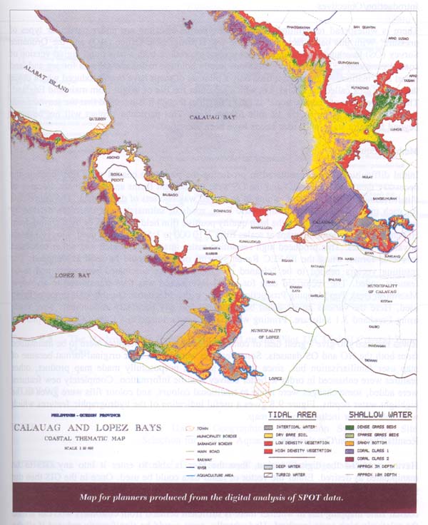
Figure 9.7 Map Showing Coastal Intertidal and Shallow Water Zones for Part of the Lamon Bay Area of Luzon Island in the Philippines
Introduction/Objectives
There is widespread recognition that various types of coastline are under particular types of pressure. With this basic fact in mind, the UK Hydrographic Office (HO) and the Ordnance Survey (OS) have undertaken a joint pilot project to produce both a paper and digital version of coastal zone maps. These two organisations jointly hold the national databases for sea and land based information. At the present time only a pilot set of maps have been produced which cover the marine area called the Solent, i.e. which separates the Isle of Wight from mainland England. The interpretation of “coastal zone” is rather flexible, though it is intended that the seaward side should range out as far as the 12 mile fishery limit. This particular project will not be taken beyond the pilot stage until user needs have been identified.
Methods/Equipment
Initial difficulties were encountered in producing the prototype coastal zone map because the necessary data kept by the HO and the OS were in different forms and/or formats. Because of this it was not simply a case of joining in an agreed way two sets of digital data. The digital data for each mapped theme, e.g. bathymetric lines, roads or saltmarsh, was therefore derived by selective scanning, either from the high quality positive film held by the OS or by scanning from HO charts. OS topographic maps at scales from 1:10 000 to 1:50 000 were used, plus HO charts at various scales. This produced high resolution raster image data, which was either converted to vector format using the PAFEC Raven system, or which could be used as obtained. The resulting vectors needed to be “cleaned up” using various automated processes, and to be features coded. The vectorised data for all 32 layers used was then transferred to an Apple Macintosh Desk Top Mapping Production system, with a Macintosh Quadra 700 computer being used. Here the various layers could be combined and any necessary refinements were made using Freehand 3.1 software. Printing was via the screen image to a Canon CLC10 copier.
It was necessary to give a great deal of consideration as to which features were to be maintained from both the HO and OS datasets. Some features were left in their original format because of map user familiarisation but, since this was to be a purposefully made map product, other features were enhanced in order to better convey specific information. Completely new features were added, some changes were made to traditional colours, and colour fills were given to the highlight water depths. Figure 9.8 gives a useful indication of the hydrographic features which were selected for inclusion on the map.
Results/Discussion/Conclusions
Having acquired the digital version, then the user is able to enter it into any GIS to be manipulated as desired. Either the vector or raster data could be used. Once in the GIS then the possibilities for its use are huge. Figure 9.9 illustrates how a user has overlaid his own vegetative data on the basic coastal zone map. The main problem with regard to further digital coastal zone mapping lies in whether there is sufficient demand from customers who can afford the relatively high costs involved. Undoubtedly, costs would be significantly reduced if all the initial data required were to be held in a digitally standardised form.
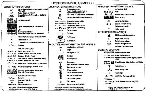
Figure 9.8 The Hydrographic Symbols Displayed on the Pilot UK Digital Coastal Zone Map
| TITLE: | “The Use of Geographical Information Systems for Site Selection for Coastal Aquaculture.” |
| AUTHORS: | Ross, L.G., Mendoza, E.A. and Beveridge, M.C.M. |
| PUBLICATION AND DATE: | Aquaculture (1993). Vol. 112, No. 2–3, pp165–178. |
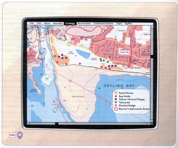
Figure 9.9 A Displayed Portion of the Pilot Coastal Zone Map Overlaid with User Defined Vegetation Occurrences
Introduction/Objectives
Although growth in aquaculture has been quite spectacular recently, there have also been a large number of business failures. One of the reasons for this has been a lack of knowledge on the aquatic environment and the use of unreliable means for resource assessment. To plan successfully it requires both reliable data and a way of processing the data. Until recently the means of processing the data has often been limited, and the acquisition of reliable data is still a problem throughout much of the world. The advent of GIS as a tool for planning has now become accepted, and some applications in aquaculture development have already been made. Most of these have been carried out at the regional scale. This study seeks to show the use of GIS for detailed site selection at the micro scale. The paper describes the implementation of a PC-based GIS to assess the potential for salmonid cage culture development in Camas Bruaich Ruaidhe, a small bay in Argyll, Scotland.
Methods/Equipment
The GIS software used was “OSU-MAP for the PC”, a raster based package developed at the Ohio State University. Though the software is very unsophisticated, it is well suited to small research projects. A 80386 processor was used plus an HP7475A plotter and an HP Laserjet IID printer. Although the study was first reported by Mendoza (1990), and was outlined in Meaden and Kapetsky (1991), the work has been substantially advanced since then.
For input into the GIS, data had to be gathered on the following production criteria:
(a) Topography. A detailed topographic map had to be drawn up, using plane tabling and levelling techniques, at a scale of 1:2000.
(b) Bathymetry. A bathymetric contour map was prepared by using a Lowrance echosounder to take readings in several transects across the bay. This was plotted out at a scale of 1:2000, with a 2 metre contour interval.
(c) Currents. Current velocities and directions were measured at different tidal states using hydrographic drogues.
(d) Exposure. This was classified by estimating wave height at different locations. Wave height would depend on wind direction, velocity, duration and fetch. Wind data was obtained from a nearby weather station and fetches were calculated from a local topographic map. Heights were predicted using graphs available in published sources.
(e) Water quality. Vertical profiles of dissolved oxygen, salinity and temperature were made from a number of different locations in the bay.
Data on the above parameters were prepared for input to the GIS at two different scales so that a comparison of the results could be made. Scales were chosen so that each data block represented either a 25 x 25 metre cell (total 576 cells) or a 10 x 10 metre cell (total 3600 cells). Data values were calculated by laying a transparent grid base over the appropriate mapped representation of each production criteria, and then reading off the values. Other information was added to the database by taking the information straight from topographic maps, e.g. the outline of the bay and the location of main roads.
Results/Discussion/Conclusions
Generally, the bay should make a good site for coastal aquaculture. It is easily accessible, electricity is close by as are labour supplies, services and other supplies. There is also no source of pollution nearby, it is little used as a recreational resource and there are no shipping lanes to be wary of.
The authors produce for discussion maps on each of the production criteria. The main findings on each were:
(a) Bathymetry. The mean depth of the bay was 6.8m, and about half of the bay had suitable depth profiles.
(b) Currents. There was an anti-clockwise current pattern with highest velocities of about 130 cm per second occurring along the eastern side of the bay. 80% of current speeds were within acceptable limits.
(c) Dissolved oxygen. Levels varied slightly between high and low tide, but they were in the range of 8.2 to 11.0 ppm. Vertical profiles were uniform. DO was not considered to be a limiting factor.
(d) Water temperature. This varied from 12.8 to 13.0 C. Although there would clearly be seasonal variations, these were not within a range where limitations would be placed upon production.
(e) Salinity. Although there was no vertical stratification of this parameter, there were clear differences between ebb and flood tides. These were sufficient to make a marked difference in the aquatic environment and therefore to the salmonid production potential.
(f) Wind speeds. This parameter was also highly variable, mostly according to length of fetch. Wave heights were calculated and mapped such that a worst case situation was allowed for.
Having established the existing parameters, the authors then used a processing sequence for site selection. This essentially meant that, having decided upon suitable parameter ranges for aquacultural production, then scores had to be allocated according to the degree of suitability (Table 9.2). Once the scoring sequence had been undertaken, then cells showing the highest scores should prove most suitable (Figure 9.10).
The map which had a resolution of 25 × 25m cells was found to be of too coarse a resolution, though the authors suggest that this scale may be alright if a very large raft of cages were having to be sited. Though the GIS approach was considered to be very satisfactory, there would continue to be a problem in obtaining some of the data. So, for instance, it is doubtful if suitably detailed bathymetric data would ever be available, and data on current velocity, water quality and wave height would also need to be calculated from field investigations in what could be a costly and time consuming process. As a general comment, care would also need to always be taken when constructing maps based upon interpolated data covering large areas in dynamic environments. From a time/cost perspective, estimations on the use of GIS vis a vis manual methods proved GIS to be very efficient i.e. the time taken to process all the data manually was about 40 hours, whereas only 19 hours were needed to process the data for GIS use.
It is important to recognise sources of error which may result from the GIS approach. These may be due to inaccurate source data, poor parameter choice and inappropriate scoring methods. The authors were able to compare the GIS results with those done by a manual survey carried out by nine skilled volunteers. It is interesting to note that the manual survey found that about 40% more of the bay was suited to aquaculture than the GIS survey found, but there was a huge variation between individual assessments. This could show that manual assessments are prone to bias, and this large variability could have severe economic implications for an aquacultural development.
| Source Layer & Resultant Layer |
Process step |
Scoring criteria |
Scores |
|---|---|---|---|
| BATHY | Select depths over 6m | Less than 6m 6m and above | 0 1 |
| BATHGRAD | |||
| WAVEDIST | Cross with BATHGRAD and score | Wave height
<60cm Wave height >60cm | 1 2 |
| SAFEWAVE | |||
| CURR-INT | Cross with SAFEWAVE and score | Waves <60cm Currents <50 cm.sec-1 Currents >50 cm.sec-1 Waves >60 cm Currents <50 cm.sec-1 Currents >50 cm.sec-1 | 1 2 3 4 |
| BAWVCURR | |||
| SALEXT | Cross with BAWVCURR and score | Salinity variation 8ppt >8ppt | 1 0 |
| *D.O. | Cross with BAWVCURR and score | D.O. <6mg.1 D.O. >6mg.1 | 0 1 |
| *TEMP | Temperature
<5 °C 5–10 10–15 >15 | 0 1 2 1 | |
| FINAL | |||
| FINAL | Cover SITE with FINAL to show end result | ||
| SUITABLE | |||
* These were not considered in this GIS
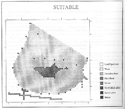
Figure 9.10 Cells Which Should Prove to be Most Suited for Salmonid Aquaculture in Camas Bruiach Ruiadhe Bay, Scotland
| TITLE: | “A Geographical Information System to Plan for Aquaculture: A FAO-UNEP/GRID Study in Costa Rica.” |
| AUTHORS: | Kapetsky, J.M., McGregor, L. and Nanne E., H. |
| PUBLICATION AND DATE: | FAO Fisheries Technical Paper No. 287. (1987) |
Introduction/Objectives
The authors initially outline the reasons why, despite the tremendous needs, the planning process itself for developments such as aquacultural facilities has been very slow to materialise. With the emergence of GIS capabilities, there is now the a means whereby the manipulation, analyses and evaluation of large amounts of data is possible, such that reliable decisions concerning locations and development planning can be made. The particular objectives of this study were to establish the feasibility of using remote sensing and GIS as tools in assessing the opportunities for coastal aquaculture, and to see where the most promising opportunities were for this aquaculture (including how much land and water was available).
The area of study chosen for these tasks was the Gulf of Nicoya, on the Pacific coast of Costa Rica. This area was selected since its environment offered the essentials for aquaculture, since there was strong competition for local land resources, and because there was already some culturing going on here which would offer the opportunity to check the results obtained against any existing information. The present culturing consisted of some semi-intensive shrimp ponds although the development of mussel culturing is under investigation. The authors give a detailed geographic study of the relevant physical and social conditions which exist in the Gulf area. The main factors to note are:
(a) The Gulf shoreline is mainly fringed with mangroves interspersed by hilly areas.
(b) The surrounding land is mostly pastoral.
(c) There few large centres of population.
(d) Year round temperatures are high and there is a rainy season from May to November.
(e) The waters at the head of the Gulf are mostly less than 20m deep, though they rapidly deepen towards the entrance.
(f) There are extensive inter-tidal flats at the northern end of the Gulf.
(g) Salinity is a function of the tidal state and the season and also of current flows which cause the eastern side to be less saline.
(h) Water temperatures are in excess of 25 C but tend to be stratified in the dry season.
(i) Dissolves oxygen levels are frequently low in the upper Gulf, especially during the dry season, i.e. given the low water change and high primary productivity.
(j) High levels of ammonia result from water run-off from the pastoral lands.
The bulk of this study is focused on the inner Gulf area where it was obvious from an initial analysis that more aquaculture potential lies (Figure 9.11). In this area the greatest potential would seem to be in (i) the raft or longline culturing of molluscs in intertidal and subtidal waters, (ii) the extensive culturing of shrimp in former solar salt ponds and (iii) semi-intensive shrimp production outside of mangrove areas.
Methods/Equipment
The software used in this study was ELAS, which is essentially an image processing system with the capability of integrating other geo-referenced data. The hardware used included a Perkins- Elmer 3241 computer and a Calcomp 6000 for digitising. Analyses and processing were carried out at the Global Resources Information Database (GRID) facility in Geneva, Switzerland.
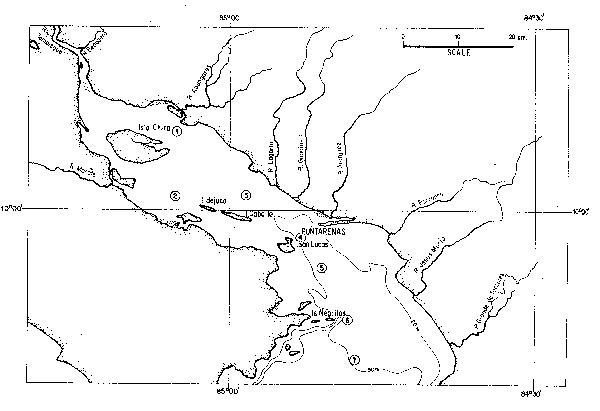
Figure 9.11 General Features of the Gulf of Nicoya, Costa Rica
The criteria used to assess aquaculture potential are shown in Table 9.3. For each of the criteria it was necessary to establish the range of conditions in which it would prove possible to function in and to identify optimum conditions. A variety of methods was used to obtain the necessary data. Thus salinity level data was obtained from previous survey data, bathymetric data from published nautical charts, and shelter and security data was based on wind speed meteorological data adjusted so as to provide an indication of the likely wave height according to the fetch and water depth. Information on land use was obtained from a Landsat Thematic Mapper image dated 15 April, 1985 and verified by ground truthing during July, 1986. The existence of the solar salt ponds was also obtained from this image. Water quality data was inferred from land use, i.e. such that mangroves gave best quality water, then forest, then rangeland, then pasture and finally cropland would result in the worst quality water. Information on the infrastructure was obtained from the national topographical mapping series at 1:500 000 scale. Soil data was obtained from national soil maps at 1:200 000 scale and their suitability for pond lining was assessed and given a “relative suitability” score. The authors explain in some detail both the purposes for including the “proximity” and the “shrimp post-larval density” data, and the ways in which this data was calculated from existing information.
| Organisms and Culture Methods | |||||
|---|---|---|---|---|---|
| ------------Molluscs------------ | |||||
| ------------Fishes------------ | |||||
|
Main Criteria | ------------Shrimps------------ | ||||
|
and Sub-Criteria | Intertidal | Subtidal | Suspended | Extensive | Semi-intensive |
| Salinity | X | X | X | X | X |
| Infrastructure | X | X | X | X | X |
| - Villages | |||||
| - Roads | |||||
| - Ferries | |||||
| - Processor | |||||
| - Electrical service | |||||
| Land Uses | |||||
| - Water Quality | X | X | X | X | X |
| - Site acquisition costs | X | ||||
| - Site development costs | X | ||||
| - Mangroves | X | X | X | ||
| Bathymetry | X | X | X | ||
| Shelter and Security | |||||
| Shrimp post-larvel density | X | X | |||
| Proximities | |||||
| - Perennial rivers | X | ||||
| - Saltwater | X | ||||
| Soils | X | ||||
Results/Discussion/Conclusions
The authors initially provide a very detailed analysis of the potential for aquaculture under each of the three main types envisaged (as listed above). Space here prohibits a detailed review, but a summary of their findings would be:
(a) Intertidal, subtidal and suspended culturing. About 14% of the inner Gulf would be suitable for this activity. The best areas are in the vicinity of Chira Island. Altogether, there are about 9 000ha of subtidal waters which are both sheltered and suitably protected. In the main these areas have the requisite lower salinities for the rearing of euryhaline organisms. One problem with these optimum areas is their relative isolation from the main urban area of Puntarenas, although it is likely that counter benefits will be obtained from the higher quality waters. About 950ha of intertidal water was found which would prove suitable for aquaculture. Figure 9.12 shows the optimum locations for the three types of culturing; purple indicates areas of mangroves.
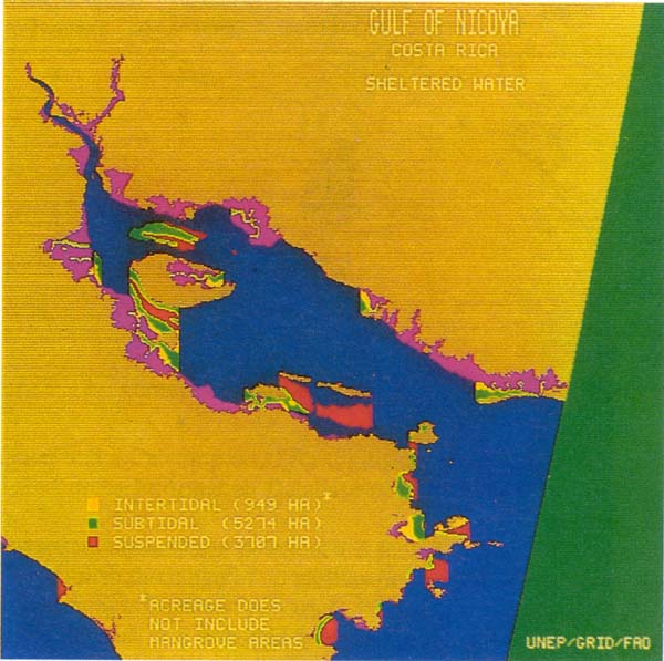
Figure 9.12 Location and Surface Areas for the Development of Intertidal, Subtidal and Suspended Cultures in the Gulf of Nicoya, Costa Rica
(b) Extensive aquaculture in solar salt pans. 80 salt pans having a total of area of 656 ha were detected by satellite remote sensing. Those which offer the best aquacultural potential will be where shrimp post larvae from the wild are most abundant, where pond salinities can be manipulated and those which are supported by good communications to the markets at Puntarenas. Some 23% of the available salt pond area was found to best meet the selection criteria, and these were mostly on the northern Gulf shoreline near to the mouths of rivers from where fresh water could be obtained. The infrastructure was also relatively good here.
(c) Semi-intensive shrimp farming outside mangrove areas. Some 2232 ha of land meet the necessary criteria for this activity. This falls into four areas on the northern Gulf shoreline and one in the south. Again it is the availability of the infrastructure which gives priority to these areas. The results obtained seem to justify the proposed methodology, though the authors rightly suggest that they are only indicative and that more detailed field investigations would be necessary before actual aquacultural sites were selected. One of the major problems to a study of this kind is the variability of the source data, i.e. both in its accuracy and scale. Therefore the use of GIS will only provide more reliable information when input data are more reliable. The authors suggest a number of ways in which the input data could have been added to, or improved upon, but to achieve this would require huge additional cost and effort inputs. The study concludes with an interesting analysis of the utility of using GIS and remote sensing in an exercise such as this. The conclusion is also of interest from the viewpoint that, since this study was produced in 1987, many of the conclusions concerning matters of cost and efficiency have been superceded through the pace of change in GIS developments and applications, i.e. such that GIS now has a far greater utility than it did a decade ago.
| TITLE: | “Using a Geographic Information System to Evaluate the Effects of Shellfish Closures on Shellfish Leases, Aquaculture and Habitat Availability.” |
| AUTHORS: | Legault, J.A. |
| PUBLICATION AND DATE: | Canadian Technical Report of Fisheries and Aquatic Sciences No. 1882E. (1992). |
Introduction/Objectives
Throughout much of the Atlantic seaboard area of Canada municipal sewage is disposed of directly to the sea without having been treated. The waters therefore become contaminated with bacteria, viruses and toxic chemicals. This situation is exacerbated by industrial discharges and agricultural run-off. Based on guidelines covering specific contamination levels, issued jointly by the Department of Fisheries and Oceans (DFO) and the Department of the Environment (DOE), the authorities are regularly forced to close the shellfish beds in specified areas for varying lengths of time. These closures effect both aquacultural and “wild” shellfish harvesting, and this action inevitably has a strong effect on the local economy. In order to monitor this situation and to try to produce a remedy, the DFO's Marine Atlantic Standing Sub-Committee on Habitat (MASSH) funded a pilot study to quantify the shellfish habitats affected and the shellfish markets lost or jeopardised as a result of the closures. The pilot study was based upon the eastern coast of Prince Edward island in the Canadian Maritime Provinces.
Methods/Equipment
The study utilised the Computer Aided Resource Information System (CARIS), which uses an INGRES relational database, running on a MicroVaxII with a VMS operating system. The author explains how the necessary digital mapping outlines and data on pollution sources and shellfish closures was obtained from various sources. As an end product, the GIS was expected to produce output showing the coastline features, shellfish closure zones, shellfish approved zones, shellfish leases, land-based pollution sources, plus corresponding tables of data.
Results/Discussion/Conclusions
It was found that the system was able to meet the above criteria except that the size of the hard disk space was insufficient for all tasks, and that the system needed to be more user friendly. Both of these problems could be easily rectified. The author shows and discusses examples of the variety of output which could be achieved by use of the CARIS system. These ranged from simple outline maps of the region, through maps showing the shellfish harvesting zones, maps showing the point sources of pollution, to maps such as Figure 9.13 which shows a specific portion of the area in some detail. Notice that lines can be generated which join given co- ordinates so as to delimit enclosed polygons (in this case individual or grouped rivers). This functionality is useful for indicating any shellfish closure areas. Area calculations can be made of the size of such closed polygons, and shading can be added so as to enhance the visualization of the map.
Since the input data to CARIS contained a large amount of varied database information, then a varied range of tabular output could be generated. Figure 9.14 illustrates tabular output, in this case giving an indication of shellfish production quantities likely under different production rates for individual leases along two main river estuaries. Unfortunately, it is not possible to provide information on monetary losses when closures occur, since shellfish sales are registered in terms of quantity sold per lease, and market values vary greatly during the season. Thus estimates of losses are registered in terms of area (or the leased area as a percent of the total area closed).
The author continues by showing how the use of GIS in this study can help provide financial estimates of the range of losses which might be expected, or the value to the economy of production from specific estuarial areas, under different levels of productivity. For these calculations it is necessary to derive estimated monetary values for the shellfish. This can be obtained from local market sources. Knowing the point sources of pollution, it is then possible to estimate the likely value of losses along an estuary, given a lethal pollution incident at any specified point. Additionally, since the pollution point sources are classified by type, e.g. factory, pig farm, tobacco farm, sewage outfall, etc, then the maps generated of these sources allow for relationships to be established showing which type of source is generally or specifically most harmful. Remedial action can then be taken. The author concludes by showing that in practice the GIS software and hardware could be expensive to purchase, and that data could also be very expensive. However, these problems could be mostly resolved if the government could make more data available in a suitable digital form, and if there was a unified policy concerning database management. At the present time there are insufficient incentives for making data more readily available.
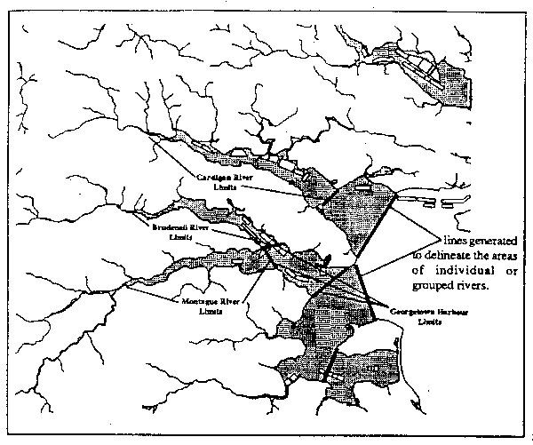
Figure 9.13 Map Showing Individual Shellfish Leases in Eastern Prince Edward Island, Canada
| TITLE: | “A Geographical Information System for Some Mediterranean Benthic Communities.” |
| AUTHORS: | Meaille, R. and Wald, L. |
| PUBLICATION AND DATE: | International J. of Geographical Information Systems. (1990). Vol.4, No.1. pp79–86. |
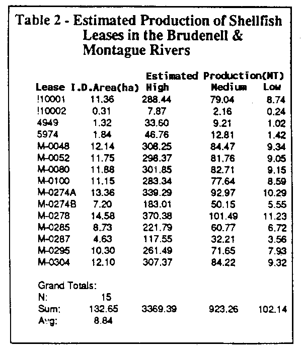
Figure 9.14 Example of Tabular Output from the CARIS GIS on Shellfish Leases in Prince Edward Island, Canada
Introduction/Objectives
The authors commence their study by outlining the array of problems encountered in obtaining reliable mapping information on the distribution of benthic organisms in the Mediterranean area of south east France. These problems mostly arrive from the non-standard mapping procedures which have been used in the construction of existing maps, or the obscure locations of many of the maps. In order to rectify this situation, the authors attempt to utilise a GIS in a manner which, rather than creating new layers for each marine benthic theme, attempts to synthesise the existing maps on each theme into one accurate map which is standardised amongst the new layers created. It is claimed that these new maps will have a much greater utility for any future benthic work. The physical area which the maps all cover is located on the south east French Mediterranean coast.
Methods/Equipment
All the data for each of the existing benthic community maps is referenced against a unifying map (scale 1:25 000) produced by the Institut Geographique National, which uses a Lambert III projection. This is in agreement with conventions agreed by the EC within the CORINE Programme. The mapping cell size used was 25 x 25 m². For various reasons the authors did not use either very old maps or very large or small scale maps when synthesizing their mapped data. They found 26 previous maps covering the area, whose contents included in total about one hundred different classes of benthic information. They reclassified these so as to form only 25 new “standardised” classes.
Each of the 26 maps was digitised to show polygons representing any of the 25 classes of benthic community. Each map was then modified so that it fitted exactly with the reference map, i.e. by using polynomial geometrical models calculated by standard landmark correlation techniques. The authors do not say which GIS was used, but all work was done on a personal computer with data being stored in raster format on an optical disk. The authors then describe how a weighting system is used on every map. We cannot describe this in detail, but effectively, if the information on the original map is known to be good then it receives a high weighting, whereas if the mapped information is outdated, or of poor resolution, or if it is in some way questionable, then it receives a low weighting. The range of weightings is from 0 – 20. Using GIS functionality, the maps were then synthesised. Clearly, what is revealed are marine areas where there is an exact correspondence between all the weighted pixels from each map for a particular theme, and other places where there are varying degrees of difference between what is mapped. In fact the authors produce maps of conflict and maps of agreement. Figure 9.15 shows an example of mapped conflicts found in one small area near La Ciotat. Conflicts would occur where the same sea floor area recorded high weighted scores for one classification on some maps, but high weighted scores for a different classification on at least one other map. Obviously there would be some variation in the degree of conflict, and sometimes the conflict could be between more than two classes of benthic community.
Results/Discussion/Conclusions
The work undertaken in this study shows a number of quite original ways in which a GIS can be used. Firstly, the GIS has allowed for a unified and standardised set of maps to be produced for a marine area, i.e. such that comparisons could be made between the data sets, remembering that each map is showing essentially the same themes. Secondly, once the weighted maps were produced for each of the 25 themes, then each map represented essentially the “best” map of that theme. These maps could then be of value in any subsequent GIS work. Thirdly, the maps of conflict were of value in the sense that they either showed rapid benthic changes over time, or they showed areas which needed to be re-surveyed. The authors state that the scheme for weighting will need modification in the light of their experience, and they are working on the use of artificial intelligence techniques to do this.
| TITLE: | “Use of a Geographical Information System for Mapping Productivity Estimates for the Mediterranean.” |
| AUTHORS: | Caddy, J.F., Refk, R. and Do Chi, T. |
| PUBLICATION AND DATE: | Ocean and Coastal Management. (accepted March 8th, 1995). |
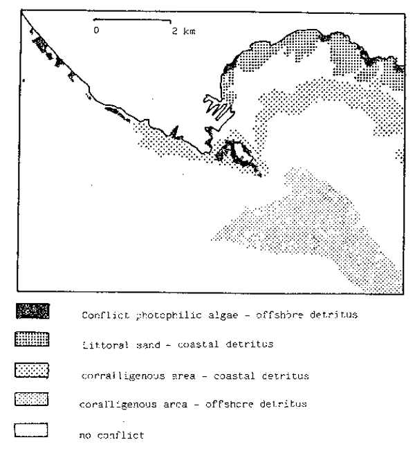
Figure 9.15 Map Showing the Greatest Conflicts Between Mapping Themes for an Area Near to La Ciotat, southern France
Introduction/Objectives
This paper re-examines recent trends in fish landings in the Mediterranean and Black sea basins, for each GFCM area, and compares estimates of production in the different basins using a measurement index of fish productivity in tonnes per surface area of continental shelf. There was a general consensus that, by the mid 1980's, fishing effort in the Mediterranean was excessive and that no significant gains in yield would result from increases in fishing effort. Thus, apart from some deep water resources, demersal stocks were seen as being exploited up to their maximum sustainable yield (MSY). Despite these contentions, subsequent increases in landings have occurred, in some cases at 100% above previous recent levels. An explanation for this was sought, and it was suggested that actual natural biomass production may be higher, i.e. due to increased nutrient enrichment from surface run-off via rivers. This was especially the case in the northern Mediterranean where human activity was much greater. This study is an attempt to use GIS approach to assess productivity in the Mediterranean, i.e. by examining trends in landings, spatial productivity variations and by establishing the best methods of comparing production in different basin areas.
Methods/Equipment
There were several essential sets of data which needed to be obtained. These included:
(a) Productivity per unit area for the shelf areas of the Mediterranean.
(b) Measurements of fish landings for all of the General Fisheries Council for the Mediterranean (GFCM) statistical areas during the last ten years.
(c) Maps of the shelf areas, and of the GFCM statistical areas.
Sources for this data included:
(a) The ETOPO5 database (US National Geophysical Data Center) of topography and bathymetry.
(b) A map of the FAO statistical divisions of the Mediterranean and Black seas.
(c) A map of the coastal state boundaries.
(d) A map showing fishing intensity in the western Mediterranean.
(e) Landings statistics covering coastal pelagic and demersal fishes, including crustaceans and molluscs, for GFCM Area 37.
The GIS software used in this study was ARC/INFO and ERDAS GIS, running on a VAX 3400 micro-computer.
Results/Discussion/Conclusions
The authors produce several fisheries productivity maps covering the Mediterranean and Black sea regions. Figure 9.16 is one example, it giving a clear indication of catch variations in the shelf areas. In interpreting any of the maps produced, it must be borne in mind that the statistical areas used were very large, so only generalised comments could be made. Total fish production appears to be much higher in the northern Mediterranean, and the authors contend that this is due to high nutrient inflows in the north, plus only modest levels of fishing in the south. The production in some areas could have been distorted by factors such as there being mainly anadromous or freshwater species, e.g. the Sea of Azov. Pelagics appear to be particularly productive in northern sea basins such as the Adriatic and Black Seas and the Sea of Marmara. Areas of the Mediterranean which are distant from nutrient sources certainly appear to have low productivity rates. These include Sardinia, the Levant and much of the north African coast. Demersal and shellfish landings are particularly high in the Gulf of Lions and Sea of Marmara where nutrient inputs from river and land run-off would be high. The authors conclude that these increased levels of productivity are interesting and are worthy of a more detailed study at the sub-regional level, i.e. with a view to either proving their hypothesis relating to nutrient inputs and their effects, or to allow new hypotheses to be formulated.
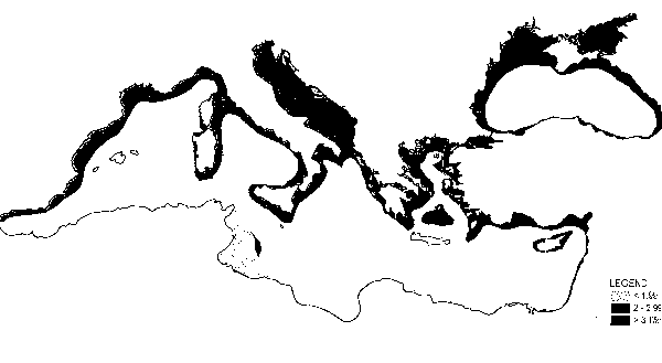
Figure 9.16 Total Catch of Pelagic and Demersal Fishes for 1989 from all Shelf Areas of the Mediterranean
| TITLE: | “Torres Strait Marine Geographic Information System”. |
| AUTHORS: | Long, B., Skewes, T. and Poiner, I. |
| PUBLICATION AND DATE: | Recent Advances in Marine Science and Technology '94. (Eds. O. Bellwood, H. Choat and N. Saxena) (1994b). Pacon International, Hawaii, USA. pp231–239. |
Introduction/Objectives
The Torres Strait is a shallow marine shelf area which links the Coral Sea in the east to the Arafura Sea in the west, Papua New Guinea to the north and Queensland, Australia to the south. It has a complex bathymetry, and there are over 700 reefs, shoals, and some 300 islands, most of which are remnants of hill tops which were once part of the land bridge from Australia to New Guinea. A diverse resource management structure has evolved in the area, involving the division of the marine shelf into zones which are variously managed by the Queensland State, the Australian Commonwealth and the Government of Papua New Guinea.
Methods/Equipment
In order to help with this management a Torres Strait GIS was set up in 1993, which is managed by the Australian Fisheries Management Authority (AFMA) from both Canberra and Thursday Island. A variety of ways and sources were used to acquire data for the GIS, ranging from purchasing digital datasets, to in house digitising and the entry of geo-referenced research data from various reports. Table 9.4 shows the data sets which were held by 1994. The base maps were digitised from 1:100 000 topographic charts of the Torres Strait. A number of GIS techniques were used to create area maps for some of the continuous variables, e.g. seagrass, sediment type and bathymetry. The software used was SPANS GIS, running on a PC and using the OS/2 operating system.
Results/Discussion/Conclusions
The Torres Strait GIS has been used to produce a large array of maps covering many topics. In their paper the authors give details on two of these:
(a) Seagrass Dieback Survey. The objectives of this survey were to quantify and assess the magnitude and extent of a reported seagrass decline in the north-western Torres Strait, i.e. by comparing data gained between 1984–1989 to data gained in 1993. Data on the present distribution of seagrass was gained by SCUBA divers who visually quantified estimates of seagrass ground cover at 251 sampling sites randomly spread throughout the 4743 km² study area. A GPS was used to determine geo-reference points. Data was also gathered on substratum, epibenthos, water visibility (m) and water depth (m). Maps were produced which showed the historical distribution (Figure 9.17a) and the present distribution (Figure 9.17b) of seagrass, and from these it was possible to construct a third map (Figure 9.18) which showed the extent of the changes in seagrass distribution. Figure 9.18 was constructed using the triangulated irregular network (TIN) algorithm within SPANS GIS. The authors cautioned that, although it was obvious that major changes had occurred, the interpretation of the maps should proceed cautiously in view of the reliability level of the data and the methods used. At least the basis had been provided for management decisions on what to do about seagrass dieback.
(b) A dugong sanctuary. The dugong population in the Torres Strait is the largest in Australia and possibly the world. These mammals are susceptible to overfishing because of their restricted stock and low reproductive rate. Additionally, they form an important dietary component for Torres Strait islanders. A dugong sanctuary has been formed in the western part of the Strait. The GIS has proved effective in showing whether dugong are currently dispersed in areas which offer the best habitats, and whether they are in areas which are least likely to be subject to human predation. In fact the GIS will allow for a means of modelling the complex interactions between biological factors, preferred habitats, physical factors, sociological factors, etc, thus allowing for the most effective dugong management plan to be implemented. It is clear from an inspection of Figure 9.19 that the dugong sanctuary area is not in the best location vis a vis their present distribution, i.e. one which accords more closely to the actual distribution of their seagrass food source.
| Description | Data Type | No. attrib. | No. records | Data Sources |
|---|---|---|---|---|---|
| 1. | Islander community information; population census demographics and traditional fishing catch data | point | 30 | 12 | Australian 1986 census data, Harris et al. (1994) |
| 2. | Water depth | point | 1 | >20,000 | Australian nautical charts: Aus 376, Aus 301, Aus 700, Aus 840, Aus 839, Aus 296, Aus 289, Aus 294, Aus 292, Aus 293, Aus 299, Various: pearlshell survey (Colgan and Reichelt, 1991), seagrass surveys (Long and Poiner, 1993), rock lobster surveys (Pitcher et al, 1992a) |
| 3. | Sediment grain size data | point | 7 | 251 | Various CSIRO cruises (Long and Poiner, 1993); University of Sydney reports (Harris, 1988) |
| 4. | Rock lobster (Panulirus ornatus) abundance | point | 4 | 370 | CSIRO rock lobster survey (Pitcher et al., 1992b) |
| 5. | Pearlshell (Pinctada maxima) abundance | point | 4 | 370 | CSIRO rock lobster survey (Pitcher et al., 1992b) |
| 6. | Epibenthos and bottom type descriptions | point | 4 | 370 | CSIRO rock lobster survey (Pitcher et al., 1992b) |
| 7. | Pearlshell (Pinctada maxima) abundance from pearl bed surveys | point | 6 | 67 | Colgan and Reichelt (1991) |
| 8. | Trochus (T. niloticus) abundance (Bourke Isles, eastern Torres Strait) | point | 1 | 80 | CSIRO trochus survey (Long et al., 1993) |
| 9. | Reef slope bottom cover (%) | point | 4 | 80 | CSIRO trochus survey (Long et al., 1993) |
| 10. | Seagrass presence/absence data | point | 1 | 1020 | Various CSIRO cruises (Long and Poiner, 1993; Pitcher et al., 1992a; Poiner and Harris, 1993) |
| 11. | Seagrass quantitative data: seagrass and algae species, no shoots/m, above and below ground biomass | point | 34 | 2600 | Various CSIRO cruises (Long and Poiner, 1993) |
| 12. | Dugong abundance: aerial survey | point | 1 | 380 | Marsh and Saalfeld (1991) |
| 13. | Trawl species catch abundance and weight | point | 16 | 80 | Poiner and Harris (1993) |
| 14. | Prawn log-book catch data | point | 16 | Queensland DPI (C. Turnbull) | |
| 15. | Shipping lanes through Torres Strait | line | 2 | 2 | digitised from nautical charts |
| 16. | Australian and Papua New Guinea mainland | area | 3 | 2 | digitised from 1:100,000 topographic maps |
| 17. | Torres Strait islands | area | 3 | >300 | digitised from 1:100,000 topographic maps |
| 18. | Torres Strait reefs | area | 3 | >700 | digitised from 1:100,000 topographic maps |
| 19. | Dugong sanctuary | area | 3 | 1 | Johannes and MacFarlane (1991) |
| 20. | Islander marine tenures | area | 3 | 9 | Johannes and MacFarlane (1991) |
| 21. | Area of the prawn fishery | area | 3 | 1 | Queensland Government gazette |
| 22. | Permanent closure of the prawn fishery | area | 3 | 1 | Queensland Government gazette |
| 23. | Exclusion area of prawn fishery for reporting purposes | area | 3 | 1 | Queensland Government gazette |
| 24. | Area of the tropical rock lobster fishery | area | 3 | 1 | Commonwealth Government gazette |
| 25. | Area for the pearl shell fishery | area | 3 | 1 | Commonwealth Government gazette |
| 26. | Area for the turtle fishery | area | 3 | 1 | Commonwealth Government gazette |
| 27. | Area for the dugong fishery | area | 3 | 1 | Commonwealth Government gazette |
| 28. | Area of the Spanish mackerel fishery | area | 3 | 1 | Commonwealth Government gazette |
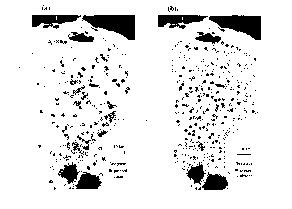
Figure 9.17 Seagrass Presence or Absence Data in Torres Strait from (a) the Historical Survey (1984/89) and (b) the 1993 Survey
| TITLE: | “Development of an Integrated Marine Geographic Information System.” |
| AUTHORS: | Li, R. and Saxena, N.K. |
| PUBLICATION AND DATE: | J. of Marine Geodesy. 1993. Vol.16. pp293–307. |
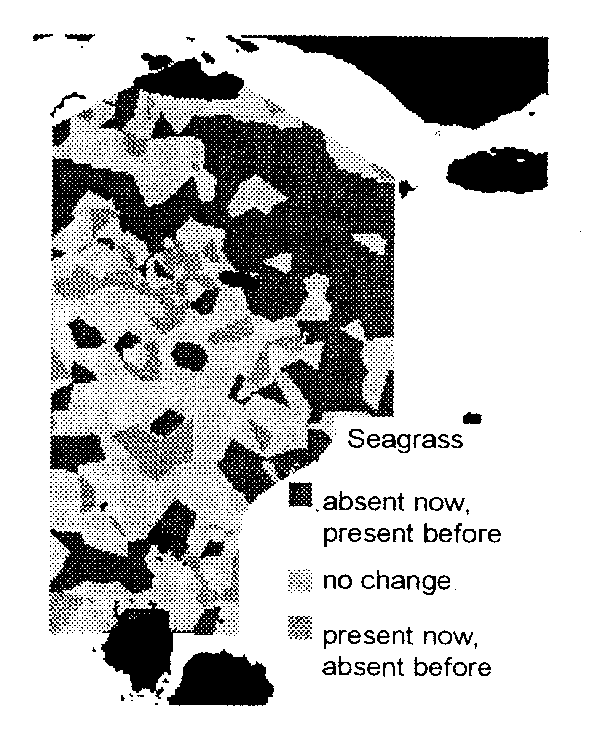
Figure 9.18 Changes in Seagrass Distribution in Torres Strait Between 1984/89 and 1993
Introduction/Objectives
The authors commence their study with a review of the increasing range of topics to which digital marine acoustic data is now being applied, e.g. in the fields of not only bathymetric mapping but also in the interpretation of sea bed types, sediment movement analysis, resource assessment, pipeline and cable routing and other geophysical and oceanographic work. To help in this applications work, the Pacific Mapping Center, at the University of Hawaii, have developed a marine GIS (MGIS) which has a large range of capabilities, only some of which can be examined in this case study. The essential feature that makes the MGIS different from the usual GIS is that the MGIS should be able to integrate side-scan sonar digital data in a similar way that a GIS can integrate RS data. The main purposes for developing their MGSI was as an aid in the selection of deep water research sites, for the generation of a 3-D database for navigation, to simulate underwater operations of a submarine research vehicle and for the production of mapping data.
Methods/Equipment
In designing the MGIS, the authors took into account the following main points:
a) The hardware configuration should be an open system for installing most relevant popular software.
b) Various software packages should be capable of being integrated into the MGIS.
c) The system should be easily capable of expansion.
d) 3-D data structures and modeling functionalities should be included for the simulation and animation of marine operations.
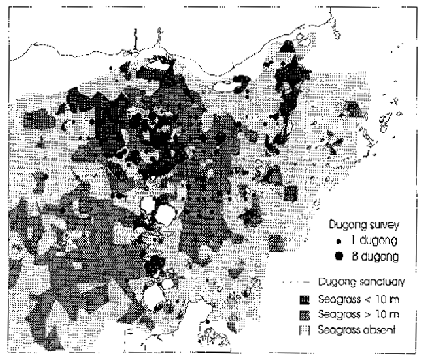
Figure 9.19 Seagrass and Dugong Distribution in the Torres Strait Plus Location of the Dugong Sanctuary
The MGIS hardware configuration which was set up at the University of Hawaii (Figure 9.20) is fairly comprehensive. Its main features are:
(i) Two work stations and two PC's running three operating systems.
(ii) A GRINNEL image processing system to handle the digital sonar image processing.
(iii) Connections via an Ethernet to other computer components on the campus.
(iv) A Silicon Graphics Iris workstation for animation purposes.
(v) Connections via Internet to off campus sites.
(vi) An array of peripherals including monitors, tape storage and drives, plotters, scanners, printers, etc.
(vii) A VAX work station to handle a variety of image and data processing functions. To make the handling of these as user friendly as possible, a task oriented menu has been constructed.
(viii) S SUN SPARC workstation having ARC/INFO installed plus programmes for format conversions and data integration.
Obviously, other systems are available for integration into the MGIS since the basic configuration as shown (Figure 9.20) is connected to other parts of the campus.
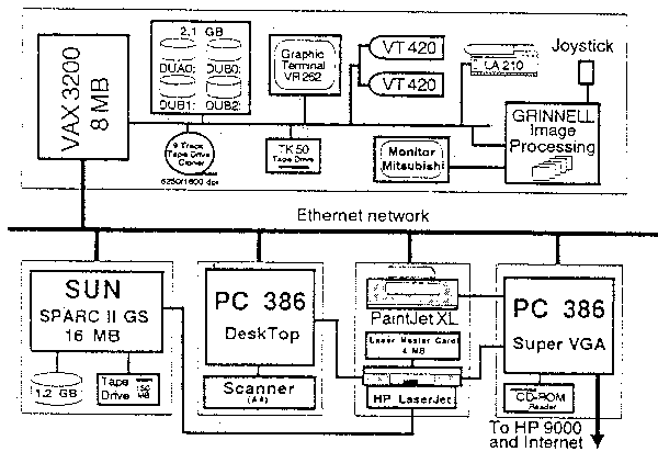
Figure 9.20 Hardware Configuration of the Marine Geographic Information System at the University of Hawaii
Since there is such a variety of potential data which could be integrated by the MGIS, the authors describe the main categories of spatially referenced data which could be most useful. This includes bathymetric data acquired from single-beam or multibeam acoustic systems, or sea floor imagery acquired from either side scanning systems or from video equipment. Other data may be available from marine mining maps, marine seismic data, gravity data and magnetic data. Data on other parameters which are unrelated to bottom characteristics could also be integrated into the MGIS, e.g. sea surface temperature data, wave height data and any data relating to spatial distributions at the surface.
The authors describe in some detail the methods used to select a deep-water marine research site. The idea was to find a site having a flat bed, which was as close as possible to a shore base, and which could therefore be conveniently used for underwater research experiments and developments. A 3-D bathymetric model was developed (Figure 9.21) using two series of previously acquired multibeam bathymetric data as surveyed by NOAA. These data were used to calculate parameters relating to both x and y directions and to depths. This allowed slope angles to be calculated. A small area to the south west of Hawaii was eventually found as being best suited to the search criteria.
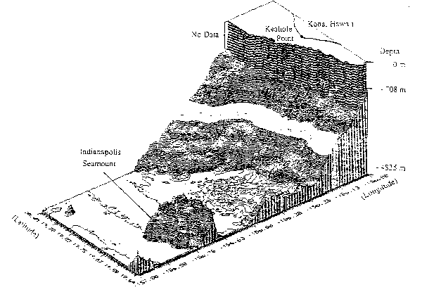
Figure 9.21 Display of Contours in the Selected Deep Water Site Off the Island of Hawaii
Results/Discussion/Conclusions
Once any bathymetric model has been obtained using the MGIS, then it is possible to view it from any direction, to zoom in or out, to colour code different depths and, if the requisite sonar imagery is available, then it is possible to drape the 3-D model with either geological information or perhaps with sediment type information. Further types of analyses are also being envisaged. Thus the authors note that “An analysis of layers of bathymetry, magnetic data, sonar images, and temperature gradients in areas with a high fishing productivity can help in understanding the relationship between fish habitats and the corresponding marine environment, This may improve our capability to balance between protecting marine species and increasing and maintaining fishing productivity.” (p.302).
| TITLE: | “Environmental Risk Analysis of Salvaging the Irving Whale.” |
| AUTHORS: | Collins, N. and Hurlbut, S. |
| PUBLICATION AND DATE: | Paper Presented at GIS93; March 23–25, 1993, Ottawa, Canada. |
Introduction/Objectives
On September 7th, 1970 an oil barge carrying some 4270 tonnes of Bunker C oil, sank in the Gulf of St. Lawrence, Canada. At the time only a small amount of the oil escaped, since it was of a type which increasingly solidifies in colder water, and the temperature at the 70 metre depth of the vessel was only just above freezing. Over the two weeks following the sinking, the leaked solidified oil was carried by prevailing winds along the paths shown in Figure 9.22. By September 21st, some 200 tonnes of oil was polluting 32 kilometres of shoreline on the Iles de la Madeleine, and a small amount was found on the shores of Cape Breton Island. Since the oil becomes solidified it is fairly easily disposed of, though it does have a high nuisance value, especially since small amounts are continuing, some 20 years later, to leak from the barge.
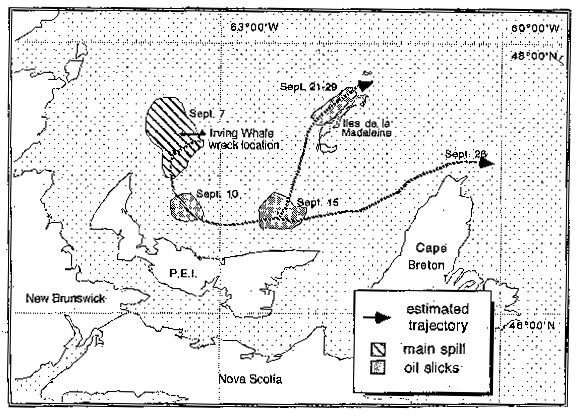
Figure 9.22 Estimated Oil Trajectories from the Oil Spill Coming from the Irving Whale in the Gulf of St. Lawrence
In response to public concern the authorities have initiated studies of salvage options, including the environmental risks involved. Most concern has come from the fishing community on Prince Edward Island, since they consider it likely that the remaining 3100 tonnes on board will pose a threat to their livelihoods for many years to come. A consortium of companies has now reviewed and reported on:
(a) The information surrounding the initial sinking of the barge and the subsequent impacts of continued oil leakage.
(b) The major resources vulnerable to a spill from any of the remaining oil.
(c) The marine and shoreline areas most likely to be oiled.
(d) The magnitude of the impacts anticipated. GIS methods have been used to help in these reports.
Methods/Equipment
Obtaining the data concerning the distributions of some of the variables which needed to be mapped as part of this study was relatively easy, e.g. data on recreational areas, seal colonies and sea bird distributions, but data concerning fish distributions and fishery areas was not so well documented, and it was liable to temporal variations. A major task then was to identify off- shore fishing areas and to establish up-to-date patterns of fishing activity. Information on these were used in the GIS so as to describe the relative importance of different offshore areas to surrounding communities. The GIS software used was “Atlas Pro for the Macintosh”. Once the GIS had been used to establish the distribution of fishing activity, the data was transferred to OILMAP, an oil spill modelling application to provide a single resource sensitivity and trajectory modelling database. Further details on both of these software packages are given in the source document.
Details on fish catches for all of 1991 were obtained from both fishing vessel logs and from purchase slips documenting the type and volume of fish sold to commercial buyers. Records of all fishing vessel logs, which includes geo-referenced catch locations, are kept at the Statistical District for Fisheries and Oceans Canada (DFO) in Moncton, New Brunswick, and details on landings are kept by the Bedford Institute of Oceanography (BIO) in Dartmouth, Nova Scotia. Data from the DFO was obtained on a 9-track digital tape, and the authors explain in detail how the catch data was transformed via a specially written Fortran programme so that it was in a suitable format for use by the GIS. A summary file of total catch by species group for each unit area by Statistical District was produced and downloaded to a Macintosh computer. The digitised boundaries of all the fisheries areas (and the coastline) were loaded to the GIS, and it was then a simple task to produce output such as that shown in Figure 9.23. Similar maps for all the Gulf of St. Lawrence fisheries were compiled, both by total catches, by species and by season.
Results/Discussion/Conclusions
The final analysis indicated that all demersal fisheries were concentrated in similar areas regardless of species. These areas were not within the zones of high risk from further oil leakages from the Irving Whale. Similarly, the semi-pelagic redfish and shrimp fisheries were also concentrated into areas where the risk was minimal. The authors conclude by noting that the availability of geo-referenced data was invaluable to this study, though they suggest ways in which data recording could be further improved, e.g. by having translation capabilities for converting different geo-referencing procedures. Also, it is essential that a greater awareness is made of the data bases that exist as potential input sources to any GIS.
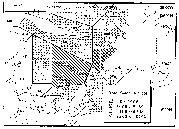
Figure 9.23 The Origins of all Catches Landed on Iles de la Madeleine During 1991
| TITLE: | “Protecting Irish Interests: GIS on Patrol”. |
| AUTHORS: | Pollitt, M. |
| PUBLICATION AND DATE: | GIS Europe. (1994) Vol.3, No.6. pp18–20. |
Introduction/Objectives
With the extension of Ireland's exclusive fishing zone to 200 miles in 1976, it meant that the country assumed responsibility for controlling fishing activities in 137 000 square miles of relatively rich fishing grounds. Most of the fishery patrol activities are carried out by the Irish Navy using seven ships plus some helicopters. Faced with an increased work load, fishery protection work is now being computerised, with the introduction of relational databases, expert systems and a GIS. A fully integrated Fishery Protection Information System (FPIS) has been set up which provides officers with operational information, and a fishery protection database records details of all fishing vessels operating in Irish waters.
Methods/Equipment
Each fisheries patrol vessel is equipped with a UNIX server, local area network and PC's. Databases are regularly updated from land to ship using satellite communications. Each fishery protection vessel must have access to complex and up-to-date fishery law. A PC-based expert system was developed to standardise the Navy's knowledge and enforcement of fisheries legislation. This contains a library of fisheries law alongside a “knowledge base” of common implementation rules. Before 1992 there was no way of achieving visual output from the FPIS so, in order to relate text based information to actual locations, to plan where patrols ought to be looking at fishing trends, and to allow all fishing activity, trends and incidents to be viewed, a GIS was introduced.
The GIS development, based on ARC/INFO, was instigated at the Naval Computer Centre in Cork, Ireland. The graphical side is based on digital displays of navigational charts. The Irish straight baseline 3, 6, 12 and 200 mile fishing limits, as well as the limits in nearby countries, have been superimposed on the charts. Other attributes added to the system include the ICES grid system, the Irish Box, disputed fishing limits, spawning grounds, fishing rights, underwater cables and pipelines, offshore platforms, low tide lines, navigation aids and submarine exercise areas. Figure 9.24 gives an example of GIS output, showing which countries (colour coded) have rights to fish for certain species within the 6–12 mile fishery zone.
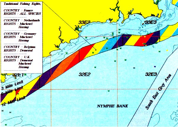
Figure 9.24 Example Output from the Irish Navy's Fishery Protection GIS Showing Fishing Rights of Neighbouring Countries
Results/Discussion/Conclusions
The system has been operational since December, 1992. In the fisheries protection headquarters all GIS output can be visually displayed on a chart wall so that briefing sessions can be run. Any part of the huge fishery area can be zoomed into and any reported fishing activity can then be reviewed. The location of all vessels can be displayed as colour coded icons. Interactive querying can be accommodated with the user selecting activities of interest from a set of predefined attributes, e.g. by nationality, fish species, vessel type, method of fishing, licence information, etc.
According to the people entrusted with using the system it is both very useful and highly efficient. It allows for the optimum allocation of scarce resources. It also allows for a careful check to be made on vessels which have in the past made infringements. In the near future it is planned that the GIS capability should be installed on each individual patrol vessel. It is also anticipated that extra duties will be able to be incorporated within the same overall system, e.g. pollution control and monitoring, search and rescue operations and any real time tracking. Eventually a total coastal management concept is envisaged, including the tracking of all sea- going activities.
| TITLE: | “Note on the Sediments and Hydrology of the Gulf of Carpentaria, Australia.” |
| AUTHORS: | Somers, I.F. and Long, B.G. |
| PUBLICATION AND DATE: | Australian J. of Marine and Freshwater Research. (1994) Vol.45, pp283–291. |
Introduction/Objectives
The Gulf of Carpentaria is a large embayment on the north east of Australia's coastline. It has an area of over 500 000 km² and a maximum depth of only 70 metres. The region has a monsoon climate with rainfall occurring mainly between December and March. The Gulf supports several important fisheries including one for penaeid prawns and a developing trawl fishery for teleosts. In November-December 1990, the Commonwealth Scientific and Industrial Research Organisation (CSIRO), Division of Fisheries, conducted a gulf-wide research cruise in waters mainly deeper than 20 metres. The main objectives of the cruise were to describe the size and distributions of fish resources, though information on sediments and water properties was also collected, i.e. to help in understanding the reasons for species distributions. This paper only describes results relative to hydrographic and climatic data.
Methods/Equipment
Figure 9.25 shows several features of the survey:
(a) The open circles show the locations of the main sampling points. These were established on a systematic grid, with a distance of 30 nautical miles between points, which themselves were fixed using a global positioning system.
(b) The land based open squares show the location of four Australian Meteorological Stations from where climatological data was obtained. Thus information on rainfall, temperature, wind speed and direction and atmospheric pressure was collected for the period 1968 to 1991, and were collated to monthly means.
(c) The line marked “T” shows a transect used to describe a north–south profile of the gulf.
(d) The solid black circles show additional sediment sampling points. Sediment data from these points had been collected opportunistically by another research vessel, plus other assorted means. The authors provide details on how the sediments were sorted by different granular fractions.
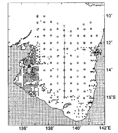
Figure 9.25 The Main Features of a Gulf of Carpentaria Marine Survey (see text for details)
Temperature and salinity data were recorded at each main survey point using a Yeo-Kal Model 606 data logger. Surface, mid-water and bottom water were samples were taken in order to measure turbidity. Having gathered all the data, spatial analyses were performed using SPANS GIS software running on a PC, with the main maps being derived from using the interpolation functions to derive sediment and water temperature “contours”.
Results/Discussion/Conclusions
The authors showed the results from the climatological data collection, but we need not discuss these further. Surface water temperatures showed very little horizontal stratification throughout the Gulf. However, there was a striking vertical stratification in deeper waters, and this difference between surface and bottom temperatures can be seen in Figure 9.26. Salinity showed no vertical stratification and only slight horizontal stratification. Turbidity was generally very low throughout the Gulf. Sediments were almost exclusively of mud and sand, with less than 6% of samples having a gravel content of more than 20%. Conditions generally became “muddier” from south-east towards the north–west. Muds were also very noticeable around sheltered embayments and river outlets.
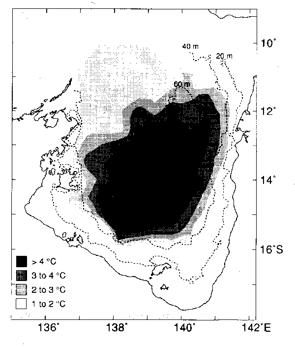
Figure 9.26 Differences Between Surface and Bottom Water Temperatures in the Gulf of Carpentaria, Nov/Dec 1990
The authors conclude by noting the importance of understanding the relationships between the various physical parameters measured and the productivity and distribution of the marine fauna. They show the speculation which has gone on over the evolution of the Gulf, and point out that since it must be a relatively new marine feature, then processes of faunal colonisation will still be occurring. It is speculated that the strong vertical temperature gradient in the central Gulf results from its depth and sheltered position, and that sediment accumulations of finer particles in the north west areas are largely the result of the clockwise current circulation. In the Gulf there is a strong link between sediment texture and the biomass and species diversity of benthic organisms, with abundance and diversity being much higher in the south-east where sediments were generally coarser. In fact, sediment grain size, together with depth, was found to explain most of the spatial variation in abundance of the various commercial penaeids in the Gulf.
| TITLE: | “Ecological and Oceanographic Relationships in the Southern Ocean” |
| AUTHORS: | Trathan, P., Murphy, E., Symon, C. and Rodhouse, P. |
| PUBLICATION AND DATE: | GIS Europe. (1993) Vol.2, No.6. pp34–36. |
Introduction/Objectives
The marine Life Science Division of the British Antarctic Survey (BAS) has been gathering data for the past 15 years relating to various oceanographic and biological processes which occur within the Southern Ocean ecosystems. Most of the data has been gathered from shipboard surveys, but increasingly satellite data is also being obtained. The use of satellite data is proving to help in the analysis of large scale environmental processes operating in the area. The use of GIS has only recently commenced as a tool for integrating the various data types. The main focus for the research effort has been the Scotia Sea, whose location is shown in Figure 9.27. This area is the site for some major fisheries, especially for Antarctic Krill (Euphausia superba).
Methods/Equipment
To fully appreciate the interactions between physical and biological components in the Southern Ocean area, it is necessary to collect data at a number of temporal and spatial scales. At the micro scale, which may be measured in square metres and minutes, work is being carried out on processes such as the grazing rates of zoo-plankton communities. At the meso scale activity includes the investigation of relationships between plankton concentrations and gyres, upwellings or ocean fronts. By contrast, at the macro scale, which may cover thousands of kilometers and several years, studies are being made on variations in the ice fronts or ocean current positions. GIS is gradually being introduced at all scales, and for many studies its scale independence is proving to be of great value.
Much of the data required is already in existence. Coastline data has been digitised and bathymetric digital data is available as part of the General Bathymetric Chart of the Oceans (GEBCO) and from research cruises undertaken by the BAS Geosciences Division. The main remotely sensed data being used at present are that on sea surface temperature and sea ice extent. This data is obtained from US National Oceanographic and Atmospheric Administration (NOAA) satellite images. These data are of use in inferring oceanographic conditions and in estimating the distribution of many Southern Ocean animals. Eventually it is proposed to use ocean colour satellite data. Biological data comes mainly from fisheries and other surveys indicating distributions and abundance. Some information has recently been obtained from monitored tagging experiments. Catch rates and location data are available for all exploited fish stocks in the Southern Ocean.
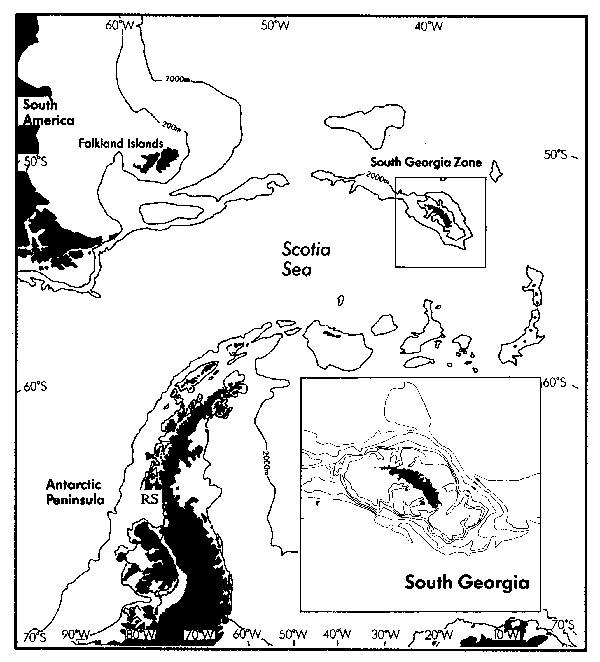
Figure 9.27 Location Map of the Scotia Sea Area, Including the South Georgia Island Area in Detail
Results/Discussion/Conclusions
At the present time most GIS work is being done on examining the relationship between physical parameters and the distribution of different species. Krill is being extensively studied because it is immediately available in the food chain to an array of higher predators. Figure 9.28 gives an indication of krill density along survey tracks in the large cell surrounding South Georgia (see Figure 9.27). Since it is known that krill biomass volumes are now very low, then it is important to be able to calculate both the causes and effects of this. Plans for the immediate future include gathering more detailed data on fin fish and squid distributions, as well as using satellite tracking methods to learn more on the disposition of seals and birds. Finally, the authors see this Southern Ocean GIS as being useful for establishing the causal links between oceanographic or meteorological phenomena and/or events occurring at one area, which prove to have a long term knock–on effect in other areas.
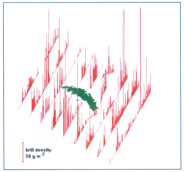
Figure 9.28 Krill Biomass Distribution in the South Georgia Area as Plotted by the British Antarctic Survey
| TITLE: | “An Efficient Method for Estimating Seagrass Biomass.” |
| AUTHORS: | Long, B.G., Skewes, T.D. and Poiner, I.R. |
| PUBLICATION AND DATE: | Aquatic Botany. (1994a). Vol.47. pp277–291. |
Introduction/Objectives
Seagrasses are an important component of coastal ecosystems. They provide nursery grounds, adult habitat and food for commercially important species, plus habitats for a range of marine birds and mammals. They also produce large amounts of detritus and dissolved organic matter. However, the traditional method for sampling seagrass, by taking cores and by quadrats and perhaps the use of scuba divers, is time consuming and expensive. This limits the amount of sampling which can be undertaken, which in turn can result in less reliable estimates. The authors have developed a sampling technique for seagrass biomass estimation which uses aerial photography, GIS and global positioning systems (GPS). A seagrass grab was also used. The area of study for the authors sampling survey covered 38 km² at the mouth of the Brisbane River in southern Queensland, Australia.
Methods/Equipment
A digital outline of part of the study was obtained from the Port of Brisbane Authority, and the rest of the study area was digitised from local 1:25 000 topographic maps. The digital outlines were input into a PC version of SPANS GIS. Figure 9.29 shows the study area used plus the location of seagrass sampling points. Using an aerial photograph of the study area, taken at low tide from a height of 3 000 metres, six seagrass and one subtidal (channel) strata were identified. The outlines of these areas were also digitised for entry to the GIS, and Figure 9.30 shows the various classifications. The GIS was then used to both calculate the area of each of the seven strata, and as a basis upon which to divide up the area so that random seagrass sampling points could be located.
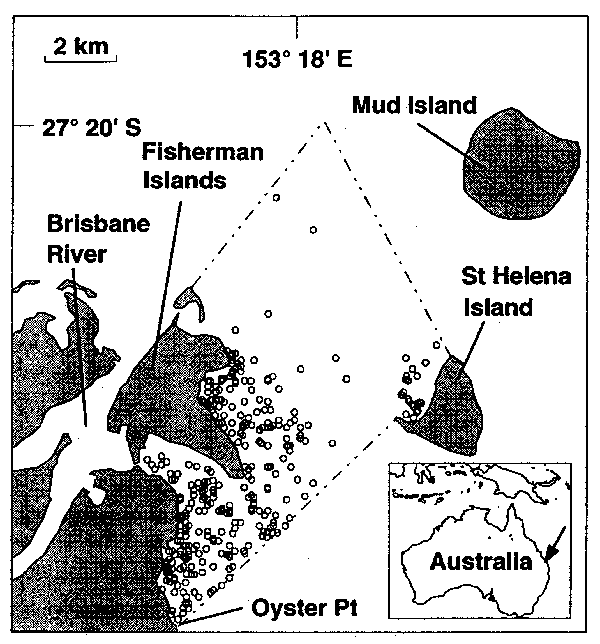
Figure 9.29 Map of the Seagrass Sampling Area in Moreton Bay, Queensland Showing Distribution of Sampling Points.
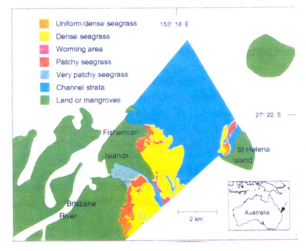
Figure 9.30 The Classification of Various Seagrass Strata in Part of Moreton Bay, Queensland
In the field the selected sampling points were detected using the GPS. At each site a sample of the bottom was taken using a hand operated seagrass grab. The authors detail the specifications of the grab and how it was used. The contents of each “grabbed” sample was sorted (at sea in a dinghy), with the seagrass and rhizomes (roots) being removed for later sorting by species, drying and weighing. A record was made at each sampling point of the sediment texture. The authors were careful to standardise the seagrass grabbing techniques, i.e. so that differences in results could not be caused by differences in the digging efficiency of the grab working in different types of bottom conditions. A detailed description was also given on how the authors worked out where best, among and between, the seven strata their sampling efforts should be directed (based on a Neymann allocation model), on the optimum number of grabs which should be taken per site from a cost-effective viewpoint, and on how many samples would be required. Thus they estimated that a total of 361 samples were needed to be within a precision of 15%.
Results/Discussion/Conclusions
Four types of seagrass were found in the study area. The distribution of these was a reflection of the varying conditions found, with water depth being the main determinant. There was a strong correlation between the above and below ground seagrass biomass density, though the proportions of biomass above or below ground varied between the species. There was no seagrass in the so-called “channel” stratum, whilst the highest amount was found in the St. Helena stratum (80%). The authors provide several detailed tables showing various parameters relative to seagrass distribution and density.
The study showed that cost-effective, accurate and reliable seagrass biomass estimates for the study area could be achieved by using the combination of aerial photograph, GIS, GPS and the seagrass grab. Stratification of the study area substantially improved the precision of the estimate compared with a simple random sample. The grab proved an easier method of obtaining samples than the traditional coring method, though some modification to its design is necessary unless some allowance is still to be made for variations in bottom type (and thus grab penetration). The authors also found that, whereas many traditional studies of seagrass biomass had relied upon counting the numbers of shoots to obtain a measure of density, a reliable estimate could be found by simply weighing the biomass.
| TITLE: | “A simulated GIS exercise to demonstrate its usefulness in the management of Senegalese demersal fisheries.” |
| AUTHORS: | FAO-CRODT-ORSTOM. |
| PUBLICATION AND DATE: | Report of the Training Course on the Application of GIS to Fisheries. FAO Project GCP/RAF/288/FRA. (Rabat, Morocco; 3–14 April, 1995) |
Introduction/Objectives
To achieve a sustainable fisheries sector in West African waters, it will be necessary to improve the range and quality of information which is available to fisheries management in order to ensure effective decision making. As one means of achieving this, a regional GIS for coastal and oceanic marine fisheries is being established for West Africa, as a collaborative venture between FAO and the respective governments. This covers most West African maritime countries. The establishment of this GIS will involve not only the training of personnel in the practical use of GIS, but also in creating an awareness amongst the decision-makers as to the potential which GIS can offer for management and development planning. Although the GIS will eventually operate at a variety of scales ranging from local to international, it will be initially important to develop fisheries resources GIS's at a national level. The reasons for this are mainly concerned with minimising problems associated with obtaining standardised data, with exchanging data and with creating a local impetus for the GIS to succeed.
As part of the promotion of the fisheries management GIS, a training course was organised by FAO, in collaboration with the Royal Centre for Remote Sensing (Rabat, Morocco), the Scientific Institute of Marine Fisheries (Casablanca), the Oceanographic Research Centre of Dakar-Thiaroye (CRODT)(Senegal), and the French Institute of Scientific Research for Development and Cooperation (ORSTOM)(France). This was held in Rabat, Morocco in April, 1995, and the main purpose was to introduce key personnel to the functionality and potential of GIS as an aid to fisheries management. As part of the training course, FAO together with CRODT and ORSTOM, developed a GIS simulation package whose aim was to both illustrate the main GIS concepts, methods and the results that can be achieved and to explain any functional constraints which the system has.
The simulation package consisted of three “case studies”:
(a) To show the relationship between the distribution of demersal fish resources in Senegal and factors relating to fish habitats.
(b) To show the seasonal conflicts which occur on a local scale during the May-June period between artisanal fishermen from Saint Louis, who are fishing for “sole” with gill-nets, and those from Kayar, who are fishing for “thiof” using hand lines.
(c) To show the increasing conflicts which are also occurring, though here at a national scale, between artisanal fishermen and the industrial fishing fleet.
The simulation package has not been written in great detail since it was only for demonstration purposes. Arising from the demonstration of each of the case studies, participants in the training course should be aware of the types of “on demand” mapping output which could be produced, the types of tabular data involved, and they should also have gained an appreciation of the amount of support which GIS can offer to those management problems having a spatial component.
Methods/Equipment
The simulation package was assembled at the FAO headquarters in Rome. To do this data had to be acquired from a number of sources including ORSTOM, the CRODT and UNEP. The data supplied was in a mixed format consisting of both paper and digital maps and tables. All work was done on PC's using four main software packages, i.e. FoxPro (as a database) and IDRISI, PC ArcView and ArcInfo (for the GIS graphical work). In assembling the material problems had to be overcome concerning different map scales, different coordinate systems, units of measurement, incorrect geo-references, missing data, types of data, etc. For demonstration purposes, the GIS output was assembled as a presentation display. Thus it was necessary to put together a computer based “presentation” consisting of a complete sequence of screen views which were specially selected to show how a GIS is assembled in order to carry out a particular task. FAO also prepared a manual which described textually the operations of each of the three case studies.
Results/Discussion/Conclusions
Although three case studies were presented at the training workshop, space precludes an illustration of all of these. Only the resulting presentation of case study (a) above is described in some detail. Figure 9.31 shows the sequence of maps which were displayed as a means ofshowing the relationship between fish resources and their habitats, and this sequence is now briefly described.
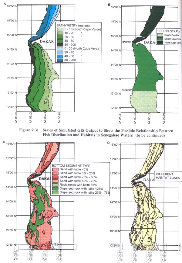
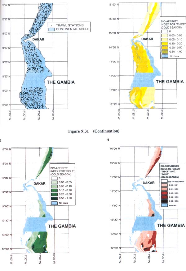
1. A bathymetric map using five class intervals was digitised using data from a series of 1:200 000 paper maps provided by ORSTOM. This covered the inshore Senegalese waters to a depth of 200 metres, i.e. to approximately co-incide with the continental shelf area (Figure 9.31a).
2. In the absence of sufficient data on bottom water temperatures, a “proxy” strata map was produced with the idea of showing how water temperatures were likely to change with latitudinal variation from north to south (Figure 9.31b).
3. Using the same data source as in 1 above, a bottom sediment type map was digitised. This effectively classified the shelf waters into seven classes each of which was differentiated by particle size and/or the degree of “rockiness” (Figure 9.31c).
4. The three maps described above were superimposed (overlayed) so as to produce a marine fish “Habitat” map for Senegal (Figure 9.31d). In carrying out this operation, the computer also generates a new attribute table which contains the details on all three maps. From a perusal of Figure 9.31d it can be seen that a large number of different habitat polygons have been produced, and it is possible to perform various calculations or analyses of these as required. No key has been shown on Figure 9.31d because of the large number of different classes, but the necessary information is stored in associated attribute tables.
5. In order to show the distribution of fish resources, it was necessary to use a Senegalese government database holding containing data on trawl surveys. The type of data which is relevant to this exercise included:
| Season 1 | cold season |
| Season 2 | warm season |
| Code | a code for the trawl station |
| Latitude | a geo-reference |
| Longitude | a geo-reference |
| Trawl | time duration of trawl |
| Species | names of species caught |
| Weight | for each species caught |
For ease and uniformity of use this data was transferred from its original ASCII file format into the database package called FoxPro.
6. Using this trawl survey data, it was simple to generate another map layer called “Trawl Stations” (Figure 9.31e). Here this is shown as the basic locations of the trawl stations, but it must be remembered that for each of these sites it would be possible to show the quantity of each species of fish caught, by warm or cold season if required.
7. By overlaying the trawl station sites onto the habitat map it was possible to determine the relationship between fish types and habitat, i.e. since fish types are recorded at all trawl station sites. Clearly it would be difficult to produce map output on this spatial relationship - this is mainly because of the large number of possible relationship classes. However, this overlay procedure was useful in that it produced a new attribute table listing the relationships, and this table provided the information for the next step, i.e. to produce a bio-affinity index. This represents an index showing the degree of relationship between a species and a habitat type.
8. The bio-affinity index was computed for each trawl station using the formula
where X = [log(1 + catch rate)]
An average species bio-affinity index was then computed for each season and for each polygon of the habitat coverage map.
9. Using the attributes contained in the bio-affinity index file, it was possible to link these to the habitat map coverage in order to produce a geographic representation of the bio-affinity index for each species and for either the warm or cold season. Figure 9.31f shows the bio- affinity index map for “thiof” in the cold season, and Figure 9.31g shows a similar map for the distribution of “sole”.
10. Finally it was possible to produce a map showing the co-occurrence between thiof and sole, i.e. by simply overlaying Figure 9.31f with 9.31g to produce 9.31h. Note that in the majority of the Senegalese continental area there was in fact little co-occurrence. This map should give the fisheries manager a fairly clear visual impression of habitat preferences for the main fishery species in Senegalese waters.
We have described here only one specific task which was used as part of the GIS training programme. The other two case studies detailed various other ways in which GIS might be useful. So, for instance, it would be a comparatively simple task for the GIS to use the trawl survey data to calculate an abundance index by species and by trawl station. This data could then form the basis of an interpolation mapping exercise to produce mean fish density maps for Senegalese waters by season and by species. A knowledge of fish density would greatly help in the allocation of fishing effort and in estimating the fishery resources available. A further way in which the GIS should prove most valuable is in mapping conflicts between fisheries and in estimating the effects of these resource conflicts. Thus GIS can allow for an estimation of resource depletion or of resource availability along the zones of conflict, and having an objective graphical representation of the results of the conflicts could prove invaluable in resolving disputes via mediation or arbitration. It would be anticipated that such maps could prove also help in instituting a managment regime whereby fishing boundaries were seen as non-static, i.e. being variable on a regularly negotiated basis.
| TITLE: | “Propositions d'usages de SIG en halieutiques” |
| AUTHORS: | Le Corre, G. |
| PUBLICATION AND DATE: | Etude et Séminaire sur les Systèmes d'Information Géographique (SIG) en Méditerranée. Vol.2. Commission des Communautés Européennes - Projet TR/MED/92/013. |
Introduction/Objectives
The French marine research institute, IFREMER, have a number of developments in progress which are aimed at using GIS as a research and/or management tool. One such project is based upon marine fishing in the Mediterranean Sea. This project's objective is to create a set of analytical tools and some “scientific spatio-temporal simulations” which will allow IFREMER to model the interactions between fishery activities and other uses of coastal and maritime space. As one approach to the development of a marine fisheries GIS, it was decided to first create a prototype fisheries GIS, i.e. before even defining the precise functions of the future GIS. This would allow for some of the development considerations to become more obvious. The author notes that, in order to enable a fisheries GIS to function satisfactorily, it was necessary to rely upon the skills of people from a diverse range of interests, e.g. biologists, demographers, legal people, data processors, etc. He also noted that the prototype GIS could best be assembled within a framework of the following three functional classes:- (i) representation, (ii) analysis and (iii) simulation.
Methods/Equipment
The prototype fisheries GIS given is displayed simply in the form of a presentation to show the characteristics and capabilities of the software, i.e. it does not show any of the scientific results which would hopefully be achieved by a fully constituted system. All GIS work has been done on a UNIX workstation using ARC/INFO version 6.1.2. Data has come from IFREMER sources. The author illustrates his GIS by showing two distinct so-called “presentational GIS modules”:
1. This first module is very much a simple representation of a so-called “library” of marine related data, with ideas being given as to how marine and fisheries related data could best be displayed.
2. The second module is a simulation which emphasises the potential for visualising complex fisheries situations and to interpret results from different input scenarios.
The database model upon which the graphics have been produced allows the map to be questioned according to several criteria:
(a) Spatial criteria, i.e. relative to distances, lengths, areas, etc. Selections of specific areas can be made by specifying sub-sets (windows) of the main area.
(b) Temporal criteria, i.e. changes over time can be evaluated using a so-called “ECHO” mechanism. This would allow the user, for instance, to select data for all the months of January and February between 1950 and 1980.
(c) Typological criteria, i.e. essentially questioning via a hierarchy of relevant themes.
Results/Discussions/Conclusions
Figure 9.32 is an example of output from the first presentational module. Here focus is made upon a small part of the Gulf of Lyons near Sete. Shown are bathymetric depth lines, isolines of distance from the coast, plus all the trawl haul tracks made over a particular time period. The screen image gives some indication of the various windowing possibilities and that a large range of display and data manipulation and analysis tools exist. Within most menu items there are sub- menus to allow for deeper questioning or analysis. Obviously the display could be variably zoomed, buffers could altered as required, time periods could be adjusted, etc. Once a desired screen image was obtained, the GIS functionality would allow for interrogation of the “visualized database”. So for instance, based on the information shown in Figure 9.32, it would be possible to ask - “How many trawl hauls were made in water of x depth between time y and time z ? A host of other questions could also be posed.
Figure 9.33 provides an example of output from the second “simulation” module. Here it can be seen the some of the “library” of data held on the Gulf of Lyons area has been portrayed in a slightly different map form, showing factors such as the coastline, bathymetry, buffer zones, etc. The green areas on the Figure represent all marine locations which can be reached within certain time limits, and where the water is less than a specified depth. This simulation could also be considerably extended, with the general idea that it would be an aid to fishery deployment in terms of activity distribution from certain ports.
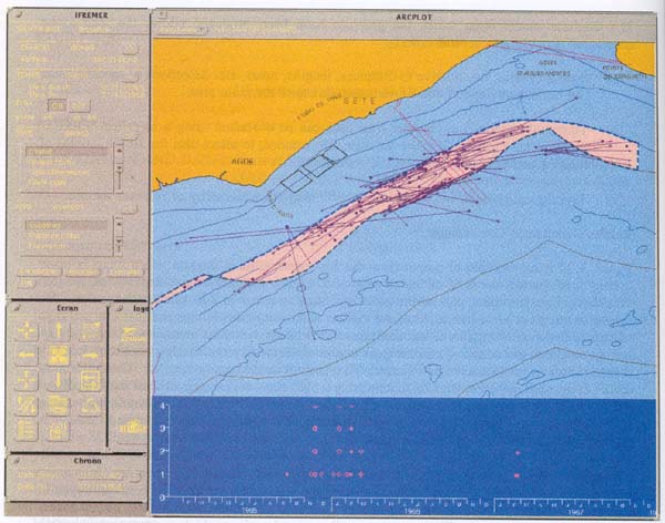
Figure 9.32 Screen From an IFREMER Development GIS Showing Trawl Haul Locations in the Gulf of Lyons, France
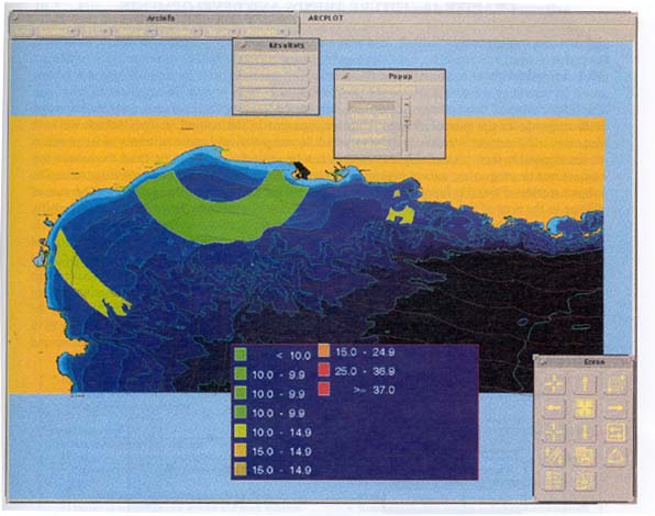
Figure 9.33 Screen From an IFREMER Developmental GIS Showing Simulated Fishing Activity Zones in the Gulf of Lyons, France