The preventive maintenance programme includes many sections, an essential one of which is the maintenance work done directly on the machine. It needs to be performed by skilled craftsmen and in this chapter an attempt is made to provide the engineering staff of milk plants with a guide to maintenance comprising:
Basic rules concerning safety at maintenance work
Essential information on hygiene requirements relating to milk plants
Diagnosis of faults
Examples of routine maintenance procedures
Regulations concerning health and safety at work may differ from country to country in detail, but some relevant provisions are embodied in all of them. All craftsmen must adhere strictly to the regulations concerning their particular trade, together with the Company rules complying with the country regulations actually in force. It is the duty of every employee while at work to take reasonable care for the health and safety of himself and of other persons, who may be affected by his acts or omissions at work. No person shall intentionally or recklessly interfere with or misuse anything provided in the interests of health, safety or welfare in pursuance of any of the relevant statutory provisions. Every craftsman must be trained to be safety conscious and should know the correct use of protective clothing.
Overalls should be buttoned up, sleeves rolled up above the elbows or cuffs buttoned up, and a protective cap should be worn, as illustrated in Fig. 12.
Gloves may not be worn at all times, but a suitable barrier cream should be used to protect the skin. Cotton gloves with reinforced non-slip gripping surfaces are worn when handling oil or grease covered components or materials. Heat-resistant gloves should be used to give protection against burns. Leather gloves give protection against sharp corners when handling bulky or heavy equipment. Rubber gloves are worn when using cleaning fluids and to protect the hands from skin damage due to air blast when cleaning components by means of compressed air.
Footwear worn should be reinforced safety shoes or boots with reinforced toecaps, especially at work demanding the lifting of relatively heavy components. Special care should be taken where the conditions underfoot are hazardous such as excessive water on the floor.
Goggles must be worn when a chisel, a sharpening tool or a grinder are used, and when cleaning with compressed air is performed.
Hazard warning signs, obligations and instructions should be widely displayed throughout the buildings on walls, vehicles, containers, etc. to bring these to the attention of personnel. The series of signs prepared by the British Standards Institute is shown in Figs. 13 A and B. These show the black triangle with a black-on-yellow pictogram indicating warning, the red circle with crossbar and a black-on-white pictogram denoting a prohibition and the blue circle with the pictogram imposed in white denoting obligation or instruction. A green square with the pictogram in white is for information.
Every potentially dangerous part of any machine whether power driven or not must be securely protected. Before work is started on a machine it is essential to ensure that it cannot be accidentally set in motion. The power supply system must be so disconnected that some special action is required for its reconnection. If the machine has individual drive, either the fuses should be removed with precautions to prevent accidental replacement, or the switch should be locked in the ‘off’ position. In some cases mechanical isolation might be necessary such as removal of belt from drive. A notice should be displayed at the machine to be worked upon to warn persons against any attempt to set the machine in motion. The power should be connected and the warning notices removed only by the maintenance craftsman after he has completed his work and made the necessary checks.
In exceptional circumstances it may be necessary to observe closely the machinery in motion with the guards removed. Such work may only be carried out by qualified persons, and only when permission to do so has been obtained from the supervisory officer on duty. Before a guard or fence is removed from machinery, warning notices should be displayed on all sides where there is access to the unguarded mechanism. Guards and fences should be replaced before the warning notices are withdrawn. This ‘permit-to-work’ system ensures the safety both of the craftsman and of the equipment on which he works. Certain tasks require an extra strict observance of safe working practices, e.g., when adjacent equipment may still be in use. Such tasks must not be carried out by a craftsman unless he has been issued with written authority to do so in the form of a signed ‘permit-to-work’. It is essential that the correct procedures are followed and are accepted as the normal method of working. The practices of a permit-to-work system vary according to local needs, but the contents of such a permit usually include the description of the work involved, the time limits between which the equipment or the area must be made safe, the title of the issuing authority, the officer-in-charge and the necessary precautions required to make the equipment safe to work. The permit must be signed by the officer-in-charge.
General safety rules should be displayed in places where they can be easily and frequently seen by the staff concerned. It is more effective to display them as a list of what should and what should not be done in connection with particular types of jobs. An example of this, referring to safety of electrical works, could be displayed as:
| DO | - report all electrical faults | DO NOT | - use defective cables, plugs, etc. |
| - keep loose cables off the floor | - connect power tools to lamp sockets | ||
| - keep all electrical equipment dry and clean | - attempt to repair electrical electrical equipment | ||
| - use compressed air carefully | - direct compressed air at yourself or others |
Hygienic working practices include precautions concerning personal hygiene, practices during maintenance operations and finally the CIP (clearing-in-place) system involving cleaning and sterilization of equipment after completing and/or before starting processing and manufacturing operations.
Personal hygiene includes medical clearance for working in food processing plants, which needs to be renewed at pre-determined intervals. Clean protective clothing must be worn, ‘no smoking’ notices observed and all tools and equipment must be carried in closed tool boxes or bags.
Hygiene precautions during maintenance operations must concentrate on preventing the food from begin contaminated by extraneous material. It is therefore essential that all fastening devices are secured firmly, and that only non-corrosive fixing parts such as washers or split pins are used when in direct contact with the product or passing above the product. Further precautions to be strictly adhered to are:
Oil grease, solvents and compounds used on food machinery must be those recommended for such use;
All electrical equipment must be correctly waterproofed;
Glass instruments such as thermometers must be properly encased, so that they remain in position if broken;
There must be no leakages of services, especially refrigerants and cleaning solutions;
Recycled water systems must be frequently trested;
Cleaning nozzles in washing devices must not be blocked or excessively worn;
Cold storage units must be adequately ventilated when not in use.
Once a maintenance task has been completed, all debris, tools and equipment must be removed and the plant left ready for cleaning and sterilizing operations.
Cleaning in place (CIP) consists of circulating water and various chemical solutions through assembled process equipment. In pipelines and other enclosed machines the solutions fill the equipment and each wash pushes out the previous solution. Control valves are used to control the critical operations of solution changes. It is of the utmost importance that the control valves are kept in faultless operating condition. Faults in control valve operation can become the source of serious damage to the products by contamination with detergents.
Skill in diagnosis involves the identification of the faults which arise in a machine or system, and the quick and accurate location of the cause of the faults. Not only should all the signs and symptoms that can indicate a fault and its cause be recognized, but also a suitable method of collecting this information should be adopted. An example of a six-step approach is illustrated in Fig. 14. A guide to fault finding is shown in Fig. 15. Whenever possible tests should be carried out to determine whether a series of components is working correctly before examining individual components. To reduce diagnosis time to a minimum the ‘half split’ approach to fault diagnosis should be used. For example, if there is no output from component E, by testing component C the area in which the fault could lie is halved. If C is functioning correctly, the next component to be tested would be D, as shown in Fig. 16.
Many machine manuals contain a section which includes fault finding or trouble shooting charts covering a number of known common faults. The information contained in these charts is based on previous experience. Predicted or anticipated faults may also be included, based on the knowledge and experience of the design engineer. The charts normally contain the fault, its cause and remedy. They are a useful aid to fault diagnosis, particularly in relation to product or process faults, and they should always be used.
Manuals for craftsmen engaged in any given industry usually contain a selection of servicing and maintenance instructions related to the equipment most often installed in the factories concerned. They are used in conjunction with handbooks and general instruction manuals on mechanical maintenance, whose contents cover the job knowledge required by a skilled fitter. In many developing countries such manuals may not be available in the mother-tongue of the craftsman. Moreover, those available may not be easily understood, or may not apply to the needs of a milk plant. In this section two examples are given of the type of information with which the maintenance crew should be provided during on-the-job training. Both are taken from the Instruction Manual for dairy industry fitters, by permission of the Dairy Trade Federation of the United Kingdom, and are illustrated in Figs. 17/18. These examples deal with securing and fixing devices, and bearings, and demonstrate the preparation of training aids and the conveyance of the instructions to the trainees. The efficiency of the training and subsequently the efficiency of the performance of the maintenance work is greatly improved when each trainee is provided with a carefully prepared manual. Such manual preparation may not be an easy task, but it is continuous work and after a few years a manual of valuable information can be made available if proper attention is given to the problem by the engineering department of the plant.
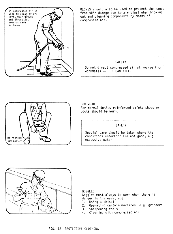
FIG. 12 PROTECTIVE CLOTHING
HAZARD WARNING SIGNS
For the safety of yourself and all other personnel any hazard warning signs displayed inside or in the vicinity of the factory should be observed. These signs may appear in areas, on walls, vehicles (tankers) or containers, e.g. drums.
The full range of these signs is illustrated in black and white only. Reference should be made to the appropriate British Standard full colour charts.

FIG. 13A HAZARD WARNING SIGNS IN UK

SAFETY COLOURS AND CONTRASTING COLOURS
| SAFETY COLOUR | MEANING OR PURPOSE | EXAMPLES OF USE | CONTRASTING COLOUR (if required) | SYMBOL COLOUR |
|---|---|---|---|---|
| Red* | Stop Prohibition | Stop signs Identification and colour of emergency shutdown devices Prohibition signs | White | Black |
| Yellow | Caution, risk of danger | Indication of hazards (fire, explosion, radiation, chemical, etc.) Warning signs Identification of thresholds, dangerous passages, obstacles | Black | Black |
| Blue | Mandatory action | Obligation to wear personal safety equipment Mandatory signs | White | White |
| Green | Safety condition | Identification of safety showers, first-aid posts and rescue points Emergency exit signs | White | White |
* Red is also used to identify fire fighting equipment and its location.
FIG. 13B HAZARD WARNING SIGNS AND SAFETY COLOURS IN UK
When commencing fault diagnosis do not start to strip down parts immediately, as this may destroy the evidence which will eventually lead to the cause of the fault, but apply a logical approach.
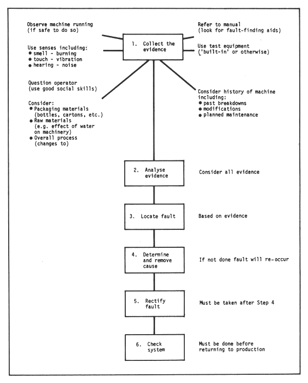
FIG. 14 SIX-STEP APPROACH TO DIAGNOSIS OF FAULTS
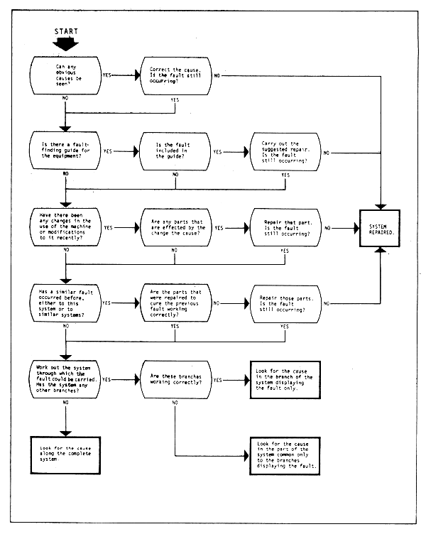
FIG. 15 GUIDE TO FAULT FINDING IN THE SYSTEM
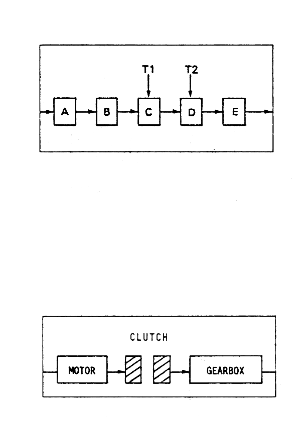
USING THE HALF-SPLIT APPROACH TO LOCATE THE CAUSE
Whenever possible, tests should be carried out to determine whether a series of components is working correctly before examining components individually. To reduce diagnosis is time to a minimum the half-split approach to fault diagnosis should be used.
For example, if there is no output from component E, by testing component C the area in which the fault could lie is halved. If C is functioning correctly the next component to be tested would be D.
Other considerations which should be taken into account when using this approach include accessibility of test points and the odds on a fault occurring in a particular component, i.e., if the odds on the fault lying in A are three times as great as for the other components the first component to be tested should be B.
CHECKING FUNCTIONS/COMPONENTS
When checking functions or components inputs and outputs should be considered.
For example: Input from motor to clutch correct. No output from clutch when engaged. Fault lies in clutch.
NOTE: The cause may be a tight or worn bearing in the gearbox. Adjusting the clutch could temporarily remove fault but it would eventually recur. Cause must be determined and removed.
FIG. 16 HALF-SPLIT APPROACH TO FAULT DIAGNOSIS
Securing and fixing devices. These include basically screws, nuts, washers and shims.
Screws are identified by the head type, length and the type of thread. The types of screw heads are shown in Fig. 17. The definition of the screw length is also shown in Fig. 17. The basic types of threads include metric, British Standard and self tapping. Except for self tapping types, screws are screwed into tapped holes or used with nuts. Blind holes should be checked to see that there is no swarf in the bottom of the hole and that the screw is not too long. The screw should be 1.5 mm shorter than the depth of the thread plus the thickness of the part being secured. The correct type of screwdriver must be used for fitting the screws. Fig. 17 illustrates the details of screws and their fitments.
Nuts are manufactured as standard and special purpose nuts. Standard hexagon nuts are used either singly with or without a locking washer, or as full nuts or as lock nuts to lock another nut into a fixed position on a thread. A lock nut is placed under the main nut and tightened. The main nut is run down on top of the lock nut and is tightened with one spanner, whilst a second spanner prevents the lock nut from turning as shown in Fig. 18. Special purpose nuts include castellated nuts for use with split pins, self-locking nuts with nylon inserts and spring steel self-locking fasteners. When using castellated nuts the bolt with nut must be assembled, a clearance hole drilled through the bolt shank in line with the slots, a split pin pushed through the hole until the head meets the nut and the ends of the split pin bent tightly around the nut as shown in Fig. 18. Split pins should be used only once.
Washers are of two main types, illustrated in Fig. 19. Plain washers are inserted under screw heads or nuts to provide a suitable bearing surface while tightening and to protect the component from damage due to rotation of the nut or screw head. Lock washers are used to prevent loosening due to vibrations, movement or temperature variation. Common types include:
single coil spring washers normally made of square section spring steel, cut, twisted and chisel-edged;
thackerey double oil spring washers made of flat section steel or phosphor bronze;
snakeproof washers punched from spring steel;
crinkle washers made from berylium copper and used when a lighter spring pressure is required;
tab washers used when a more positive locking action is required. (The tab is bent up against the nut face, thus preventing it from turning.)
Liquid sealants are used to provide a permanent lock to a fixing point.
Shims, as illustrated in Fig. 20, are used as packing between two machine parts. Selecting shims of the appropriate thickness secures the accurate distance between the two parts. The shim must be flat. Holes can be punched in shims using a close fitting plain punch and two plates bolted and dowelled together.
Bearings are illustrated in Figs. 21–27, and include plain bearings, split shell bearings and ball and roller bearings. All types are designed to reduce friction between moving and stationary machine parts. Bearings belong to the most delicate parts of machinery and are easily ruined if their surfaces are damaged. Bearings with damaged surfaces should never be used.
Plain bearings are built as shells or bushes in which shafts run. The material of the shell is always softer than the material of the shafts.
When fitting a bush a clean shouldered mandrel should be used, coated with light oil. The bush fitted on to the correct size of mandrel should be aligned with the housing. After checking that it is square with the hole it is gently pressed home with the lever. The internal dimensions must be checked after completing the fitting, as shown in Figs. 21A/21B.
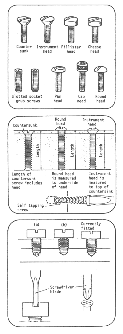
SECURING AND FIXING DEVICES
SCREWS
Screws are used for securing components and assemblies and are identified by:
1. Head type. Flush fitting screws are used when there is little clearance between assemblies or where protruding heads are not desirable.
The semi-flush type is used mainly for panel assembly or where a pleasing appearance is required.
The other full head types are used for general assembly work. As these heads are non-registering, some adjustment can be made to the relative positions of the workpieces by using the full clearance.
2. Screw length. Parts of the screw which protrude above the surface being fixed are not included when defining the length of the screw.
3. Thread type. Various types of thread are available such as:
Metric
BA (British Association)
UNF (Unified National Fine)
UNC (Unified National Coarse)
Self tapping.
Screws will normally be screwed into tapped holes or used with nuts.
If the hole is blind, ensure (a) that there is no swarf in the bottom of the hole, or (b) the screw is not too long. The screw should be 0.06 inches (1.5 mm) shorter than the depth of thread plus the thickness of the part being secured.
Ensure that the blade of the screwdriver is a good fit in slotted head screws or damage to the slot will result.
Ensure that the correct type of screwdriver is used when fitting hexagon socket/cruciform slotted screws.
FIG. 17 TYPES OF SCREWHEADS
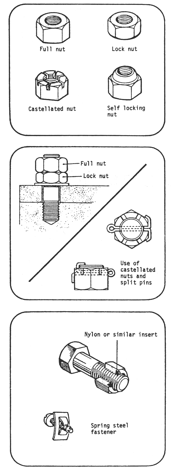
NUTS
Standard hexagon nuts are manufactured in two thicknesses:
Full nut - used singly with or without a locking washer.
Lock nut - used to lock another nut into a fixed position on a thread.
Special-purpose nuts include:
Castellated nuts for use with split pins.
Self locking nuts with nylon inserts.
Spring steel self locking fasteners.
USE OF LOCK NUTS
A lock nut is placed UNDER the main nut and tightened.
The main nut is run down on top of the lock nut and is tightened with one spanner while a second spanner prevents the lock nut from turning.
NOTE: The practice of placing the lock nut on top of the full nut weakens the assembly as the smaller number of threads in the lock nut take the strain.
USE OF CASTELLATED NUTS
Assemble bolt with castellated or slotted nut.
Drill clearance hole through bolt shank in line with slots.
Push split pin through hole until head meets nut.
Trim split pin ‘ends’ to length.
Bend ends tightly around nut.
NOTE: Do not use split pins more than once.
When used in conjunction with proprietary lock nuts, the screw should protrude by at least one thread.
FIG. 18 TYPES OF NUTS
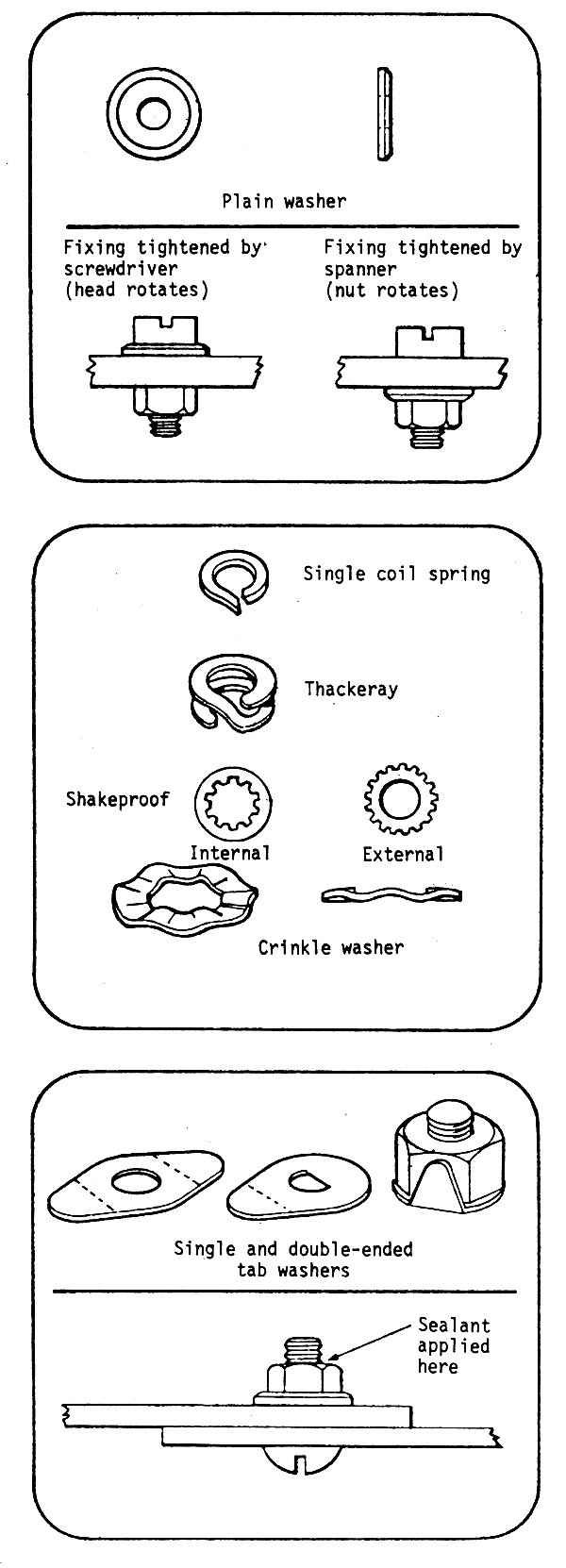
WASHERS
Plain washers are inserted under screw heads or nuts to provide a suitable bearing surface while tightening and to protect the component from damage due to rotation of the nut or screw head.
LOCK WASHERS
Locking washers are used to prevent loosening due to vibration, movement or temperature variation. Common types include:
SINGLE COIL spring washers normally made of square section spring steel, cut, twisted and chisel-edged.
THACKERAY DOUBLE COIL spring washers made of flat section steel or phosphor bronze.
SHAKEPROOF WASHERS punched from spring steel. The outer or inner edge is slit radially in a number of places and the segments in between the slits are twisted so that several sharp edges bear against nut and work.
CRINKLE WASHERS made from beryllium copper are used where a lighter spring pressure is required.
TAB WASHERS, used in special applications where a more positive locking action is required. The tab is bent up against the nut face, thus preventing it from turning.
LIQUID SEALANTS
These may be used to provide a permanent lock to a fixing point.
The sealant should be applied to the point where the thread emerges from the nut, using a small brush or the nozzle of the sealant container.
FIG. 19 TYPES OF WASHERS
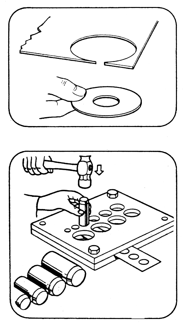
Ensure that shim is flat.
Holes can be punched in shim, using a close fitting plain punch and two plates bolted and dowelled together.
Select a punch of the correct size.
Place shim between plates and align position of marked hole with hole in plate.
Place punch in hole and strike with hammer.
Remove punch, release plates and remove shim.
FIG. 20 SHIMS USED AS PACKING
Bearings reduce friction between moving and stationary machine parts. They are designed for minimal wear, and by being replaceable, save wastage of expensive machine parts.
HANDLING BEARINGS
The working surfaces of bearings are either honed or very soft; if these surfaces are damaged, the bearing is ruined, therefore:
Handle bearings carefully to prevent damage.
Keep bearings wrapped until fitted, to keep out dirt.
Protect bearings against corrosion during storage, e.g. steel bearings must be oiled.
INSTALLING BEARINGS
Before any bearing is fitted:
Clean the journal or housing thoroughly and the seatings of the locating devices.
Inspect the surfaces for damage, do not fit bearings to damaged surfaces.
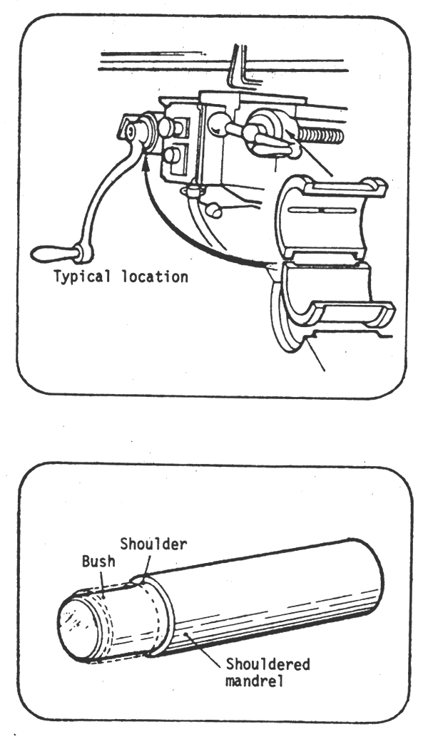
PLAIN BEARINGS
These are shells or bushes in which shafts run. They are made of different materials from the shaft.
FITTING A BUSH USING AN ARBOR PRESS
NOTE: A shouldered mandrel must be used when a bush is fitted, to prevent deformation. Use the correct size of mandrel.
FIG. 21A TYPES OF BEARINGS
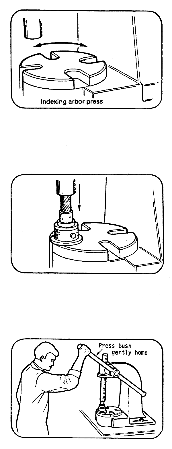
Clean the housing, the mandrel and the base of the arbor press thoroughly.
Coat the housing and the mandrel with light oil.
Index the base of the arbor press round to give the most suitable hole size.
Fit the bush on to the mandrel.
Align the bush with the housing and lower the ram on to the mandrel so that the ram holds the bush in position, above the housing.
Check that the BUSH is square to the HOLE.
Gently press the bush home with the lever.
After fitting, check the internal dimensions.
NOTE: Some bushes are secured by locking compounds and only a light push fit is required. Indexing arbor press
FIG. 21B TYPES OF BEARINGS
Split shell bearings fit directly on to the shaft. A split shell bearing is fitted after removing the old shells and after cleaning the journal and the shell seatings. When putting the new shells into their housing, care should be taken for proper alignment of the oil holes. Prior to assembling, all parts must be coated with appropriate lubricants. The shaft should be running freely and the bearing should remain cool under running conditions.
Ball and roller bearings have a stationary and a revolving race between which rolling balls or rollers prevent sliding friction. The stationary race is usually a light push fit whereas the revolving race is a press fit; therefore it is fitted to the machine first.
When fitting a bearing, force is applied only to the race in contact with the housing or shaft. The race must be square to the shaft. Preferably arbor presses should be used for fitting bearings. Figs. 22A/22B/22C show the procedures used, illustrating the pressing of a bearing on to the shaft. The square machined tube should touch only the inner race.
Fig. 22C shows the pressing of a shaft into a bearing supported by the inner race only. The force must be applied to the outer race only when the bearing is pressed into the housing. Bearings should only be tapped into place when they cannot be pressed into position as shown in Fig. 22B.
In some instances locating devices are used to position bearings on shafts or in housings. They have to be cleaned, coated with light oil prior to use, and must only mate with the face that has to be located, holding the bearing evenly around its circumference.
Removal of bearings requires careful handling so that seatings and bearings for re-use are removed without being damaged. During removal force must be exerted only on the race being extracted, and pullers should never be clamped to the working surfaces of the bearings. Whenever possible arbor presses should be used for bearing removal, as when fitting bearings into position. If arbor presses cannot be used properly, selected pullers can be substituted for them, as shown in Figs. 23A/23B. Bearing removal screws are used in some housing equipped with tapped and countersunk holes behind the bearing. The holes are fitted with short screws to keep the threads clean. When removing the bearing these screws should be removed from the holes, and the same number of longer screws fitted and tightened equally by small amounts to remove the bearing slowly from its housing (Fig. 23B).
Handling and maintenance of bearings, particularly ball and roller bearings, require the greatest possible care, as do all critical mechanical parts, mainly to avoid mechanical abuse and corrosion. As far as possible bearings should be protected against moisture. When moisture is present the selection of proper lubricants can help to run the bearings successfully under these more severe conditions. Discoloration and metal smearing is an indication of a bearing operating with inadequate lubrication. Temperature is usually considered a fair indication of the condition of the bearing, although grease lubricated bearings can operate at temperatures as high as 80° to 90°C. The temperature at which the bearing can work depends mainly on the type of lubricant used. In most cases in milk processing machines the temperature of the bearings does not exceed 50°C under normal operating conditions. This can be felt by placing the land lightly against the housing or the shell of the bearing. If it feels hot, the bearing should be inspected more closely. Wear of properly selected and properly lubricated bearings occurs only when foreign matter mixes with the lubricant and distorts the alignment of the races. Dirt causes most of the early bearing failures.
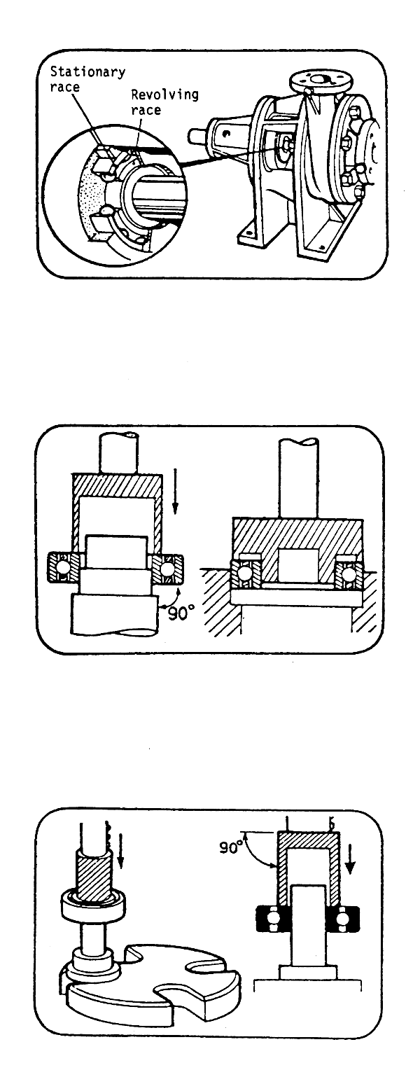
BALL AND ROLLER BEARINGS
These bearings have balls or rollers which prevent sliding friction by rolling between the races.
As bearings are used between stationary and revolving machine parts, such bearings have a stationary and a revolving race.
Normally, the revolving race is a press fit, so it is fitted to the machine part first, and the stationary race is a light push fit, so it is assembled with the machine part.
Bearings are precision-made of hard, brittle materials. Therefore, when force is applied to fit them:
Coat the journal or housing with clean, light oil.
Only apply force to the race in contact with the housing or shaft.
Keep the bearing square to the housing or shaft.
FITTING A BEARING, USING AN ARBOR PRESS
1. Whenever possible, use an arbor press, because it keeps the bearing square to the shaft or housing. Decide which is the best way to set the job up on the press:
Pressing a bearing onto a shaft. Use a tube to distribute the force evenly to keep the bearing square to the shaft. The tube must only touch the inner race and its ends must be machined square.
Pressing a shaft into a bearing. The bearing must be supported by the inner race only.
Pressing a bearing into a housing. A tube or flat block must be used so that the force is applied to the outer race only.
FIG. 22A FITTING BEARINGS
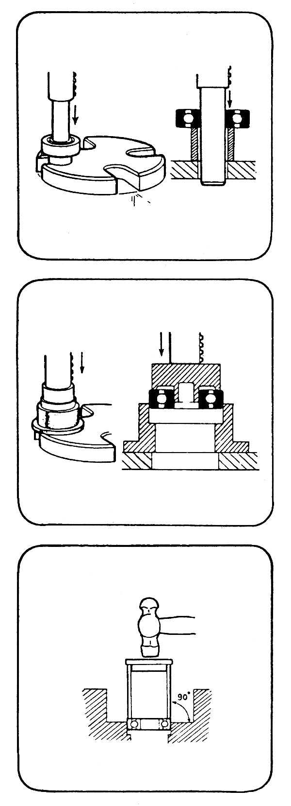
2. Operating the press.
Set up the part on the base of the press.
Align the part to be pressed into place and lower the ram to just hold it.
Check that the parts are square to each other.
Gently press the bearing home.
Check the bearing is positioned correctly.
TAPPING BEARINGS INTO PLACE
Bearings should only be tapped into place when they cannot be pressed into position. Decide which is the best method.
1. Using the tube and striking block. This is the best method, since the bearing can more easily be kept square to its seating.
FIG. 22B FITTING BEARINGS

2. Using a drift. Tap evenly around the race being fitted. Take care to keep bearing square to seating.
The method is useful when the seating is in an awkward situation. Take care to prevent foreign matter from entering the bearing.
Align the bearing with its seating and start to fit it by hand. A soft mallet may be used if necessary.
Tap the bearing home gently, stopping frequently to check that it is square.
THRUST RACES
Thrust bearings are ball or roller bearings specially designed to take end loads only.
FIG. 22C FITTING BEARINGS
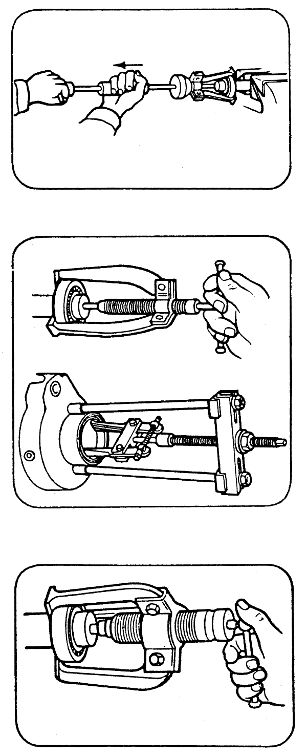
USING BEARING PULLERS
When using bearing pullers take care to keep the bearing square to the shaft.
Select the most suitable puller:
Impact pullers are only suitable for small bearings; the weight must be held when it is tapped against the stop.
Screw pullers are suitable for most purposes: take care to keep the puller square when turning the screw.
Hydraulic pullers are to be used when a large force is required.
Arrange the pullers inside or outside the bearing as required.
Fit the puller and tighten it to hold it in position.
Check that the puller is square and bearing only on the correct surfaces.
Pull the bearing slowly. Stop frequently to check that the bearing puller is square.
FIG. 23A BEARING PULLERS

PULLER PLATES
When a bearing mounted on a shaft is to be re-used, a puller plate should be used so that the force is exerted against the inner race.
BEARING REMOVAL SCREWS
Some housings have tapped and countersunk holes behind the bearing. These holes are normally fitted with short screws to prevent the threads becoming blocked with dirt.
To remove the bearing:
Remove the screws from the holes.
Select the same number of screws that will fit the holes and are long enough to remove the bearing.
Fit the longer screws and tighten them equally by small amounts to remove the bearing slowly from its housing. Take care to keep the bearing square to its housing.
FIG. 23B BEARING REMOVAL SCREWS
FAO TECHNICAL PAPERS
FAO ANIMAL PRODUCTION AND HEALTH PAPERS:
| 1. | Animal breeding: selected articles from World Animal Review, 1977 (C* E*F* S*) |
| 2. | Eradication of hog cholera and African swine fever, 1976 (E*F* S*) |
| 3. | Insecticides and application equipment for tsetse control, 1977 (E* F*) |
| 4. | New feed resources, 1977 (E/F/S*) |
| 5. | Bibliography of the criollo cattle of the Americas, 1977 (E/S*) |
| 6. | Mediterranean cattle and sheep in crossbreeding, 1977 (Bi. E/S*) |
| 7. | Environmental impact of tsetse chemical control, 1977 (E* F*) |
| 7 Rev. | Environmental impact of tsetse chemical control, 1980 (E* F*) |
| 8. | Declining breeds of Mediterranean sheep, 1978 (E* F*) |
| 9. | Slaughterhouse and slaughterslab design and construction, 1978 (E* F* S*) |
| 10. | Treating straw for animal feeding, 1978 (C* E* F* S*) |
| 11. | Packaging, storage and distribution of processed milk, 1978 (E*) |
| 12. | Ruminant nutrition: selected articles from World Animal Review, 1978 (C* E* F* S*) |
| 13. | Buffalo reproduction and artificial insemination, 1979 (E**) |
| 14. | The African trypanosomiases, 1979 (E* F*) |
| 15. | Establishment of dairy training centres, 1979 (E*) |
| 16. | Open yard housing for young cattle, 1981 (E* F* S*) |
| 17. | Prolific tropical sheep, 1980 (E*) |
| 18. | Feed from animal wastes: state pf knowledge, 1980 (E*) |
| 19. | East Coast fever and related tick-borne diseases, 1980 (E*) |
| 20/1. | Trypanotolerant livestock in West and Central Africa, 1980 Vol. 1 - General study (E* F*) |
| 20/2. | Trypanotolerant livestock in West and Central Africa, 1980 Vol. 2 - Country studies (E* F*) |
| 21. | Guidelines for dairy accounting, 1980 (E*) |
| 22. | Recursos genéticos animales en América Latina, 1981 (S*) |
| 23. | Disease control in semen and embryos, 1982 (E* F* S*) |
| 24. | Animal genetic resources - conservation and management, 1981 (E*) |
| 25. | Reproductive efficiency in cattle, 1982 (E*) |
| 26. | Camels and camel milk, 1982 (E*) |
| 27. | Deer farming, 1982 (E*) |
| 28. | Feed from animal wastes: feeding manual, 1982 (E*) |
| 29. | Echinococcosis/hydatidosis surveillance, prevention and control: FAO/UNEP/WHO guidelines, 1982 (E*) |
| 30. | Sheep and goat breeds of India, 1982 (E*) |
| 31. | Hormones in animal production, 1982 (E*) |
| 32. | Crop residues and agro-industrial by-products in animal feeding, 1982 (E/F*) |
| 33. | Haemorrhagic septicaemia, 1982 (E*) |
| 34. | Breeding plans for ruminant livestock in the tropics, 1982 (E* S*) |
| 35. | Off-tastes in raw and reconstituted milk, 1983 (E* F* S*) |
| 36. | Ticks and tick-borne diseases: selected articles from World Animal Review, 1983 (E* F* S*) |
| 37. | African animal trypanosomiasis: selected articles from World Animal Review, 1983 (E* F*) |
| 38. | Diagnosis and vaccination for the control of brucellosis in the Near East, 1983 (E*) |
| 39. | Solar energy in small-scale milk collection and processing, 1983 (E*) |
| 40. | Intensive sheep production in Near East, 1983 (E*) |
| 41. | Integrating crops and livestock in West Africa, 1983 (E*) |
| 42. | Animal energy in agriculture in Africa and Asia, 1984 (E/F*) |
| 43. | Utilisation des sous-produits de l'olivier en alimentation animale dans le bassin méditerranéen,(F*) |
| 44/1. | Animal genetic resources conservation by management, data banks and training, 1984 (E*) |
| 44/2. | Animal genetic resources: cryogenic storage of germplasm and molecular engineering, 1984 (E*) |
| 45. | Maintenance systems for the dairy plant, 1984 (E*) |
FAO PLANT PRODUCTION AND PROTECTION PAPERS: 57 titles published
FAO CONSERVATION GUIDES: 8 titles published
FAO FORESTRY PAPERS: 49 titles published
FAO FOOD AND NUTRITION PAPERS: 31 titles published
FAO AGRICULTURAL SERVICES BULLETINS: 60 titles published
FAO IRRIGATION AND DRAINAGE PAPERS: 41 titles published
FAO SOILS BULLETINS: 53 titles published
C - Chinese
E - English
F - French
S - Spanish
* Available
** Out of print
*** In preparation
Availability October 1984
The FAO Technical Papers are available through the authorized FAO Sales Agents or directly fròm Distribution and Sales Section, FAO, Viale delle Terme di Caracalla, 00100 Rome, Italy.
