A brackishwater fishpond is said to be properly designed when the arrangement of the pond compartments, water control structures and all other facilities mutually harmonize each other giving the most efficient water management and manipulation of stock.
A buffer zone of at least 100 meters from the sea to the main peripheral dike or 20 meters along river banks should be left undisturbed for ecological reasons and physical protection from flooding and wave action.
The main gate should be placed at one side of the pond where fresh unpolluted sea or brackishwater is available during spring tides. If possible another main gate should be alloted in areas accessible to low saline rivers for better control of salinity during summer months. The main gate should be located preferably at a straight stretch of the stream and should not be located at the corner of the dike, nor facing the open sea. Secondary and tertiary gates are located on the shorter side of the pond, preferably near the corner, to provide a much better circulation of water within the pond as tide water is let in. If drainage channels are provided, outlet gates draining to these channels will be placed at corners diagonally opposite the inlet gates.
In areas where the water supply is heavily laden with silt or mud, it may be necessary to provide a settling pond.
Whenever possible the longer dikes should be parallel to the direction of the prevailing winds so that there is less damage on dike due to wave action.
If necessary, diversion canals placed more or less perpendicular to direction of run-off or flood flow should be provided and they should be large enough to carry surface run-off during times of flood. This canal should be as short as possible and discharge to the nearest stream or channel.
a. Nursery Pond (NP). Nursery ponds or “Similyahan” should not be located adjacent to perimeter dikes. Crab holes and leaks that might open into the pond during the culture process will serve as direct exits of fries from the nursery pond to the river. These will also serve as direct entrance of predators and other unwanted species into the nursery pond, and if this happens it will cause loss of stock.
The nursery pond comprises about one percent of the total production area. The most suitable place is where it can be easily supplied with fresh unpolluted water all the time, and at elevation where it can be readily drained even during ordinary low tides. A manageable area ranges from 500 to 10,000 sq.m. per compartment although 1,000 to 5,000 sq.m. per compartment is preferred.
b. Transition Pond (TP). The transition pond or “bansutan” is located adjacent to the nursery pond in order to have an effective and easy transfer of fry. It comprises about 9 percent of the total production area. It is in this pond where fingerlings are stocked and stunted before they are transferred to the rearing pond. The pond bottom of the transition pond is constructed a little bit lower than that of the nursery pond. A manageable area ranges from 1,000 to 20,000 sq.m. per compartment although 5,000 to 15,000 sq.m. is preferred.
c. Rearing Pond (RP). The rearing pond is the largest compartment in the pond system. It comprises about 80 percent of the total production area. It is in this pond where the fingerlings are raised to marketable sizes. Whenever possible its pond bottom elevation will be constructed at least 15 cm. lower than the transition pond's bottom, hence, it must not be lower than the mean low water (MLW). A manageable size ranges from 1.0 to 7.0 hectares per compartment although 2.0 to 5.0 hectares per compartment is preferred specially in type II weather condition.
d. Feed Pond (FP) (Optional). In fishpond areas where natural food does not grow well and supplementary feeding is a necessity, one of the RPs, TPs or NPs could be utilized as a “feed pond”. The sole purpose of this pond is to produce food such as lab-lab, lumut or plankton, whichever is desired, for use either as supplemental feed or for fattening the fish before they are harvested. It should be a separate compartment ideally located near the pond where supplementary feeding is intended. The recent practice is to apportion at least one hectare of feed pond for every five hectares of rearing pond. Lab-lab or plankton transfer may be effected by water flow through the gates, while lumut are manually gathered and applied to the pond by spreading.
e. Catching Pond (CP). A catching pond, as the name implies, serves as a catchment basin for fish at harvest, It is constructed at the gate inside the pond where it is intended to be used. A catching pond intended for the nursery and transition ponds must be at least two percent of the compartment's watered area and one to one-and-one-half percent if it is intended for the rearing pond.
A catching pond is linked to the pond by way of a gate. Catching ponds, together with dikes and canals, generally cover about ten percent of the total production area.
a. Nursery Pond (NP). Considerations for the nursery pond in the modular system are the same as in the conventional system except that, in the modular system, the size of the nursery pond depends primarily on the fingerling requirements of the rearing ponds based on the maximum yearly targeted production. More or less, the nursery pond comprises about four percent of the total production area.
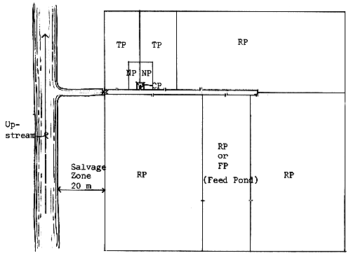
Figure 22. Example of a Conventional Pond System
b. Transition Pond (TP). Considerations for the transition pond are the same as in the conventional system, except that in the modular system, the transition pond covers only about six percent of the total production area.
c. Production Process Stages (PPS). In the modular system, the rearing pond is divided into three stages called production process stage one (PPS1), production process stage two (PPS2), and production process stage three (PPS3). The main idea is to transfer the fingerlings from the smaller module to the next larger module. The ratio of the area of the three PPS is 1:2:4. Some fish culturists prefer a ratio of 1:3:9 and others modify the method by transfering the stock only once.
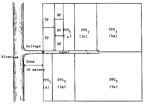
Figure 23. Example of a Modular Pond System
a. Nursery Pond (NP). Considerations for the nursery pond should be the same as in the conventional and the modular systems. There will be at least two nursery ponds comprising six percent of the total production area.
b. Fish Holding Canal (FHC). The purpose of a holding canal is to hold fingerlings when the rearing ponds are being prepared. It is connected to the rearing ponds, in such a way that each rearing pond will have a separate holding canal covering at least one percent of the RP's area.
c. Rearing Pond (RP). Considerations for the rearing pond should be the same as in the conventional pond system. The rearing pond covers 94% of the total production area including fish holding canals. The general practice is to stock at different times different size-groups of fingerlings and harvest the bigger ones selectively with the use of a gill net. This system yields well in Chanos chanos/Penaeus monodon polyculture.
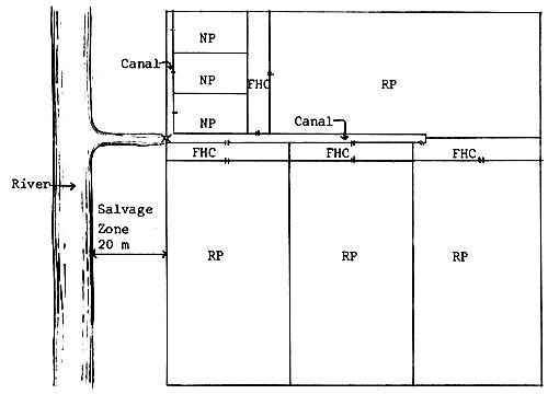
Figure 24. Sample Layout of a Pond by Multiple Stock/Harvest System
A gate is either a sluice, culvert, or pipe which is used to control water flow. Basically, it consists of the following parts:
Floor. The floor serves as the foundation of the structure and its elevation must be lower than the pond bottom elevation. The floor of the main gate must not be exposed even during extreme low tides.
Apron. The apron generally rests on the foundation piles, which are made of seasoned bamboo driven at 0.3 m. intervals into the soft soil with the butt end up. The apron serves as protection to scouring and future seepage of water at the gate's sides.
Cut-off-walls. Cut-off-walls are provided at both ends of the gate floor to prevent seepage and undercutting of water over the gate's foundation. They extend down into the soil at a minimum depth of 0.60 m. and are an integral part of the gate's foundation. Wooden sheet piles may be used for cut-off-wall.
Side or breast walls. Side walls define the sluice way in addition to their being retaining wall for the dike fill. Grooves or double cleats for flashboards and screens are built on these walls. The top of these walls are as high as the top of the dike.
Wing walls. Wing walls provide the transition from the sluice way into the main canal in addition to retaining the earth at both sides of the gate. This transition improves the hydraulics of the flow by providing a control on flow velocities from one bed material to another.
Bridge or Catwalk. This is a reinforced concrete slab or thick wooden planks that span the side walls. At least two catwalks are provided, located at regular intervals near the flashboard grooves.
Flashboards. Slabs or flashboards are generally wooden pieces, 1"-1 ½" × 10" inserted into grooves or double cleats. They are used to control the amount of water flowing through the gate.
Screens. Screens are usually made of bamboo strips or of fine polyethylene meshes attached to a wooden rectangular frame that fit into the grooves. The screens are used to prevent the exit of the cultured fish and the entry of predators into the pond.
Pillars. In wooden gates, these are vertical supports where wooden walls are nailed. They are placed at regular intervals so that they form a frame work.
Braces. In wooden gates, these wooden frames hold or fasten two or more pillars together or in place. They control the steady opening of a gate.
a. Main Gate. The main gate links the pond system to the source of water. It regulates the exchange of water between the pond system and the tidal stream or sea. It should be made of concrete for effective control and to last longer. The main gate is usually situated at the central side of the proposed fishpond facing the source of water. The following provides some information needed in the design of the main gate:
The floor elevation of the main gate should be lower than the lowest pond bottom elevation desired inside the pond system. It should also be lower than extreme low tides. Preferred elevation is -0.30 m. or 0.30 m. lower than the zero datum.
The height of the main gate depends upon the top elevation of the main dike which is also dependent upon the tidal fluctuation, flood and other factors in the area.
The opening of the main gate depends upon how large the area to be flooded. Experience tells us that a 1.0 meter opening main concrete gate will flood a 10–15 hectare pond system in two to three successive high tides. Fishpond areas of more than 15 hectares will require a multiple opening gate. Each opening will not exceed 1.2 m. wide for easy manipulation of slabs and screens.
There must be a separate groove for the slabs and screens. It may be necessary to have four pairs of grooves; two pairs for slabs and two pairs for screens depending upon their use.
The wings should be properly designed to provide easy current flow. The best angle of inclination should be 45° towards the outside.
The gate foundation must be tough and stable. It must be hard enough to carry the whole weight when the gate is constructed.
Cut-off-walls and aprons must be provided. They must be wide enough to include portions susceptible to scouring and undercutting of water.
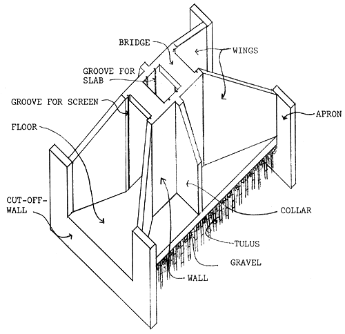
Figure 25. Sample Design of a Concrete Main Gate
b. Secondary and Tertiary Gates. Secondary and tertiary gates provide the control of water to and from the main canal and into the pond. These structures are usually made of wood and can be treated for durability by the application of coal tar. Reinforced concrete can also be used but is sometimes too expensive to be practical. Considerations in the planning and designing of secondary and tertiary gates are the same as those of the main gate except that their respective elevations are dependent upon the elevation of the canal where it is being constructed.
Secondary and tertiary gates are usually located centrally at the shorter compartment side along the canal. It is believed that better circulation of water during pond flooding is obtained if two gates are placed near the corner of the pond diagonally opposite each other in a case where drainage canals are provided. Relative location of these structures are shown on illustration showing basic pond layouts.
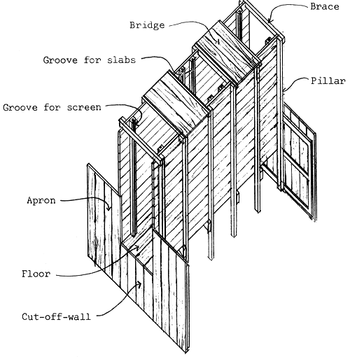
Figure 26. Sample Design of a Wooden Gate
c. Culvert or Pipe. A recent innovation for a smaller and less expensive gate is the use of culverts or pipes made of concrete hollow blocks or asbestos cement although they can be made of wooden boards. Culverts or pipes are likewise provided with slabs and screens and are even more effective water control in a fishpond. The details of construction of this type of gate is shown in Figure 27.
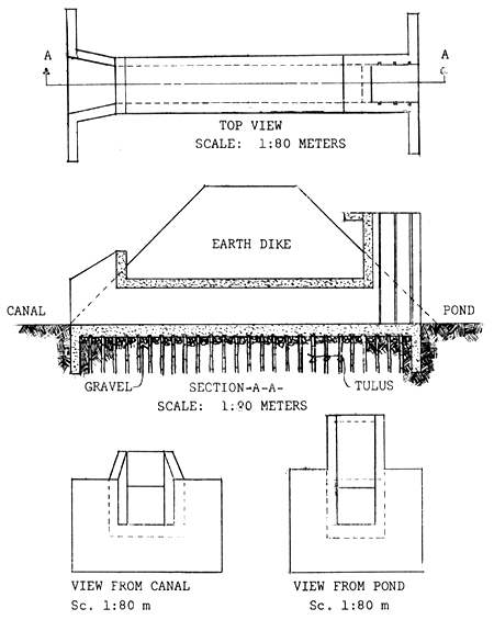
Figure 27. Sample Design of a Culvert Gate
Dikes compose the system of partitioning in the fishpond area for water control and stock separation. They are made of soil material found in the area where they are constructed. Dikes are trapezoidal in shape in cross-section with the top width, the side slopes and the height proportionally designed according to the soil material used. They must be of adequate size and shape to hold the water as well as prevent the seepage under or through the dike.
a. Height above the waterline. The top of the dike should extend sufficiently above the waterline to give a safe margin against overtopping at high tide and flood, and such allowance should include wave action caused by exposure to winds. The designed height of a perimeter dike normally has a free board, after shrinkage and settlement of 0.6 to 1.0 m. above the maximum flood water level observed in the locality for at least 10–15 years. Freeboard for secondary and tertiary dikes is usually 0.30 m.
The allowance for settlement and shrinkage depends on the characteristic of the soil fill, soil foundation and on the method of construction. It is expressed as a percentage of the dike height. Because of poor materials and poor methods and practices in construction, an allowance of 25% for settlement and shrinkage is used. For soils exceptionally high in organic matter, the settlement allowance should not be less than 40%. When the dike is compacted by construction equipment, a settlement of an additional 5% of the fill height should be included.
b. Top Width. There are several recommendations for determining the top width of an earth dike. The minimum recommended width for dikes less than 3.0 m high is 2.4 m. For dikes used as roadway, a width of at least 4.0 m. is specified. This width provides space for roadway and shoulder on each side. The width of dikes used as roadway for access to ponds should be at least 3.5 m., but preferably 4.0 m. “Bangus” pond dikes in the Philippines use a minimum top width of 2.0 m. for main dikes, 1.5 m. for secondary dikes and 1.0 m. for tertiary dikes. For dikes subjected to wave action, the minimum top width is approximately equal to the height of the maximum wave. A 0.6 m. wide shoulder should be provided on each side of a roadway dike to prevent ravelling.
c. Side Slope. The side slope (ratio of horizontal to vertical) is a function of the type of soil used. The side of the dike inside the pond which is saturated all the time is generally flatter than the outer side which is dry. If both sides are saturated, both side slopes are the same.
Fishpond dikes constructed lower than 4.26 m. should have a slope of 1:1. Dikes constructed above 4.26 m. should adopt 2:1 slope.
d. Design height
The design height of a main dike is calculated using the following formula:

Where:
| Hm | = | Height of the main dike |
| HAT | = | Highest Astronomical Tide |
| GS | = | Elevation of the ground Surface |
| MF | = | Maximum Flood level |
| FB | = | Allowance for Free Board |
| %S | = | Percent Shrinkage and settlement |
The design height of a secondary dike is calculated using the following formula:

Where:
| Hs | = | Height of the secondary dike |
| HST | = | Highest Spring Tide |
| GS | = | Elevation of the ground Surface |
| MR | = | Maximum Rainfall within 24 hours |
| FB | = | Allowance for Freeboard |
| %S | = | Percent Shrinkage and settlement |
The design height of a tertiary dike is calculated using the following formula:

Where:
| Ht | = | Height of the tertiary dike |
| DWL | = | Desired Water Level |
| GS | = | Elevation of the ground Surface |
| MR | = | Maximum Rainfall within 24 hours |
| FB | = | Allowance for Freeboard |
| %S | = | Percent Shrinkage and settlement |
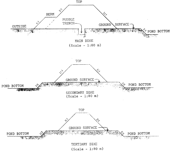
Figure 28. Design of Different Dikes
About one to two percent of the total farm area is used in the canal system. The main water supply canal starts from the main gate and usually traverses the central portion of the fishfarm. The canal bed should not be lower than, but rather sloping towards, the floor elevation of the main gate. Generally, the canal bed is given a slope of 1/1500 or one meter difference in elevation for a horizontal distance of 1,500 m. A one meter opening main gate will have a canal bed at least 3.0 m. wide. This width is enough to supply a 10–15 hectares fishpond system considering that the canal dikes have a ratio of 1:1 slope.
Secondary water supply canals are constructed in portions of the farm which cannot be reached by the main canal. It starts from the main canal and traverses the inner portion of the fishpond. It is usually constructed in large fishpond areas and smaller than the main canal. Generally, secondary supply canal has a bed width of 2.0 m.
A tertiary canal is usually constructed to supply water in the nursery and transition ponds. Because of the small size, it is sometimes said to be a part of the nursery pond system. Some fish culturists modify the tertiary canal as a catching pond. This usually happens when the designed tertiary canal is short, Generally, a tertiary canal has a bed width of 1.0–1.5 m.
A diversion canal, when necessary, is also constructed to protect the farm from being flooded with run-off water coming from the watershed. It must be strategically located so that run-off will empty on an established disposal area, natural outlets or prepared individual outlets. It should have the capacity to carry at least the peak run-off from the contributing watershed for a 10-year frequency storm. The slope of the diversion canal should be in such a way that water flows towards the drainage area.
A drainage canal is constructed when there is a need to have a separate canal for draining rearing ponds. This is to improve water management in the pond system. It is usually located at the other side of the pond, parallel to the supply canal. A drainage canal is recommended in intensive culture, especially of shrimps.
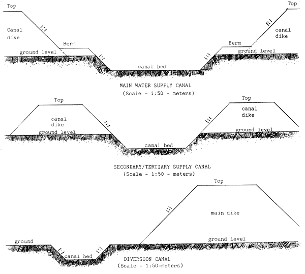
Figure 29. Design of Different Canals