A. General Description. The surveyor's compass (Fig. 11) is an instrument for determining the horizontal direction of a line with reference to the direction of a magnetic needle. The needle is balanced at its center on a “pivot” so that it swings freely in a horizontal plane. The pivot is at the center of a horizontal circle which is graduated to degrees and half-degrees, and numbered from two opposite zero-points each way to 90°. The zero-points are marked with the letters N and S, and the 90° points are marked E and W. The circle is covered with a glass plate to protect the needle and the graduations, the part enclosed being known as the “compass-bos”. A screw is provided for raising the needle from the pivot by means of a lever. The needle always should be raised when the compass is lifted or carried, to prevent dulling the pivot-points; a dull pivot-point is a source of error. Both the circle and the pivot are secured to a brass frame, on which are two vertical sights so placed that the plane through them also passes through the two zero-points at the circle. This frame rests on a tripod and is fastened to it by means of a ball-and-socket joint. On the frame are two spirit levels at right angles to each other, which afford a means of leveling the instrument. This ball-and-socket joint is connected with the frame by means of a spindle which allows the compass-head to be revolved in a horizontal plane, and to be clamped in any position.
The magnetic needle possesses the property of pointing in a fixed direction, namely, the “Magnetic Meridian”. The horizontal angle between the direction of this meridian and of any other line may be determined by means of the graduated circle, and this angle is called the “Magnetic Bearing” of the line, or simply its “Bearing”. If the bearings of two lines are known, the angle between them may be computed. Bearings are counted from 0° to 90°, the 0° being either at the N or the S point and the 90° either at the E or the W point. The quadrant in which a bearing falls is designated by the letters N.E., S.E., S.W., or N.W. For example, a line makes an angle of 20° with the meridian and is in the southeast quadrant, its bearing is written S 20°E. Sometimes the bearing is reckoned in a similar manner from the “true bearing”. In general, this will not be the same as the magnetic bearing. True bearings are often called “azimuths”, and are commonly measured from the south point right-handed (clockwise) to 360°; a line running due west has an azimuth of 180°; a line due east an azimuth of 270°. Sometimes, however, the azimuth is measured from the north as, for instance, when observing the azimuth of the Pole-Star.
B. Method of Taking a Magnetic Bearing. The surveyor's compass is set up (and leveled) at same point on the line whose bearing is desired. The needle is let down onto the pivot, and the compass sights pointed approximately along the line. While looking through the two sights the surveyor turns the compass-box so that they point exactly at a lining pole or other object marking a point on the line. The glass should be tapped lightly over the end of the needle to be sure that the latter is free to move. If it appears to cling to the glass this may be due to the glass being electrified, which condition can be removed at once by placing the moistened finger on the glass. The position of the end of the needle is then read on the circle and recorded. Bearings are usually read to the nearest quarter of a degree although it is possible to estimate somewhat closer.
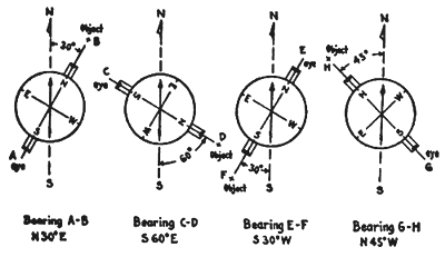
Since the needle stands still and the box turns under it, the letters E and W on the box must be reversed from their natural position so that the direct reading of the needle will give not only the angle but also the proper quadrant. When the north point of the compass-box is toward the point whose bearing is desired, read the north end of the needle. When the south point of the box is toward the point, read the south end of the needle. If a bearing of the line is taken looking in the opposite direction, it is called the “reverse bearing”. Reverse bearings should be taken to check for error. The following illustration demonstrates the proper method of taking a magnetic bearing.

Illustration: Method of Reading Bearings
In reading the compass-needle, the surveyor should take care to read the farther end of the needle, always looking along the needle, not across it. By looking at the needle sidewise it is possible to make it appear to coincide with a graduation which is really at one side. This error is called “parallax”.
C. The Earth's Magnetism. The earth is a great magnet. On account of its magnetic influence, a permanent magnet, such as a compass-needle, when freely suspended will take a definite direction depending upon the direction of the lines of magnetic force at any given place and time. If the needle is perfectly balanced before it is magnetized it will, after being magnetized, dip toward the pole. In the northern hemisphere, the end of the needle toward the north pole points downward, the inclination to the horizon being slight in low (magnetic) latitudes and great near the magnetic pole. In order to counteract this dipping a small weight, usually a fine brass or silver wire, is placed on the higher end of the needle at such a point that the needle assumes a horizontal position.
D. Declination of the Needle. The direction which the needle assumes after the counter weight is in position is called the magnetic meridian and this rarely coincides with the true meridian. The angle which the needle makes with the true meridian is called “declination of the needle”. When the north end of the needle points east of the true, or geographical north the declination is called “east”; when the north end of the needle points west of true north, it has a “west” declination.
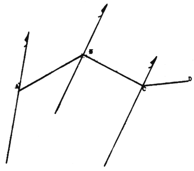
E. Detecting Local Attraction of the Needle. As the needle is always affected by masses of iron near the compass it is important that the bearings in any survey should be checked. This is most readily done by taking the bearing of any line from both ends or from intermediate points on the line. If the two bearings agree it is probable that there is no local magnetic disturbance. In the following illustration, suppose that the compass is at A and that the bearing of AB is N 50°E, and with the compass at B, the bearing BA is found to be S 48°30'W. It is exident that there is local attraction at one or both points. In order to ascertain the correct magnetic bearing, turn the compass toward a point C which is apparently free from magnetic disturbance, and observe the bearing of BC, which is say, S 72°E. Now move the compass to C and observe the bearing CB. If this is N 72°W it indicates that there is no local attraction of C or 8, hence, S 49°W is the correct bearing of line BA, and there is 2o error in all bearings taken at A. If the bearings of BC and CB had not agreed it would have been necessary to take the bearing and reverse bearing of a new line CD. This process is continued until a line is found whose bearing and reverse bearing differ by exactly 180°. In order to be certain, however, that these latter bearings are really free from attraction, several other stations should be checked. Since local attraction drags the needle to a fixed amount from the magnetic meridian it follows that the angles at any one point computed from the bearings are not affected by local attraction.

Illustration: Checking Compass Reading for Magnetic Disturbance