by
Kisto Mintardjo
Brackishwater Aquaculture Development Centre
Jepara, Indonesia
1. INTRODUCTION
In Indonesia, as in any other Asian countries, shrimp culture cultivation in ponds is a money-earning business. However, success in cultivation depends on suitability of sites; knowledge of correct management practices; proper pond layout and design; and adequate amount of capital investment. The primary important consideration which would determine the success or failure of the project is the proper selection of site for shrimp culture project.
The following discussion will deal mainly on proper identification of suitable sites for penaeid shrimp pond.
2. FACTORS TO CONSIDER IN SITE SELECTION
Identifying suitable sites for shrimp farming is rather complex process. There are several factors to consider in site selection. These can be divided into two, namely; a) the technical; and b) the non-technical factors.
The technical factors are: nature of water; tide fluctuation and ground elevation; type of soil; land topography; type of vegetation; flood hazard and wind direction.
The non-technical factors include: availability of skilled labour; source of seedling; accessibility to transportation; competing uses for land and nearby water; availability of technical assistance; availability and cost of supplies and equipment; marketing and market facilities.
2.1 Technical factors
2.1.1 Nature of water
Water is the first and most important consideration in the suitability of a shrimp farm. It should be available throughout the cultivation period. Water supply may come from tidal brackishwater, in rivers or from the sea.
The water should be free from agricultural and industrial pollution as well as from turbidity due to high organic load of mud and silt. A good water quality for shrimp pond should have a salinity of 10–25 ppt; pH range from 7 to 8.5 and a minimum level of dissolved oxygen of 5 ppm.
2.1.2 Tide fluctuation and ground elevation
The suitability of tide-fed area for fishponds depends on the relationship between the tidal characteristics and ground elevation of the area. This will show whether the pond could be filled up by tidal flow or by the use of pumps. In areas where the tidal fluctuation is between 2 to 3 m, the ponds can be filled up using tidal inflow. Areas where tidal fluctuation are large, over 4 m, are not suited for tidal ponds because very large and expensive dike would be constructed to prevent flooding during high tide. Areas with slight fluctuation, 1 m or less are also unsuitable for tidal ponds, because the ponds could not be filled or drained properly. If ponds are to be constructed in areas where the tide is less than 2 m or more than 3 m, the use of pumps should be considered (Jamandre and Rabanal, 1975). Figure 1 shows the relationship of tidal characteristics and elevation.
2.1.3 Type of soil
Most coastal areas where fishponds are constructed have soils that are high in peat or sand and very low water holding capacity. The potential pond soil should have high enough clay content to assure that the pond will hold water. A good field test to use in determining this is to shape a handful of moist soil into a ball; if the ball remains intact and does not crumble after considerable handling, there is enough clay in the soil to provide a water tight seal (Perry, 1972). Sandy clay or clay loam is best for dike construction because it is hard and does not crack when dry. Peaty soil is not a good dike material as it settles too much and may even burn when dried (Denila, 1976). Table 1 shows the relationship of soil classes and suitability for dike materials.
2.1.4 Land topography
Land topography may be denied as the configuration of the land surface. Such condition may be hilly, rolling, sloping or flat. These affect the development cost of the area selected.
Table 1. Relationship of soil classes and suitability for dike material*
| Class | Relative characteristic | Compaction characteristic | Suitability for dike material | |
|---|---|---|---|---|
| Permeability | Compressibility | |||
| Clay | Impervious | Medium | Fair to good | Excellent |
| Sandy clay | Impervious | Low | Fair to good | Good |
| Loamy | Semi-previous | High | Fair | Good |
to | to | |||
| Impervious | High | Very poor | ||
| Silty | Semi-pervious | Medium | Good | Poor |
to | to | to | ||
| Impervious | High | Very poor | ||
| Sandy | Pervious | Negligible | Good | Poor |
| Peaty | - | - | - | Very poor |
* Fishfarming Engineering, BFAR/UNDP-FAO Training Manual, p.8.
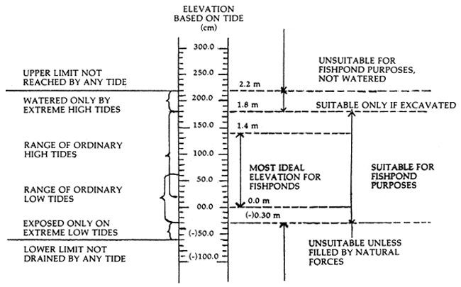
Figure 1. Suitability of proposed fishpond site based on tidal characteristic and ground elevation (From Jamandre and Rabanal, SCS/75/WP/16)
Low and flat areas will require high and more formidable dikes, which means that earth will have to be moved in form outside the site. If the area is also low, drainage will be a problem. However, hilly or mountainous areas should be ruled out as it is costly to move large quantities of soil during the process of excavation. There is also the problem of where to place the excess material. While this can be solved by constructing high and wide perimeter dikes, putting up more dikes will create narrow compartments resulting in less area for production. Moderately sloping areas and within the ideal tidal range should be selected. For economy the topography should be considered in design and layout of ponds.
2.1.5 Type of vegetation
Vegetation is a natural indicator whether the area is suited or not for aquaculture project. It has been observed that mangrove species like Rhizophora are mostly found in low areas while that of Avicenia abound in elevated areas. Presence of certain shrubs and ferns indicate the elevation and frequency of tide water inundating the area. Certain plants such as water lily, eel grass and chara sp. indicate low water salinity.
The type and density of vegetation, the size, wood density and root system of individual trees greatly affect the method of clearing, procedure of farm development and construction cost. Thickly vegetated areas, for instance, will take a long time to clear the stumps.
Density of vegetation is classified according to kind, size and quantity per unit area. This is done to determine the cost of land clearing and uprooting of stumps. One method used is by random sampling. The process requires at least five or more samples taken at random regardless of size. Vegetation is classified according to kind, size and number. The findings are tabulated and the average of the samples is determined. However, vegetation of less than 3 cm in diameter is not included. The total vegetation of the area is determined as follows:

Table 2 shows the classification of vegetation according to kind, size and quantity.
2.1.6 Flood hazard and wind direction
Flood occurrence, triggered by typhoons and monsoon rains prevailing over the area has to be considered in site selection. Flooding is largely attributable to bad channel characteristics such as steep slopes as well as meandering of water courses at the lower reaches of rivers. Since floods cannot be controlled, it is important to know how fishponds can be free to some extent from flood hazard.
Table 2. Classification of vegetation according to kind, size and quantity
| Nipa1 | Bakawan2 | Api-Api3 | Lipata4 | Biribid | ||||||
|---|---|---|---|---|---|---|---|---|---|---|
| Sample | No. | Ave. dia. | No. | Ave. dia. | No. | Ave. dia. | No. | Ave. dia. | No. | Ave. dia. |
| 20 m × 20 m | (cm) | (cm) | (cm) | (cm) | (cm) | |||||
| I | 232 | 24 | 0 | 0 | 0 | 0 | 2 | 21.5 | 0 | 0 |
| II | 162 | 18 | 26 | 8.6 | 10 | 33 | 1 | 33.5 | 1 | 27.3 |
| III | 392 | 38 | 0 | 0 | 6 | 34 | 3 | 17.9 | 0 | 0 |
| IV | 462 | 48 | 0 | 0 | 1 | 27 | 0 | 0 | 2 | 38.2 |
| V | 42 | 20 | 6 | 6.6 | 8 | 36.8 | 4 | 35.0 | 2 | 24.5 |
| Total | 1 290 | 146 | 32 | 15.2 | 25 | 130.8 | 10 | 107.9 | 5 | 90.0 |
| Average | 258 | 29.20 | 6.4 | 3.04 | 5 | 26.16 | 2 | 21.58 | 1 | 18.0 |
| Percentage | 94.7 | 7.9 | 2.4 | 0.8 | 1.8 | 7.0 | .7 | 5.8 | .4 | 4.9 |
1 (Nypa fruticans)
2 (Rhizophora spp.)
3 (Avicennia alba)
4 (Excoecaria agallocha or Cerbera manghas)
In order to prevent flooding, it is necessary to know the weather conditions in the locality. The highest flood occuring in the area can be determined by proper gathering of information. The best way is from the people who have stayed in the area for many years. The size of creeks, rivers and drainage canals should also be determined to find out whether it can accommodate the run-off water or flood waters that drain in the area once the fishpond is developed.
Wind on the other hand, plays a role in fishpond design. Strong wind generates wave actions that destroy the sides of the dikes. This causes great expense in construction and maintenance. However, this problem can be minimized with proper planning and design. For instance, longer pond dimension should be positioned somewhat parallel to the direction of the prevailing wind (Figure 2). This will lessen side length of the dike exposed to wave action. This orientation of pond compartments will also have some advantageous effect in the management of the fishpond.
2.2 Non-technical factors
2.2.1 Availability of skilled labour
As much as possible local labour available in the locality or adjacent to the project site is usually the cheapest. There will be savings in housing, transportation, food and other expenses because if workers are brought in from other areas, they will have to be paid for these expenses. It is also important to know the customs and traditions of the local people, as this will greatly affect the funding for labour. Identify the months when agriculture activities are greatest. This will help in formulating programmes for development, stocking and harvesting.
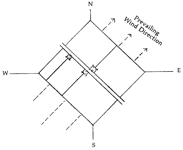
Figure 2. Layout of pond compartments oriented to the prevailing wind direction
2.2.2 Source of seedlings
Determine the availability of seeds from hatcheries or dealers who obtain their stocks from the wild. If seeds are not to be purchased, local resources must be assessed to determine the species present and their seasonality of abundance.
2.2.3 Accessibility to transportation
The area should be accessible to transport of both construction equipment and materials, and for daily operations. Cost can increase significantly if materials have to be carried far by hand. If access to the farm site is by water, make sure that travel is possible during monsoon period.
2.2.4 Competing uses for land and nearby waters
The use of nearby land and water have to be assessed to find out what effects, if any, they will have in the project. Activities to include such things as navigation, fishing, manufacturing industry, public utilities, recreation, nursery areas and other related problems can arise particularly if the activities of local people are disrupted. See to it that the project does not block traditional rights of way or interfere with other work or recreational activities.
2.2.5 Availability of technical assistance
Technical assistance can be from government extension services, research institutions and from financing institutions.
2.2.6 Availability and cost of supplies and equipment
It is important to know whether or not the supplies and equipment needed are available in the area or in the country. Fine mesh net material for screening is generally not available. Frequently, the variety of inorganic fertilizer is greatly restricted and cost may be higher for aquaculture use than for agricultural use. Manures or other organic fertilizers might be difficult to obtain or available only infrequently, requiring storage. In case materials will have to be imported, one should determine if there are restrictions or extra costs involved.
2.2.7 Marketing and market facilities
This is related to management. In case local buyers pay acceptable price, the best form of management may be to practice partial harvesting or to harvest one pond at a time, so that the local small market is not flooded. In case shrimp is shipped out to a distant market, it is better to plan the harvest and market large quantities at one time. Sometimes, buyers come to the farm to purchase the crop. If not, is ice available? Determine if the buyer will accept only whole shrimp or if just tails would be acceptable. If buyers will take tails, the heads can be removed at the pond and used as supplemental feed.
3. SITE EVALUATION
Taking into consideration the time, effort and amount of investment needed in going into any aquaculture project, a proper evaluation and a thorough study of the area is necessary to come up with a suitable site. The above considerations will help potential operators in determining areas suited for aquaculture projects.
It is quite difficult to find ideal sites for aquaculture. However, the above criteria should be borne in mind in the process of selecting sites for development. The least ideal sites would mean more capital investments to make them work which in effect would mean lesser returns or longer recovery period on investments.
REFERENCES
Anonymous, 1978 Manual of pond culture of penaeid shrimp. ASEAN National Coordinating Agency of the Philippines, Ministry of Foreign Affairs, Manila, Philippines.
Adisukresno, S., 1983 Criteria for site selection of coastal fishpond. Study/Seminar on Coastal Fishpond Engineering. South Surabaya, Indonesia. 4–12 August 1982.
dela Cruz, C.R. 1983 Fishpond engineering: A technical manual for small and medium scale coastal fishfarms in Southeast Asia. South China Sea Fish. Dev. Coord. Prog. SCS Manual No. 5.
Jamandre, T. and H.R. Rabanal, 1975 Engineering aspects of brackishwater aquaculture in the South China Sea region. South China Sea Fish. Dev. Coord. Prog. SCS/75/WP/16.
Lopez, J.U., 1980 Selection of suitable fishpond site for the culture of the giant freshwater prawn, Macrobrachium rosenbergii. South China Sea Fish. Dev. Coord. Prog. SCS/GEN/81/28:41–45.
Rabanal, H.R., 1976 Mangroves and their utilization for aquaculture. Phil. Jour. Fish. (14) 2:191–203.
Rosita. A.T. and M.B. Surtida, 1986 Site selection for brackishwater ponds. Aquaculture Technology Module No. 4. Aquaculture Department, Southeast Asian Fisheries Development Center, Tigbauan, Iloilo, Philippines.
Suharto, H., 1980 Site selection for freshwater prawn hatchery. South China Sea Fish. Dev. Coord. Prog. SCS/GEN/81 26:25–28.
ACKNOWLEDGEMENT
The author is grateful to Mr. Rodolfo C. Pinto, Supervising Fishery Technologist, Bureau of Fisheries and Aquatic Resources, Philippines, for technical editing of this material and to Mrs. Medina N. Delmendo, Project Coordinator, ASEAN/UNDP/FAO Regional Small-Scale Coastal Fisheries Development Project, for her comments and suggestions in the preparation of this lecture material for the Training Course on Shrimp Culture.
by
Bambang S. Ranoemihardjo
1. INTRODUCTION
Brackishwater pond or tambak in Indonesia covers a total area of 238 268 hectares in 1985 (Direktor Jenderal Perikanan, 1987). Milkfish and shrimps are the two species cultivated in tambak. The system of culture practices are either traditional, semi-intensive and intensive method. Although there have been improvements in pond culture techniques, it should be admitted, however, that many aspects, both from the viewpoints of pond engineering and pond management, still require further refinements and development.
The government aware of the need for developing the potential of tambak fisheries made steps to remedy the situation. New systems of brackishwater aquaculture practices have been introduced to farmers which include: new pond layout and design; use of pesticide for pest elimination; increased stocking density; introduction of artificial feed and use of aeration devices; and flow through water management systems.
Prior to the adoption of improved and new culture practices, production of shrimps is less than 100 kg per hectare per year; now some private tambak operators have produced about 10 tons per hectare per crop (4 to 5 months rearing) under intensive culture methods.
2. DEVELOPMENT PLAN AND DESIGN OF PONDS
The worst error a prospective fishpond operator can make is to develop an area without any program of activities. Money will be wasted and operation of the project may be difficult if not carefully planned. Poor planning is a major cause of project failure or even lead to bankruptcy due to infrastructure defects. Once constructed, the physical structures become permanent and would be difficult to correct.
The design and construction of fishponds are dependent on the characteristics of the site selected. This subject has been discussed in another lecture and will therefore not be repeated in this paper.
The farm is said to be properly designed when the arrangement of the pond system, water control structures, and all other facilities, complement one another to give the most efficient water supply and control features which makes the production system work efficiently.
2.1 Pre-development program
2.1.1 Preparation of feasibility study
Whether the operator will apply for a loan from banks or will use his own money to finance the development of the project, a feasibility study of the area is needed. The feasibility study will be the guide in the development and management of the project. All activities such as construction costs, operational costs and financial analysis to determine returns on investments are embodied in the feasibility study.
2.1.2 Survey of the area
A survey is necessary in the planning and development of the project. This includes a topography and relocation survey. It is necessary in the preparation of the layout and design.
2.1.3 Construction of temporary shelter and flat boats
The shelter will house the laborers in the project area while the flat boat to transport mud block.
2.2 Construction
2.2.1 Clearing of the area
Clearing the area of vegetation can be divided into three categories: a) cutting and chopping; b) falling and burning; and c) uprooting and removal of stumps and logs. Cost for the clearing depends upon the prevailing price in the locality and density of vegetative cover.
Initial clearing begins where the main dike and gates are to be located. Full scale clearing then continues as the construction of main dike and main gate proceeds. The entire area of the fishpond site should be cleared of all grasses, trees, roots and stumps. These are then burned or removed from the site.
2.2.2 Cost estimate of concrete gates
Cost of construction can be calculated based on the design and specification proposed in the area. Figure 1 shows the design of concrete gate.
(a) Based on the plan, determine the area and volume of the walls, wings, floors and toes, aprons and cut walls and compute for the total volume using the following formula:
| A | = | L × W |
| V | = | A × L |
| Vt | = | V = V1 + V2 + V3 |
Where:
| A | = | Area |
| V | = | Volume |
| Vt | = | Total volume |
| L | = | Length |
| W | = | Width |
| t | = | Thickness |
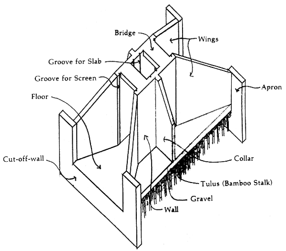
Figure 1. Sample design of a concrete main gate with single opening (BFAR)
(b) Determine the number of bags of cement and the volume of gravel and sand by multiplying the total volume with the factors pre-computed for Class A mixture plus 10 percent allowance for wastage, thus:
| No. of bags of cement | = | (Vt × 7.85) + 10% |
| Volume of sand | = | (Vt × .44) + 10% |
| Volume of gravel | = | (Vt × .88) + 10% |
Class A mixture has a proportion of 1:2:4. That is, one part cement for every two parts of fine aggregate sand and four parts of coarse aggregate gravel.
(c) For every square meter of a concrete gate use eight pieces of one meter long reinforcement bar placed at an interval of 0.25 m both ways on center. This is equivalent to 1.5 bars (1 standard reinforcement bar is equal to 6 meters or 20 feet long).
No. of reinforcement bar = (Af + At) × 1.5
Where:
Af = Area of the floor
At = Area of the toes
The walls, wings, etc. use different reinforcement bar space, 0.50 m both ways from center.

Where:
Aw = Area of walls
Ax = Area of wings
An = Other area
(d) Weight of the tie wire No. 16 is equal to total area times a standard value per sq m of concrete, thus:
Weight (kg) = At × 0.3 kg/sq m
(e) Calculate the volume of boulders by multiplying the area of the flooring with the thickness of fill.
(f) Form lumber can be calculated by multiplying the area of walls, wings and bridge by 2. Plywood can also be used as form. Use 2'' × 3'' plywood can also be used as form materials. Use 2'' × 3'' wood for form support.
(g) Bamboo post to strengthen the foundation could be calculated from the area of the flooring. A sq m of flooring will require more or less 20 pieces of whole bamboo posts at an interval of 0.25 m both ways on center.
(h) Screens and slabs are calculated based on the design of the concrete gate.
(i) Labor costs is 35–50 percent of the material cost.
2.2.3 Construction of concrete gate
Usually, the main concrete gate is constructed simultaneously or ahead of the perimeter dike. This is located at the lowest portion of the area adjacent to the main tidal water source. Prior to construction, all needed materials are transported near the site for easy access during the construction. This is constructed during the neap tide and should be completed before the coming of the spring tide.
The steps in construction are as follows:
Measure the area for the concrete gate and give space allowance of about 1–2 meters around for movement of the workers as markers are placed.
Enclose the area with temporary dike. This should be high and strong enough to withstand the pressure of the incoming tide; pump or bail out the water inside the enclosure.
Excavate the enclosed area to minus 0.6 m elevation. Remove stumps, roots and soft soil, if there is any.
Drive 2–3 m long bamboo posts over the entire area at one-meter interval. Leave 5 cm of the piles exposed.
Insert boulders about 20 cm thick between the piles to form the foundation. Spread gravel to level and cover the boulders; then compact.
Construct the form lumber for the flooring including the toes. Place reinforcement bars as per plan and tie wire No. 16.
Install vertical and horizontal reinforcement bars for side walls, wings and collar. Place reinforcement bars for the bridge and prepare the forms for walls, wings, etc.
Properly reinforce all forms to withstand pressure of the concrete mixture and pump water out, if necessary.
Prepare a Class A concrete mixture (1:2:4) and pour it in the form continuously until completed. While pouring, somebody should compact the mixture with the use of a long stick to prevent holes or hollows forming in the structure.
Allow concrete to harden for 2–4 days and then remove the forms.
Sprinkle fresh water on the curing concrete every day for two weeks and then remove the temporary dike after 30 days. Condition the gate by letting tidal water in and out of the pond.
Technical advice of aquaculture engineers regarding civil works in fishpond construction would be useful.
2.2.4 Construction and installation of wooden gate
Control of water to and from the internal pond system is usually made of wood. These are the secondary or tertiary gate. Reinforced concrete can also be used but this is quite expensive to beginners without adequate financial resources. For better water circulation during pond flooding, two gates are installed in a pond. These are located near the corner of the two shorter sides and diagonally opposite each other. Figure 2 is a sample of a wooden gate.
(a) Estimated cost of construction is based on the number of board feet (bd ft) used, using the following formula:

Where:
L = Length of lumber in feet
W = Width of lumber in inches
t = Thickness of lumber in inches
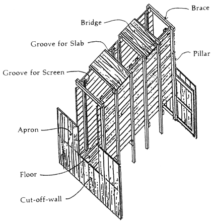
Figure 2. Sample design of a wooden gate (BFAR)
(b) Like the main gate, wooden gates are constructed simultaneously with the construction of the partition dikes. This being easier to construct and install, it may not be necessary to have a temporary dike enclosure. Keep the pond dry by closing the main gate.
The steps in the construction and installation are as follows:
Buy selected lumber and dry it under the shed for at least 15 days.
Establish a control benchmark to check the ground and high water elevation.
Cut lumber according to specifications given in the design.
Assemble the pillars and braces with bronze nails; nail the floor and walls to the pillars and braces. Nail other parts.
Mix coal tar with small amount of cement. Paint the gate with the mixture with at least two coatings. Allow to dry before installation.
Excavate the site to the desired elevation. Check the elevation from the temporary benchmark set for the purpose.
Install the gate at the excavated foundation. Check if properly installed and in the right position.
Fill with mud blocks layer by layer at the sides of the wooden gate. Allow the soil to dry and harden.
Condition the gate by allowing tidal water in and out of the pond.
2.2.5 Dikes in fishpond/tambak
Dikes are structures which enclose or partition the fishpond area for water control and stock separation. These dikes are either a primary or main dike which enclose the area; secondary dikes that divide the rearing ponds or the tertiary dikes which partition the nursery ponds.
These dikes trapezoidal in shape and a cross-section with top width, side slope and the height proportionally designed according to the soil material used. They must be of adequate size and shape to hold water as well as to prevent seepage under or through the dike.
Fishpond dikes constructed with height lower than 4.26 meters should have a side slope of 1:1 while more than 4.26 m a side slope is 2:1.
(a) Design of dikes
The height of dikes are calculated using the following formula:
Main dike

Where:
| Hm | = | Height of the main dike |
| HAT | = | Highest astronomical tide or the the maximum flood water level observed in the locality for at least 10–15 years |
| GS | = | Elevation of the ground surface |
| MF | = | Maximum flood level |
| FB | = | Allowance for free board |
| %S | = | Percent shrinkage and settlement |
Secondary dike

Where:
| Hs | = | Height of the secondary dike |
| HST | = | Highest spring tide |
| GS | = | Elevation of the ground surface |
| MR | = | Maximum rainfall within 24 hours |
| FB | = | Allowance for free board |
| %S | = | Percent shrinkage and settlement |
Tertiary dike

Where:
| Ht | = | Height of the tertiary dike |
| DWL | = | Desired water level |
| GS | = | Elevation of the ground surface |
| MR | = | Maximum rainfall within 24 hours |
| FB | = | Allowance for free board |
| %S | = | Percent shrinkage and settlement |
Figure 3 shows a sample design of the different fishpond dikes.
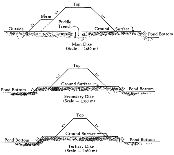
Figure 3. Design of different dikes (BFAR)
(b) Construction of dikes
The first step in the construction is the marking of bamboo stakes the path of the dike. The area is then cleared of vegetation, stumps, debris, etc. For better working space, clearing should be about 2–4 meters wide than the base of the dike.
In building the main dike, a puddle trench, about 50 cm wide and 50 cm deep should be dug in the middle of the cleared path. This, however, may not be necessary for secondary and tertiary dikes. But in the portion of the dike where soil substratum is loose and root-ridden, it is advisable to construct one.
Portions of dike passing dead river beds, creeks, or low places should be constructed first. As much as possible mud blocks for diking should be taken in places near the dike for ease and lower cost. Sand and root-ridden soils are inferior, while sandy clay or clay loam soils are the best diking materials.
When filling mud blocks, the dike should not be raised at once to the desired height. The diking is done in layers allowing each layer to settle before another layer is added. Dike construction may either be done manually or by machine or both.
2.2.6 Canal network in fishpond
Canal network in fishponds are the structures which convey water to the different areas of the fishpond system. Usually the network is about one to two percent of the total area (Figure 4).
(a) Main canal
The main canal starts from the main gate and traverses the central portion of the fishfarm. The canal bed should slope towards the gate but not be lower than the ground elevation of the main gate. Generally, the canal bed has a slope of 1:1 500 or a one meter difference in elevation for a horizontal distance of 1 500 m. A main gate with one meter opening will have a canal bed of at least 3 meters wide. Such width is enough to supply 10–15 hectares. Main canal dikes have a ratio of 1:1 slope.
(b) Secondary supply canal
This is constructed in parts of the fishpond not reached by the main canal. It starts from the main canal and traverses the inner portion of the pond system. It has a bed width of 2.0 meters.
(c) Tertiary canal
This canal is constructed to supply the nursery or transition ponds. This can be used as catching ponds. A tertiary canal has a bed width of 1.0 to 1.5 meters.
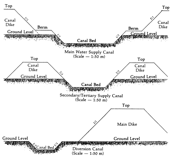
Figure 4. Design of different canals (BFAR)
(d) Drainage canal
Drainage canal in the pond system is constructed to improve water quality and facilitate drying and harvesting. This is located at the other side of the pond, parallel to the supply canal. Drainage canal is necessary for intensive culture, especially in shrimp farms.
(e) Diversion canal
This canal is constructed outside the project to protect the farm from being flooded with run-off water coming from the water shed. It must be strategically located so that run-off water will empty on an established disposal area, natural outlets or prepared individual outlets. The slope of the diversion canal should be in such a way that water flows towards the drainage area.
(f) Construction of the canal
The construction of the canal is done at the same time as construction of the adjacent dikes. Markers should be staked before construction starts. These markers will serve as guide during the excavation of the canals. The canal slope will be the same as the dike. The canal should have a grade sloping towards the main gate. Excavation may be done either manually or by machine or both.
2.2.7 Pond bottom levelling
After completion of the pond system, the next program is pond bottom levelling. This may either be mechanical or manual levelling.
Mechanical levelling is much cheaper and faster than manual levelling if the soil condition will support the equipment. Farm tractors, or tillers, with a back blade may be used. On the other hand, manual levelling is done by slicing the soil into mud blocks and loaded into a sliding board, a bamboo raft, or flat boat to fill up the lower portion of the pond. When completed the pond bottom should slope gently towards the gate. The process in levelling pond are as follows:
Water the pond to the desired elevation and place a wooden marker. Beside the mark, place a meter long gauge calibrated from 0 to 100 cm to serve as levelling guide for cut and fill operation as well as indicate the depth of water inside the pond. Set the gauge in such a way that the zero mark is in the same level with the wooden mark. The zero mark is the required elevation of the pond bottom.
Mark the area of the pond above and below zero elevation marks, then increase the depth of water inside the pond to 40 cm for the flat boat to float.
Excavate the portion of the pond marked above zero elevation. Transport the excavated soil with a flat boat and unload it at the portion of the pond marked below zero elevation. One to two workers should be at the receiving end to supervise the dumping of soil in the deep portion, equipped with a meter stick and from time to time check the elevation of the pond bottom by sounding techniques. If the desired elevation is attained, the receiver transfers to another low area.
When all the marked portions have been excavated, drain the water to zero mark. The remaining soil on the sides can be levelled using spades.
The process is repeated until all low portions are filled. The excess soils are transported to another compartment having low areas or are utilized as berm for the dike or to increase its height.
2.2.8 Construction of equipment
There are two types of equipment, the manually used types and mechanical or heavy equipment; these are as follows:
Hand tools
For excavation
digging blade (sarap)
hoe (pacul)
mud scoop (sorok)
For transport of mud block
bamboo raft (raket)
dugout boat (perahu)
flat boat
For compaction
wooden mallet
coconut trunk
Heavy equipment
Dragline. For dike construction, canal digging and deepening.
Daizer-Crawlers. For levelling provided the load bearing capacity of the soil can support the weight of the equipment.
Hydraulic excavators, backhoe, shovels, cranes, payloaders. These can also be used to advantage in tambak projects.
Scrapers, dump trucks, wheel-type loaders. These can also be used effectively where soil conditions permit.
2.3 Fishpond layout plan
The layout and plan of a fishpond project depends on the land configuration and elevation in relation to the source of water and drainage. A sample layout is shown in Figure 5.
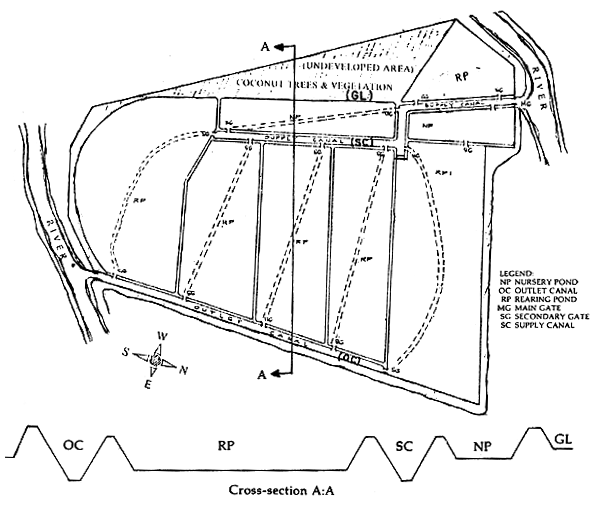
Figure 5. Proposed layout plan for a one-hectare semi-intensive shrimp pond
REFERENCES
Direktorat Jenderal Perikanan. 1987 Statistik Perikanan Indonesia 1985. Direkt. Jenderal Perikanan, Deptan, Jakarta.
dela Cruz, C.R. 1983 Fishpond engineering: A technical manual for small- and medium-scale coastal fish farms in Southeast Asia. SCS Manual No. 5: 180p.
Esguerra, R. S. 1977 The layout, construction and management of brackishwater fishponds in the Philippines. Joint SCSP/ SEAFDEC Workshop Aquaculture Engineering, Tigbauan, Iloilo, Philippines. SCS/GEN/77/15: 197–206p.
Hechanova, R. G. and B. Tiensongrusmee. 1980 Report of assistance on selection of site, design, construction and management of the Ban Merbok, Kedah, Malaysia Brackishwater Aquaculture Demonstration Project. SCS/80/WP/ 88: 154p.
Kontara, E.K., B.S. Ranoemihardjo, S. Saimun and M. Adijaya. 1986 Tehnik budidaya udang windu (Penaeus monodon). BBAP, Direkt, Jenderal Perikanan, Deptan, Jakarta. INFIS Manual Seri No. 29: 23p.
Ranoemihardjo, B.S., S. Saimun, 1986 A. Sunaryanto and A.F.M. Soni. Konstruksi dan pembangunan tambak. BBAP, Direkt. Jenderal Perikanan, Deptan, Jakarta. INFIS Manual Seri No. 5: 24p.
Yamashita, M. and Sutardjo. 1977 Engineering aspects of brackishwater pond culture in Indonesia. Joint SCSP/SEAFDEC Workshop Aquaculture Engineering, Tigbauan, Iloilo, Philippines. SCS/ GEN/77/15: 261–280p.
ACKNOWLEDGMENT
The author is grateful to Mr. Rodolfo C. Pinto for technical editing of this material and to Mrs. Medina N. Delmendo, Project Coordinator, RAS/84/016, for suggestions and comments.
by
Iin S. Djunaidah Brackishwater Aquaculture Development Centre Jepara, Indonesia
1. INTRODUCTION
One of the main problems in shrimp culture is the limited supply of shrimp fry to stock in grow-out ponds. Although in certain areas they are available from the coastal waters, the quality is unpredictable and availability is seasonal.
For better shrimp culture production and management, continuous supply of fry is required so that building a shrimp hatchery to produce postlarvae is necessary.
Hatchery technology has evolved into a number of different methods which can be categorized into three methods, such as extensive method or “Japanese method”, intensive method or “Galveston method”, at Jepara, Indonesia, the semi-intensive system is being used.
The Brackishwater Aquaculture Development Centre (BADC) in Jepara, Indonesia has been successful in inducing the farmraised shrimp, the Penaeus monodon or Penaeus merguiensis to spawn in the broodstock tank by eyestalk ablation. It was initially done in 1978 which made a new dimension in stimulating the expansion of shrimp culture programme in Indonesia.
Indonesia has about 200 000 hectare of brackishwater ponds in operation.
2. BIOLOGY OF PENAEUS MONODON
Wild gravid Penaeus monodon females spawn in the open sea. It takes about two weeks from hatching of the eggs through the planktonic larval stages until the postlarval stage. Benthic post larvae are found along the coast or in mangrove swamps and other estuarine areas where they are collected by fry gatherers for rearing in brackishwater ponds up to marketable size. Wild fry become juveniles and adults in estuarine areas but return to the sea for spawning.
After spawning, it takes about 12 to 15 hours for P. monodon eggs hatch to the nauplius stage. There are six nauplius substages (N1-N6) that molt five times within 48 to 56 hours. The next stage is Zoea which undergoes substage (Z1-Z3), all of which are completed within 5 to 6 days. The next and last larval stage is the Mysis which has three substages (M1-M3), it is completed in 4 to 5 days. In this stage, they are stocked in nursery ponds until PL15-PL20 when they are ready for stocking in grow-out ponds. Figure 1 shows the life cycle of the shrimp from egg to postlarval stage.
3. PHYSICAL FACILITIES AND EQUIPMENT IN SHRIMP HATCHERY
3.1 Seawater supply system
The hatchery should have a good seawater source with a salinity range of 30–35 parts per thousand (ppt) and free from agricultural and industrial pollution. Seawater can be pumped to the hatchery either direct from the sea or from an inshore well (Figures 2 and 3). To reduce turbidity, eliminate debris and undesirable organisms such as fish eggs and larvae, the seawater prior to actual use passes through a filtration system made of layers of sand and graded gravel (Figure 4).
3.2 Aeration system
Aeration system is necessary to provide oxygen in the water, keep larvae and food in suspension. This should be so designed for a non-stop operation. The roots type blower have been found to give reliable service. A network of PVC pipes is used to provide air to the different tanks in the hatchery.
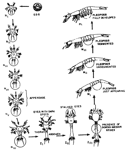
Figure 1. Larval stages of prawn (From Motoh, 1979)
3.3 Larval and postlarval rearing tank
Hatchery tanks vary in size from 1 to 20 tons capacity. For economy and ease in operations, larval rearing tank should have water holding capacity of 3 to 5 tons. For postlarval rearing tank, 6 to 10 tons. Both tanks have a minimum depth of one meter.
These tanks may be made of concrete fiberglass, marine plywood or bamboo with plastic lining. The shape may either be circular, rectangular or square, with bottom sloping towards the outlet for easy draining and collection of stock (Figure 5).
3.4 Maturation tank
The major problem in hatchery operation is the limited supply of spawner from the wild. Hence, eyestalk ablation technique of mature shrimp has to be done to stimulate the spawners. The ablated shrimp is stocked in maturation tanks to develop and to ensure a continuous supply of gravid female.
The shape of the tank can be circular, rectangular or oval with water holding capacity from 5 to 40 tons. Water depth from 1.2 to 2 meters (Figure 6).
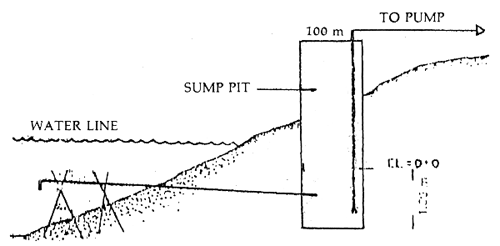
Figure 2. Pumping from a sump pit
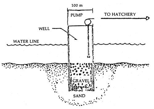
Figure 3. Pumping from inshore well
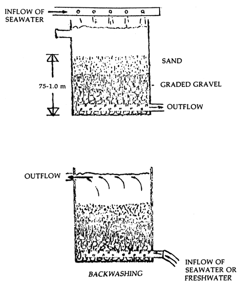
Figure 4. Cross-section of a sand and gravel filtration unit
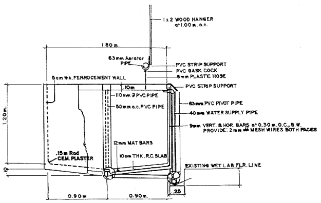
Figure 5. Cross-sectional detail of 2.5 tons ferrocement larval rearing tank1
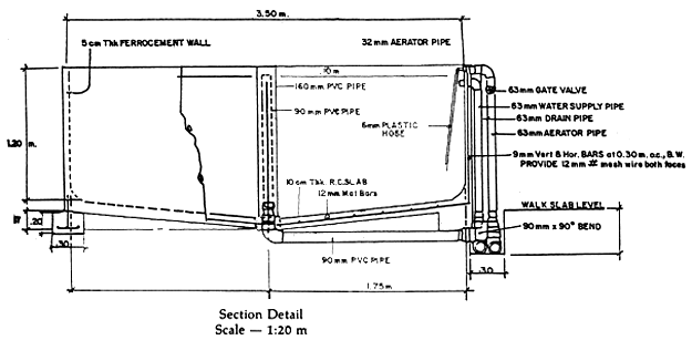
Figure 6. Cross-sectional of 12 tons ferrocement broodstock tank1
1 From NACA Technology Series No. 4, 1986.
3.5 Spawning tank
This tank may be made of fiberglass, plexiglass, plastic or marine plywood. It is circular in shape, flat or conical bottom water holding capacity range from 50 liters to 1.5 tons (Figure 7).
3.6 Algae culture tank
Algae culture tanks may be made of fiberglass, polyethylene or marine plywood. The tank capacity ranges from 1 to 20 tons. The algae culture tank capacity is about 10 to 20 percent of the total capacity of the larval rearing tanks (Figure 8).
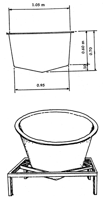
Figure 7. A 250-liter fiberglass spawning tank 1
1 From: NACA Technology Series No. 4, 1986.
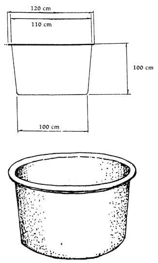
Figure 8. A 1-ton fiberglass tank utilized for algae culture1
1 Form: NACA Technology Series No. 4, 1986.
3.7 Water storage tank
It is a must that a hatchery should have a water reservoir to facilitate the changing of water when needed. The water storage tank should have a water capacity of 30–50 percent of the maximum total water use for the day. This has to be elevated to allow water to flow by gravity for distribution to all the tanks.
3.8 Building
A not so expensive building is necessary to protect the hatchery facilities as well as the cultured organisms from extreme weather condition. This could be made from locally available materials such as nipa, bamboo or coconut lumber. The building should also provide for quarters technicians who monitor the activities in the hatchery.
4. MANAGEMENT PRACTICES
4.1 Preparation of tanks
Of the several activities in hatchery operations, the most important is the preparation of the tanks prior to culture. The tanks must be cleared, sterilized and disinfected with 12 percent hypochloride solution at a rate of 200 ppm for 24 hours and then exposed to sunlight for one day before stocking. Once ready, the tanks are filled with filtered seawater to the desired level and the necessary aeration system is introduced.
4.2 Care for spawners
The normal weight of spawners ranges from 90 to 200 g. Males are usually smaller than females and become sexually mature at 75 g.
The spawners may come from the sea, collected by fishermen through trawl or gill net fishing and from grow-out ponds in which shrimps are induced to maturation by eyestalk ablation.
Ablated female shrimps are stocked in maturation tanks with 1:2 male-female ratio. Feeds are chopped or ground squid, meat, mussel, shrimp, etc. given at 15 percent total body weight per day.
The monitoring of gonad maturation is done 1–2 weeks after stocking. Once the gonad is at stage III, the shrimps are transferred to the spawning tanks.
4.3 Spawning and hatching practices
Gravid female shrimps are placed in the spawning tank provided with aeration and filtered seawater with salinity of 30–35 ppt and at temperature of 26–30°C. Usually, spawning takes place about 10:00 P.M. and 4:00 A.M. in the morning.
As evidence of spawning, the presence of pink orange scum on the water surface and walls of the tank is noticeable.
After spawning, the spawners are collected in the morning and transferred to a recovery tank.
Hatching takes place after 12–18 hours after fertilization at a temperature of 26–30°C and salinity of 30–35 ppt.
The nauplii are counted and transferred to larval rearing tanks.
4.4 Larval rearing
The term larvae applies to the nauplii to mysis stage. From the spawning tank the nauplii are transferred to the larval rearing tank at a rate of 50–100 nauplii/liter.
The nauplii at stage VI are fed with live phytoplankton. Tetraselmis chuli, Skeletonema costatum and Chaetoceros sp. are usual feeds for shrimp larvae. The nauplii of Artemia salina are given at the mysis stage. Artificial feeds are also given in addition to live feeds.
In order to maximize feed utilization, feeding technique is adjusted according to the need of the larvae. Live feeds are given two times a day while artificial feeds are given five times a day (Table 1). Algal levels are determined with the use of the haemacytometer.
Table 1. Kinds and quality of feed used for shrimp larval rearing at BADC, Jepara
| Stage | Live Feed | Artificial Feed Size (m) | ||
|---|---|---|---|---|
| Plankton cells (cc/day) | Artemia nauplii (pc/day) | Amount (mg/pc/day) | ||
| Zoea | (5–20) × 103 | - | 0.07 | 10–60 |
| Mysis | (20–30) × 103 | 15 | 0.10 | 60–100 |
| Postlarvae | - | 30 | 0.14 | 105 |
4.5 Maintenance of good water quality
To maintain good water quality in the larval rearing tanks, the changing of water and removal of uneaten feed regularly is necessary. The water quality should be monitored either through laboratory analysis or visual observation. Typical sign for poor water quality are water cloudiness and stale odor.
During the larval rearing, the health, population and stage of development have to be monitored regularly. This will help in the determination of feed to be given daily. To study the conditions, at least 15 pieces of the animal should be examined in the microscope daily. Record keeping is also a must for hatchery operation. Recorded data will help future operations.
4.6 Harvesting
From the larval stage, the shrimp fry is ready for harvest when it is at postlarvae stage, PL1–5. The postlarvae are either transferred to concrete or earthen pond or in nursery cage. The postlarvae are then grown to postlarvae 15–20 when they are ready for stocking in grow-out post.