These are channels for receiving and conducting run-off water to a safe or protected area with a minimum of erosion. The shape of a waterway can be parabolic, trapezoidal, rectangular or triangular (V-shaped). It is usually protected by either vegetation or engineering structures, or a combination of both.
Criteria for selection
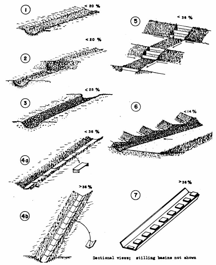
Grass waterways can only be used on slopes of less than 20% and where flow velocities do not exceed 1.8 m. Other types of waterways should be used on steeper slopes and where there are higher flow velocities. Table 8 shows the major types of waterways, their uses and limits. See Fig. 19 for their corresponding diagrams.
- To drain excess run-off from a terraced field or a conservation-treated area.
- To carry water downslope to a safe or protected area.
- To minimize erosion from concentrated run-off.
- Where rainfall intensities are high and excess run-off is frequent, such as slopes in humid regions.
- In semi-arid or arid regions where soil infiltration rates are low and run-off is concentrated.
- Where cultivated fields have been treated with various types of terracing systems and drainage is necessary.
- On non-cultivated lands to connect run-off drainage structures such as diversions, cut-off ditches, gradoni, etc.
Channels
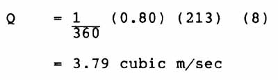
Shape As stated earlier, channels can be parabolic, trapezodial or triangular-shaped (Fig. 22). The appropriate shape is determined by the site conditions, slope, available tools, and construction methods. For instance, on gentle slopes, it is easier for a tractor, fitted with a blade, to make a traingular channel but its shape may be inconvenient for occasional crossing by wheeled vehicles. The parabolic-shaped channel requires extra time for shaping but it results in a smoother water flow. Unlike a trapezodial-shaped channel, it will not easily erode the corner of the side slopes. However, on very steep slopes where chute structures are required, the triangular type is much better for confining the flows and is also easy to build.
Length: As long as the flows are within the safe velocity limit (see next section on velocity) the length of a channel is usually determined by the farmer's needs and terrain conditions. When velocity exceeds the safe limits, drop structures, low check dams or basins are needed to slow down the flow on moderate slopes, it is recommended that low dams and drop structures be set up every 30 to 40 m to slow down the flows in grass waterways.
Width and depth: The correct width for a channel depends on the quantity of water, slope, and land available. On large cultivated fields, grass waterways with a width of 20 to 60 m, or more, are not uncommon. However, on small farms in developing countries, the waterways are usually 1 to 2 m wide.
The deeper the channel, the more inconvenient the field operation and maintenance will be. Deeper channels also result in higher velocities and pose problems for people crossing them. Both the width and depth of a channel can be adjusted by trial and error for the safe drainage of runoff to accommodate the designed flows within the recommended velocity limits (Appendix 2). A freeboard of 10 to 20 cm should be added for safety purposes.
Sites: Natural depressions are normally used for waterway sites but they need to be
properly shaped and protected. If no such places are available, then waterways are best
established close to the field boundary in order to minimize interference in field
operation. However, a waterway can be established in the middle of the field if there is a
good outlet or protected areas downslope.
Cross-sections: Fig. 22 shows the formulas for calculating the cross-section area for the
various waterways. The cross-section
should be a little larger than the minimum through which the peak run-off can pass at a
safe velocity.
Estimation of run-off
Rational Formula: There are several methods for estimating peak run-off but the rational formula is the simplest one to use.
The formula for the metric system is as follows:
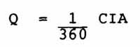
Q : peak run-off, in cubic m/second
C : run-off coefficient, the % of rainfall appears as run-off
I : maximum intensity for a given frequency in a duration equal to the time of concentration, in mm per hour
A : area of watershed, in ha.
Run-off coefficient: The run-off coefficient "C" varies according to rainfall, vegetation, slope and soils. It should be determined locally by experience, observations and experiments. However, Table 9 shows some C values for reference purposes.
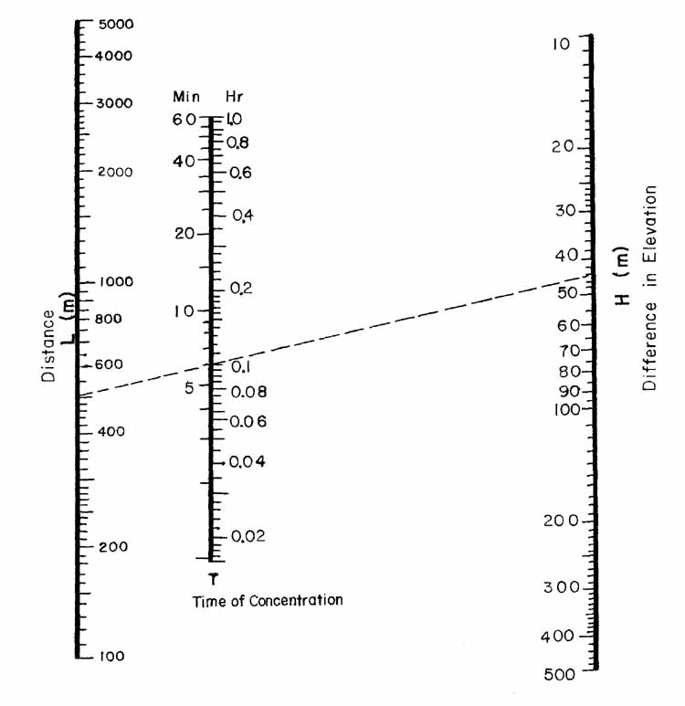
Example:
Given :
L = 500 m
H = 44 m
Find = Time of concentration
Solution: Draw a straight 'Line from L axis (500) to H axis (44). -The line intercepts one point at T axis. This is the answer: 0.1 hr or 6 min
1 . Formula
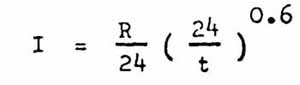
Where :
I: rainfall intensity, in mm/hr
R: maximum daily rainfall of 10 year return period, in mm
t: time of concentration, in hr
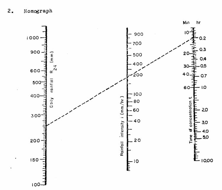
Example
Given: R24 = 250 mm (9-8 in)
t = 12 min or 0.2 hr
Find rainfall intensity figure for 12 min
Solution Drawing a straight line as it intercept at 183 mm/hr This is the answer
Maximum rainfall intensities: The factor "I" consists of two parts, time of concentration and maximum rainfall intensities.
The time required to concentrate run-off depends mainly on distance of flows, elevation differences and the size, shape and ground conditions of a watershed.
Fig. 20 shows the Kirpich's Nomograph for estimating time of concentration, using mainly flow distances and elevation differences. It applies to small agricultural watersheds. When there are no data or maps on elevation difference and distance and when the watershed sizes are known, Table 10 can be used for reference.
The maximum rainfall intensities for various durations can usually be obtained from the national meteorological service or from a local agricultural or forestry recording station. As explained earlier, data on rainfalls over a 10-year return period are sufficient when designing waterways. Table 11 shows intensity figures used in Jamaica and they may be applicable to many humid tropical countries with similar conditions. Fig. 21 shows a nomograph used in Taiwan(Province of China), produced from a formula using maximum daily rainfall. This nomograph can be used as a reference for countries in which short duration rainfall intensities are lacking.
Example: Calculate the designed peak flow using Tables 9, 10 and 11 for building a waterway at the outlet of a 8 ha cultivated field under tropical conditions:
- Using Table 9, the C value under tropical conditions, is 0.80
- Using Table 10, the time of concentration is about 5 minutes
- Using Table 11, the corresponding intensity per hour is 213 mm
Thus, the peak run-off can be obtained as follows:
Velocity
Limits: The approximate velocity limits for safe flows in a protected waterway are as follows:
Grass waterways 1.8 m/sec
Ballasted stone waterways 3.0 m/sec
Concrete and masonry waterways 6.0 m/sec
Fig. 22. Typical cross-section of waterways and formulas for calculations.
Estimation of velocities
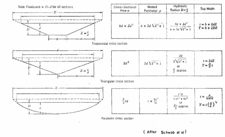
Manning Formula: The Manning Formula is normally used to calculate average velocities in a channel. The velocities calculated should not exceed the recommended safe limits. The formula is shown below:
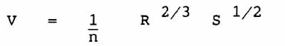
V = average velocity of flow, in m/sec
n = roughness coefficient of the channel
R = hydraulic radius, equal to the cross sectional area divided by the wetted perimeter
(A/P), in m
S = hydraulic gradient (slope channel), in %
The dimensions of the channel should be uniform and their relation to the velocity should be as follows:
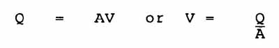
V = velocity, in m/sec
Q = quantity discharge, in cubic m/sec
A = cross section area, in square m
Roughness coefficient (n): Table 12 shows the roughness coefficient (nvalues) in the Manning Formula. For protected waterways or diversions, many of the n-values are readily useful.
Hydraulic radius (R): R-value is equal to the cross-sectional area (A) divided by the wetted perimeter (P), as explained before. Fig. 22 shows the formulas used to obtain R-values of three different shaped waterways.
Sample calculations and cross-section determination: Appendix 2 shows sample calculations for a narrow parabolic grass waterway on a small farm. The drainage area is 0.5 ha and the slope is 18%. The calculations show, step-by-step, how to discover an ideal waterway cross-section at a non erosive velocity.
Additional tables and nomographs: Fig. 23 is a nomographic solution of Manning's Formula on slopes up to 20%. An example is given.
Table 13 shows the discharge for small parabolic grass waterways of different sizes and gradients. This can be used to determine the correct cross-sections of grass waterways on moderate slopes.
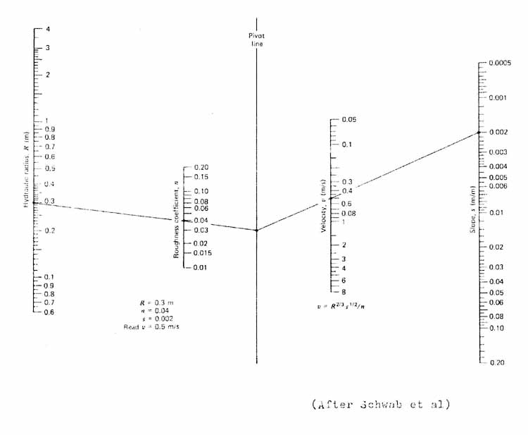
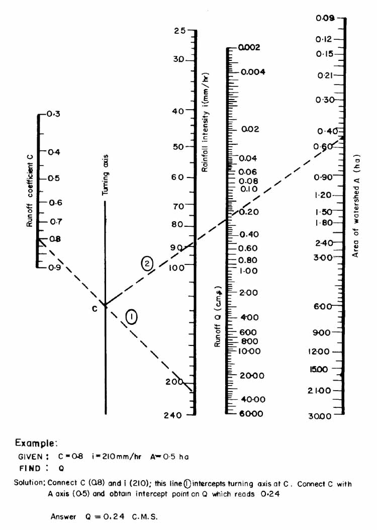
The nomograph in Fig. 24 can be used for a quick estimation of run-off for small
watersheds.
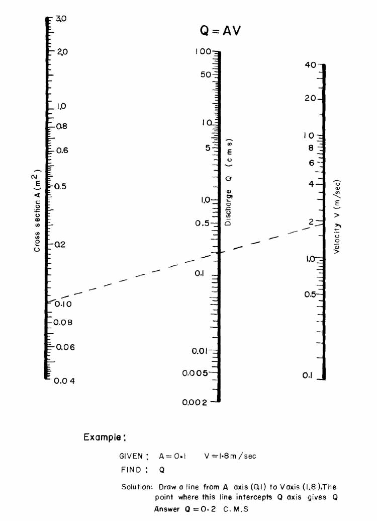
Fig. 25 is a nomograph used in conjunction with the formula Q AV. It can be used for
designing the weirs or notches of structures.
Fig. 24. Nomograph for estimation of run-off for small watersheds.
Structures Drop structures, check dams, chutes or prefabricated structures (Fig. 19)
are generally used in steep channels for
protection and/or for slowing down flow velocities. While the design principles of these
structures can be obtained from other volumes in the series (Gully Control and Torrent
Control), the following points need to be briefly explained here:
Drop structure: These consist of
- A main wall to hold the earth in place
- A weir at the top to allow run-off to flow over. The correct cross-section of the weir can be calculated by the previously mentioned formula, Q = AV, or using a nomograph (Fig. 25)
- Two wing walls to confine the run-off and to strengthen the structure
- A cut-off wall at the bottom to prevent seepage
- A stilling basin with an apron and sill to dissipate the energy of the falling water. Length should be 1.5 to 2 times the height of the water fall.
Small check dams: Similar to drop structures except they are usually built without wing walls. However, the main walls should be firmly keyed in the side banks. The main wall should be sloped toward the weir to reduce the danger of erosion of the banks should an unexpected flow occur. The weirs must be sufficiently large to accommodate peak flows.
Chute: This is a channel for steep slopes and is used to convey run-off from an elevation to a lower point. The cross-section can be V-shaped (90 degrees), trapezodial or rectangular. The structure may be concrete, masonry or partly grassed. Cut-off walls are needed at intervals. Like drop structures, a stilling basin or apron is required at the bottom end of the chute.
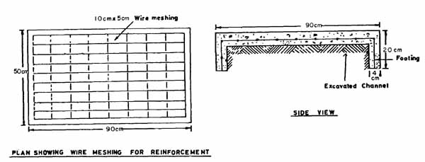
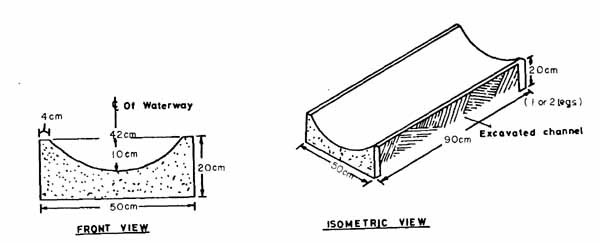
Prefabricated structures: These are ready-made portable concrete structures which, owing to their small size, can be used for rapid installation in a pre-dug channel. They are recommended for steep sites in humid countries where the rains are sufficiently frequent to interfere with normal construction work. To install them, only a little mortar is needed under the slabs and to join their bases. The shape of the structures can be V-notch or parabolic; Fig. 26 shows the specifications of the latter type.
Included above.
The elevation of the waterway should be slightly lower than any drainage or terrace outlets. All the outlets must be connected to the waterway which should be laid out as straight and as uniformly as possible. Small structures or basins should be laid out at regular intervals in long grass waterways or on sites where changes of direction or slope are unavoidable. Choose a well protected area at the low end of a waterway for the safe discharge of flow.
Waterway widths should be properly staked out and when shaping by hand, cord or ropes can be used to line up the edges. An arched wooden bamboo frame marked with the actual dimensions of the channel can be employed for precise shaping.
Shaping: The waterway channel should be shaped as evenly as possible. Any sudden falls and sharp turns must be eliminated except in areas where a structure is planned. The channel grade should be shaped according to the design plan. Stones and stumps which could interfere with the flow must be removed.
Grass planting: Where possible, local species should be used for seeding or planting. Sod-forming or rhizome grass is preferable to tall bunch-type grass. Seeding is cheaper than sodding especially in the case of large waterways. For protection purposes, the seeded area needs to be mulched. After planting grass, the waterway should not be used for a while so as to prevent the seedlings from being washed away by concentrated run-off. During this period, the run-off should be diverted to another outlet.
Ballasting: This practice can be employed where rocks are available on sites where the waterway gradient is too steep for grass protection. It is particularly recommended for waterways on small farms. The diameter of the rocks should be at least 15 to 20 cm and they must be set firmly in the ground. Wire mesh is sometimes used as ballasting on very steep slopes. Partial ballasting in the centre of parabolic channels, leaving the sides with grass protection, has proved a cost-effective technique.
Structures: It is essential that the structures be built strong enough to successfully handle the designed flows. The water must go over them and not under or around them. The structures should be built on cut and firm soils and have strong, deep foundations. Steel bars or wire mesh are needed for chutes and for tall drop structures built with cement blocks. The aprons or stilling basins should be sufficiently strong and large to absorb the energy or impact of the falling water. Enough good quality mortar should be used to ensure that the structures are watertight.
After construction, the earth around the structure should be pressed down firmly to prevent it from cracking or settling. Sodding should then be carried out at the junctures of the earth and the structure in order to prevent tunnelling.
The earth-moving operation is similar to that for hand-built diversions and trenches (2 to 3 cubic m per man-day) and to that for machine-built broadbase channels. The cost of the structures depends upon the cost of cement, materials and local wages. Table 14 shows some cost figures and man-day requirements in two countries for waterways per ha (approximately 100 m in length).
Generally speaking, the most economical way of dealing with run-off is to use natural vegetated areas as outlets. If run-off must be concentrated, grass waterways are much cheaper than those using structures or ballasted stones. In turn, ballasted waterways, especially centre-ballasted ones, are cheaper than using structures or prefabricated structures. On moderate slopes, grassed waterways which have drop structures at regular intervals to slow down flow velocities are more cost effective than waterways built with an overall structure such as a chute.
When run-off is concentrated on steep slopes, the use of prefabricated structures in the middle of the channel to carry normal flows, leaving the two sides protected with grass to take care of occasional heavy flows, is more cost-effective than constructing overall structures in concrete or masonry. However, waterways protected by concrete or masonry structures will be cost effective if they can also be used as a foot path (Fig. 19).
The outlets of a waterway should be safe and open so as not to impede its free flow. Grass waterways should not be used as foot paths, animal tracks, or as grazing grounds. Frequent crossing of the waterways by wheeled vehicles is not recommended.
Newly established waterways should be kept free from disturbances. On sites with large waterways, protecting with fencing is worthwhile. The waterways must be inspected frequently during the first two rainy seasons after completion. Any minor breaks in the channels or structures should be repaired immediately. Bushes or large plants which could endanger the growth of grass must be removed. The grass of the whole waterway should be kept as low and as uniform as possible to avoid turbulent flows. Finally, it should be remembered that waterways form an integral part of watershed conservation or land treatment systems. If they fail to achieve their objectives due to lack of good maintenance their concentrated flows can create gullies.
| Type | Shape | Channel Protection | Velocity Limit | Slope Limit | Uses |
| 1. Grassed Watarway | Parabolic | By grass | 1 . 8 m/sec (6'/sec) |
< 11� (20%) | For new waterway or uniform sloped depression |
| 2. Grassed waterway with drop structures | Parabolic | By grass and concrete or masonry structures | 1.8 m/sec (6'/sec) |
Between two structures: 3%, overall slope <11� (20%) |
For discontinuous type of channel |
| 3. Ballasted waterway | Parabolic | By stones or by stones and wire mesh | 3 m/sec (10'/sec) |
<15� (26%) | Where stones are available |
|
4. Prefabricated concrete waterway
|
A stalling basin is usually needed at the end | ||||
| a. Parabolic waterway | Parabolic | By concrete structures and grass | 6 m /sec (20'/sec) |
< 20� (36%) | Where rainfalls are frequent and flows are constant |
| b. V-notch chut c | 900 V-notch | By concrete structures and grass | 6 m /sec (20'/sec) |
>20� (36%.) | Same as above and on very steep slopes |
| 5. Stepped Waterway | Parabolic and rectangular | By grass and concrete or masonry drops | On grass part, 1 .8 m/sec (6'/sec) |
Overall slope <20� (36%) |
For 4-wheel mechanization and in the middle of bench terraces |
| 6. Waterway and road ditch complex | Parabolic | By grass and stone ballasting | 3 m/Bee (10'/sec) |
8 � (14%) | For tractor crossing and 4-wheel mechanization |
| 7. Chute complex | Trapezoid or rectangular | By concrete or masonry structure | 6m/sec (20 ' /sec) |
>20� (36%) | For paths on small farms and on very steep slopes |
These limits are approximations for general reference. In practice, the volume and velocity of runoff and site conditions should all be taken into consideration for determining the type of waterway needed. Most of these types of waterways handle a few hectares of runoff.
|
Climate Zone |
Land Use |
C-value | |
| Rollin2/ | Hilly3/ | ||
| 1. Temperate & less humid1/ | Cultivated | 0.60 | 0.72 |
| Pasture | 0.36 | 0.42 | |
| Forestry | 0.18 | 0.21 | |
| 1/U.S.A. figures, | |||
| 2/From 5 to 10% slope | |||
| 3/From 10 to | |||
|
Hilly Lands |
|||
| 2.Tropical & humid 4/ | Cultivated | 0.80 5/ | |
| Fallow lands | 0.55 | ||
| Scattered woodlands and food forest | 0.45 | ||
| good grasslands | 0.5 | ||
| Dense forest | 0.30 | ||
| 4/ Jamaica figures used in hilly watersheds | |||
| 5/ Taiwan uses the value of 0.85 | |||
|
Area
|
Time of Concentration (Min) | |
|
Ha
|
Acre
|
|
|
0.4
|
1 |
1.4
|
|
2
|
5 |
3.5
|
|
4
|
10 |
4.0
|
|
8
|
20
|
4.8
|
|
20
|
50 |
12.0
|
|
40
|
100 |
17.0
|
|
200
|
500 |
41.0
|
Remarks:
1/ The figures are from U.S.A (Ayres)
2/ Channel gradient 5%
3/ Above figures may have to be adjusted according to local conditions
|
Duration |
Rainfall all |
Intensity |
||
|
(Min)
|
mm |
in.
|
mm/hr |
in/hr |
|
5 |
17.8 |
0.7 |
213.4
|
8.4
|
|
10 |
30.5 |
1.2 |
182.9
|
7.2
|
|
15 |
40.6 |
1.6 |
162.6
|
6.4
|
|
20 |
50.8 |
2.0 |
152.4
|
6.0
|
|
30
|
63.5 |
2.5 |
127.0
|
5.0
|
|
60 |
83.8 |
3.3 |
83.8
|
3.3
|
Remarks:
1/ 10-year return period
2/ The above figures are first approximation
|
n Values |
||
| Type, and Description of Ditches |
Range
|
Mean
|
| Earth ditch | ||
| Clay soil, straight and uniform |
0.016-0.022
|
0.020
|
| Sandy loam or clay loamy straight |
0.020
|
|
| And uniform | ||
| Loosely grassed |
0.035-0.045
|
0.040
|
| Densely grassed |
0.040-0.060
|
0.050
|
| Mixed pebbles from 1 to 3 em in Diameter |
0.022
|
|
| Mixed pebbles from 2 to 6 em in Diameter |
0.025
|
|
| Smooth, homogeneous stony bed |
0.030-0.035
|
0.033
|
| Rough stony bed |
0.035-0.045
|
0.040
|
| Lined ditch | ||
| Paved brick |
0.012 - 0.017
|
0.014
|
| Paved rubble stone |
0.017-0.030
|
0.024
|
| Rubble stone |
0.025-0.035
|
0.030
|
| Uniform earth bottom, rubble sides |
0.025
|
|
| Rough earth bottom, rubble sides |
0.028-0.035
|
0.032
|
| Cement paved, smooth sides and Bottom |
0.010-0.014
|
0.012
|
Note: This table can be used for waterways, diversions, or other channels.
|
Width of Waterway |
Depth of water d(m) |
Gradient of waterway bottom (%) (unit: c.m.s) | |||||||||||||||
|
0.1
|
0.5 |
1
|
2
|
3 |
4
|
5
|
6 |
||||||||||
|
1 |
0.10
|
0.013 |
0.029 |
0.041
|
0.057
|
0.069 |
0.081 |
0.089 |
0.097 |
||||||||
|
1.2 |
0.14
|
0.032 |
0.073 |
0.101
|
0.141
|
0.172 |
0.204 |
0.224 |
0.244 |
||||||||
|
1.4 |
0.18
|
0.067 |
0.148 |
0.208
|
0.293
|
0.353 |
0.417 |
0.459 |
0.501 |
||||||||
|
1.6 |
0.22
|
0.118 |
0.270 |
0.377
|
0.529
|
0.642 |
0.754 |
0,828 |
0.906 |
||||||||
|
1.8 |
0.26 |
0.202 |
0.446 |
0.632
|
0,884
|
1.069 |
1.263 |
1.389 |
1.507 |
||||||||
|
2.0 |
0.30 |
0.312 |
0.696 |
0.984
|
1.380
|
1.680 |
1-980 |
2.172 |
2.364 |
||||||||
|
2.2 |
0.34 |
0.477 |
1.037 |
1.465
|
2,058
|
2.502 |
2.946 |
3.226 |
3.522 |
||||||||
|
2.4 |
0.38 |
0.679 |
1.489 |
2.101
|
2.933
|
3.568 |
4.203 |
4.619 |
5.035 |
||||||||
|
2.6 |
0.42 |
0.937 |
2.073 |
2.896
|
4.06
|
4.940 |
5.820 |
6.388 |
6.956 |
||||||||
|
2.8 |
0.46 |
1.262 |
2.777 |
3.931
|
5.481
|
6.635 |
7.825 |
8.618 |
9.376 |
||||||||
|
3.0 |
0.50 |
1.665 |
3.645 |
5.175
|
7.200
|
8.775 |
10.305 |
11.340 |
12.375 |
||||||||
|
Width of waterway t (m) |
Depth of water d (m) |
Gradient of waterway bottom |
|||||||||||||
|
7
|
8
|
9 |
10
|
12.5 |
15 |
17.5 |
20
|
||||||||
|
1 |
0.10 |
0.105 |
0.113 |
0.122 |
0.130
|
0.142 |
0.158 |
0.170 |
0.182
|
||||||
|
1.2 |
0.14 |
0.265 |
0.285 |
0.305 |
0.325
|
0.356 |
0.396 |
0.426 |
0.457
|
||||||
|
1.4 |
0.18 |
0.540 |
0.582 |
0.625 |
0.667
|
0.731 |
0.812 |
0.875 |
0.939
|
||||||
|
1.6 |
0.22 |
0.980 |
1.058 |
1.132 |
1.205
|
1.323 |
1.469 |
1,582 |
1.700
|
||||||
|
1.8 |
0.26 |
1.633 |
1.760 |
1.886 |
2.012
|
2.026 |
2.459 |
2.644 |
2.829
|
||||||
|
2.0 |
0.30 |
2.568 |
2.760 |
2.964 |
3.156
|
3.456 |
3.852 |
4.140 |
|||||||
|
2.2 |
0,34 |
3.619 |
4.115 |
4.411 |
4.708
|
5.136 |
5.720 |
||||||||
|
2.4 |
0.38 |
5.451 |
5.867 |
6.282 |
6.698
|
7.333 |
|||||||||
|
2.6 |
0.42 |
7.552 |
8.120 |
8.716 |
9.284
|
||||||||||
|
2.8 |
0.46 |
10.169 |
10.962 |
11.756 |
12.513
|
||||||||||
|
3.0 |
0.50 |
13.410 |
14.445 |
15.480 |
|||||||||||
Note :
1/ The Figures above or the left of that heavy lines are within the permissible range
2/ If a calculated run-off (Q) is bigger than the corresponding- figures in the table, it means the cross-section is not big enough. Therefore, it needs to look for a bigger channel.
| Type of Waterway | Site | Mondays & Material | Cost |
| El Salvador +/ | U.S.$ | ||
| Grass waterway | On 12% | 18.3 m/d |
22.0 |
| 1.5 m wide | slope | only | |
| Prefabricated | On 21% | 32.0 m/d |
160.0 |
| waterway (parabolic) 1.5 m wide | slope | plus material | |
| Stepped waterway | On 25% | 51.0 |
252.0 |
| (f or mechanization) 1.5 m wide | slope | plus material | |
| Jamaica ++/ | |||
| Centre Ballasted | On 42% | 34.0 m/d |
122.0 |
| waterway 1.2 m wide | slope | (including, collection) |
+/ Local wage at US$1.2 a man-day in 1976
++/ Local wage at US$3.6 a manday in 1984
![]()
![]()
![]()