![]()
![]()
![]()
JEAN LE RAY
II - Construction works, use and maintenance of equipment
CLEARING is the first phase in the construction of forest roads. The work is complicated by the fact that the great tropical forests consist of several stories of vegetation and trees of every diameter. As a rule the work is carried out in several stages either by a bulldozer-tractor working on its own, or by a bulldozer preceded by gangs who at least partially fell the forest. Let it be assumed that a bulldozer of 130 to 160 nominal horsepower (standard makes such as D7HD 16-TD 15-CD 8) is being used.
The alignment is generally marked out on the ground by a line marked by stakes and slashed to a width of 2 meters, but sometimes it is shown by a clearing 10 meters wide, which is intended to guide the tractor operator. Along this strip the creepers, shrubs and saplings up to 10 centimeters in diameter are cut down. This strip corresponds to the width of the proposed road reserve.
The crew of the tractor generally consists of three men; the operator, and two assistants who help to maintain the tractor and to adjust the blade of the angledozer or tiltdozer. The assistants' principal function, however, is to cut down the creepers obstructing the operator, pull off branches which get caught in the radiator or round the tracks and more particularly to cut back the roots protruding from the earth and to slip the winch cable over the stumps.
PRINCIPLES OF CLEARING
There are two methods:
1. To cut down, with an axe or a chain saw, all the large and small trees to a height of 1 to 2 meters above the ground and then remove the stumps with a bulldozer.2. To attack the forest in the first place with a bulldozer which clears a way for itself through the vegetation.
First method
Clearing is done in two stages: felling and then uprooting. Hand felling by means of axes or saws can be considered as a waste of man power. (It is of course the traditional and time-honored method of forest people in preparing plantations for food crops.) This preliminary felling can be of all the trees, or of only the larger ones with a diameter of more than 50 centimeters, while those with stems of between 10 and 50 centimeters are pushed down later by the bulldozer. In any case, an attempt is made to see that the trees cut along the axis of the alignment fall toward the outside of the road reserve. The crowns and the trunks are cut up into shorter pieces to make the subsequent cleaning by tractor easier. The felling gang works either with axes and cross-cut saws or chain saws.
Uprooting is done by bulldozer, which pushes the trunks and branches, already cut up, toward the edge of the road reserve. It seems to be more efficient and quicker to clear one half of the road at a time; this method requires less manhandling and prevents the tractor operator from being hampered by the confusion of fallen trunks. The tractor either pushes with the blade or pulls out the large trunks with the winch.
Second method
Some road constructors consider that the whole work of felling and uprooting can be done by tractor. The operator works by giving sharp blows with the blade both for the removal of the brushwood and the felling of the trees. This method demands great skill on the part of the operator and an excellent knowledge of the possibilities of the machine. It is certainly preferable when the forest contains few large trees. In this method it is not possible to distinguish between the two phases of felling and uprooting - the two operations are closely intermingled.
Whatever the power of the tractor, it is the experience of the operator which counts. It is known that it is quite easy to recruit a tractor operator of a sort, but a clever and experienced one, capable of obtaining good results, is a major asset in a construction depot.
In the case of brushwood or small trees, the bulldozer advances pushing the blade along the surface of the soil in order to carry away everything it meets. While it is doing this, the dozer knocks down the vegetation and pushes it along in front. On its second journey it clears the roots from the soil and takes away the greater part of the humus or top soil, thus leaving the site ready for the eventual earthworks. This work is done in first gear.
To uproot medium-sized trees from 20 to 40 centimeters in diameter, the tractor advances raising the blade as high as possible to push the trunks over; as soon as the tree has begun to fall the operator must back to free the stump and the large roots which will be coming up - in this way, the fall will not be hampered. On the next movement forward the operator lowers the blade, puts it under the roots and pushes the stump, lifting the blade a little to take away the whole thing and to complete the uprooting. The operator should be careful to use a sustained pushing movement on the trunk and not a sudden blow. With a sudden blow there is a risk that the stem will break, while the crown will tend to come down on to the tractor. If the trees are surrounded by thick undergrowth, it is better to get rid of the undergrowth first to see more clearly and to make it easier later to clear the medium-sized trees which will no longer be entangled.
For uprooting large trees either a bulldozer or explosives can be used. When using a bulldozer for large trees of more than 40 to 50 centimeters in diameter, it is usually more economical to uproot the whole tree before it is felled rather than to fell it first and then pull out the stump; the weight of the crown can thus be used to help pull the tree down after the roots are cut. Generally it is better not to try to knock down the tree by a direct attack, as in the case of medium-sized trees. The best result is obtained by first cutting the roots at the sides. When the tree is very large, it is not necessary to cut the roots on the side the tree will fall. Here is the suggested order of operations (Figure 26):
(a) tilt the blade;
(b) dig a ditch in front of the tree to cut the roots on the side opposite to where it will fall;
(c) dig a ditch on the right and left sides about 50 centimeters deep;
(d) build a small ramp at the foot of the tree so that the trunk can be attacked as high as possible with the blade raised;
(e) with successive pushes (and not by sudden blows) shake the tree which is now not very firm;
(f) draw back so that the stump, when it comes up, does not lift the front of the tractor.
At all costs, sudden blows must not be used against large trees with deep roots. Wood is elastic and can absorb a shock without any appreciable result being obtained. On the other hand, shocks are bad for the machine, which is made essentially for pulling and pushing.
When the trees have previously been felled, large stumps are uprooted by cutting the roots on all sides and then rocking the stumps and pulling them out with a winch.
Use of explosives. A large stump, from a tree 0.8 to 1.5 meters in diameter which has been felled, is nearly always a very troublesome obstacle. It can take at least one or two hours of exacting work by a bulldozer to get it out. Therefore, if possible, it is better to choose an alignment which avoids such an obstacle. When this cannot be done, the best method is to use a few kilos of a high explosive in order to lay bare the root from the surrounding soil; and eventually to split the root into two or more parts.
The explosive charge blows away the soil so that the root collar and the large roots are freed. After the explosion, the stump is often more or less divided by one or more vertical splits. The effect obtained depends up on the following factors: the nature of the soil, the diameter and mechanical resistance of the wood of the stump, and the type of root.
The more compacted the soil, the stronger the charge must be for a given stump. A spreading surface root system will offer less resistance than one with deep roots and a central taproot. In practice, according to the results obtained in several depots, the desired effects can be achieved with charges corresponding to the values given in Table 5.
On each job, it is essential to make several experiments using increasing charges for a given soil and a given species.
FIGURE 27. - Left, it is better to divide the charge into two parts; right, placing the charges under the stump.
Here are a few hints which are easy to follow:
1. An attempt should be made to put all the charges at the same depth of about 70 to 80 centimeters, or an arm's length.2. In the case of species with a tap root, the hole for the charge should not be vertical but should be at an angle to get as near as possible to the main root.
3. When the charge is large enough to be divided, a better result is obtained with two charges of 800 grams placed one on each side of the stump, rather than one charge of 1.5 kilograms placed in a single hole (Figure 27).
TABLE 5. - DETERMINING NUMBER AND SIZE OF EXPLOSIVE CHARGES OF BLASTING GELATINE ACCORDING TO SIZE OF TREE TRUNK
|
Diameter at base of trunk |
Number of charges |
Total charge |
|
centimeters |
|
kilograms |
|
60 |
2 or 3 |
0.8-1.0 |
|
80 |
2 or 3 |
1.5-2 .0 |
|
100 |
3 or 4 |
3.0-3.5 |
|
120 |
3 or 4 |
5.0 - 6.0 |
After the explosion, when the stump is quite free and if possible, split, it can be pulled out in pieces by the winch on the tractor; it is also easy to burn it on the spot. The hole made around the stump serves as a hearth. This is filled with dry wood and, if necessary, a liter or two of gas oil is poured over it to make it easier to set alight. The more the stump is split, the easier it burns; each crack serves as a chimney and causes a draft which helps combustion. At the end of the day only a few ends of the lateral roots will remain. The winch on the tractor can quickly deal with these.
On the whole, counting all operations with a gang composed of a mechanic, a bulldozer operator and someone to pull out the winch cable, 15 to 20 large stumps can be extracted in a day. Taking into consideration the price of the explosives and the hourly cost of a large crawler tractor, it can be said from the economic point of view that the systematic use of explosives saves the use of tractors for two thirds of the time that would be taken to extract the same stumps with a bulldozer alone.
The number of trees per unit of time which are sometimes quoted for clearing are extremely variable for two reasons. One is that the forest differs in density between one part and another; abundance of undergrowth, density of stems per hectare, differences in root systems are variables on which it is difficult to draw comparisons. The second is that clearing requires great skill on the part of the man in charge. Estimating for one type of forest only, in dense tropical high forest with heavy undergrowth and few large trees a bulldozer should clear a kilometer to a width of 10 meters in about 20 hours, that is to say, at a rate of three work-days per kilometer.
TRACTORS FOR CLEARING
The crawler tractor must at all events be equipped with a bulldozer and a forest winch or a traction winch with one drum. It is always better to choose as powerful a tractor as possible for clearing a forest. Thus it is desirable to use tractors of more than 60 horsepower, but in practice care should be taken to standardize equipment and use the same type of tractor for clearing, earthworks and hauling. Experience has shown that tractors of 130 to 150 horsepower are the most suitable. Only a very large undertaking with a special program of road construction would necessitate the use of anything more powerful. Almost all the stages of clearing can be executed by a bulldozer-tractor, that is, with a straight blade perpendicular to the axis of the tractor. First gear is always used. For all forest works the tractor must have special accessories (Figure 28):
(a) guard plate under the sump,
(b) perforated plate to protect the radiator,
(c) exhaust fan,
(d) protector cab,
(e) hydraulic controls
The guard plate is intended to protect all the lower part of the tractor - the crank case, gear box and main clutch - against shocks and to prevent a piece of wood which has passed under the blade from reaching the vulnerable parse. This plate should be sufficiently enveloping to provide adequate protection.
The perforated plate, which is placed in front of the radiator, is intended to ward off branches or small pieces of cut wood which could seriously damage the radiator. This radiator guard is usually made of a very thick steel plate with perforations and is fixed to the chassis about 15 centimeters in front of the radiator. Some plates are mounted on hinges which makes them easier to clean.
Most tractors have fans which draw in air from outside toward the radiator. In the forest this tends to render useless the perforations in the radiator guard, as leaves are sucked on to it by the draft. It is often better to use an exhaust fan which sends the hot air surrounding the motor out through the radiator. This arrangement, which prevents the blocking of the perforations, is more pleasant for the driver in hot, humid and oppressive forest areas.
FIGURE 28 - A tractor must have special accessories for forest works.
Protective cabins
No crawler tractor should operate in a forest unless it is equipped with a heavy-duty protected cabin, which can afford adequate safety to the operator. A good cabin should give protection against dead or live branches falling on the roof, stems whipping back against the tractor and breaks in the winch cable. It should have robustness to resist blows, and flexibility to resist continuous vibration. A cabin must also have the following:
(a) a roof to protect the operator against anything which might fall on it;
(b) posts, usually four, which support the roof and protect the driver from branches which can reach him from the side;
(c) two sloping stays joining the roof of the cabin to the front of the tractor and intended to ward off branches and stems when the tractor is moving forward;
(d) a grill of coarse wire or a metal sheet to put between the two back posts, to protect the driver's head and the back of his neck;
(e) a slotted steel plate to make it possible to see upwards.
The materials used must have adequate dimensions and strength to ward off blows - stays of 75-millimeter tubular steel, a roof of steel plating of 7 to 10 gauge. The assembling of the materials should be done in such a way that there is a certain amount of flexibility to resist continuous vibration. The assembling is often carried out by pins through eyes or collars on the radiator guard or cowling and setting the posts in sockets fixed on the tractor. A form in the general shape of a vault or arch is the best to withstand blows and vibrations.
A method of mounting which is flexible and easy to execute on the spot is popular in the United States of America. Four vertical tubes, 50 to 60 centimeters long and reinforced with angle iron, are welded onto the sides of the tractor. Thick cables 75 millimeters in diameter are threaded through these tubes to form arches. The front stays, the roof plates and the arches are joined by judiciously placed dog clips or clamps. This arrangement is a happy combination of flexibility and solidity.
Raising the bulldozer blade can be controlled by two different devices: either by cables winding round a special winch or by two hydraulic rams fed by a pump. The driving device of the winch or of the pump should preferably be placed in front so that the back of the tractor is available for a forest winch which can work independently of the main clutch when the tractor is not in motion. Cable control has the advantage of allowing more movement - the blade can be raised much higher and lowered well below the level of the track supports. On the other hand, hydraulic control allows some of the weight to be transferred to the tractor, thus enabling the blade to penetrate more deeply into the soil and, above all, under the roots. Hydraulic control is more accurate, although slower, and is becoming increasingly popular, bearing in mind the wide range of activities for which bulldozers are now used.
SPECIAL ACCESSORIES FOB CRAWLER TRACTORS
It has been seen that a tractor with a bulldozer blade and a winch can perform all the clearing operations for a road. However, its performance can be improved if the tractor is equipped with special accessories.
These accessories are usually mounted in place of the bulldozer; they are quickly attached and detached, which means that they need only be used strictly for the work for which they are intended. To use them in any other capacity would materially lower the output of the tractor. These special accessories include:
(a) scarifiers,
(b) clearing dozers and root rakes, and
(c) various other clearing equipment.
Scarifiers
Scarifiers, either mounted on the tractor or towed behind it, are intended to prepare the ground for the bulldozer. They loosen the soil which is not too compacted, dislodge very hard crusts or top surfaces, cut and pull out roots, etc. The subsequent work of the bulldozers, with blades or other equipment, is thus made proportionately easier. There are basically two types of scarifying equipment, those in which the scarifying teeth are mounted in front of the bulldozer blade, and those in which they are carried behind the tractor, either towed or mounted upon it.
The rooter or ripper is the best known scarifies. It may either be towed behind the tractor or mounted upon it. When towed it is fitted with wheels carrying a frame in which the scarifying teeth are mounted, the height of which can be adjusted by cables. When mounted on the tractor the scarifying teeth are mounted on a frame which can be raised and lowered (Figure 29).
The tractor-mounted scarifier appears to be more efficient than the towed one, but has the disadvantage of taking longer to set up. There are many makers of both kinds of scarifiers, but little difference between the models.
Scarifying teeth fitted to the bulldozer blade have the advantage of simplicity, since they are easily fitted and are operated by the normal controls of the bulldozer blade. They operate in a different way from rear mounted scarifiers. Using a rear mounted scarifier, the coupling rod on to the tractor has the effect of gently pointing the scarifier upward, which tends to make the teeth leave the ground when the resistance becomes too great; it is only their shape and the weight of the scarifier which keeps them below the surface. The tractor is free to rear up or to slip when the pulling effort becomes too great.
With scarifiers mounted on the bulldozer blade the pressure exercised by the tractor on the teeth is directed downward and tends to keep the teeth in the ground no matter what the resistance; it is the cable or the hydraulic ram of the blade which controls their position. The tractor can no longer slip, its hold is increased and its power is used to the maximum (Figure 30). The following types of scarifier are worth consideration.
Scarifying teeth mounted in front of the bulldozer glade. The scarifying teeth are composed of a strong hook the depth of which can be regulated and the working point of which is replaceable. The hook is held in a case fixed to the bulldozer by two shoes which grip the blade at the top and at the bottom. There is no hole to make. The fitting is simple and quick. The teeth perform their function of scarifying while the blade of the bulldozer operates. Thus the soil is moved as the work progresses (Figure 31).
FIGURE 30. - The Esco dozer-rooter.
Either one or two teeth can be fixed to the blade of the bulldozer as required. When taking them off, it is recommended that the teeth should be buried in the ground before being detached; thus they remain in a working position ready to be attached again without any further handling. These teeth have the useful characteristic that they can be fitted quickly when required and can be removed as soon as the work is completed. Their depth can be regulated.
Preco back ripper. The function of this scarifier is the same as that of the equipment described above and it is also mounted on the bulldozer. It works, however, when the tractor goes backward and thus makes use of the dead time between two actions of the dozer blade.
The back ripper is made up of four scarifying teeth turned toward the back and mounted on a pivot. When the tractor goes forward the teeth automatically pull themselves up and slide over the soil. When the tractor goes backward, they regain their position and work the soil. In this way the tractor uses the blade and the scarifiers alternately, without any special operation on the part of the operator. There are two models of the back ripper. One is mounted behind the blade of the bulldozer, the other on the frame holding the blade. In each case, an arrangement is made to keep the teeth out of the way when the equipment is not needed.
The back ripper is of a very useful design and without doubt will be often used. It works during the dead periods of the tractor, thus it does not hinder the tractor's progress least. The working time thus gained makes it possible to perform an operation which greatly facilitates the bulldozer's work. Studies carried out by the American army show an increase in output by the tractor of up to 100 percent in difficult conditions. In average or easy conditions, the output can be increased by 30 percent. In many cases the use of the Back Ripper can dispense with the use of explosives or hand labor using picks.
Bush rakes
These accessories are in fact a special kind of bulldozer blade fitted with teeth and specially adapted for clearing bush. These "clearing dozers" are preferable to the normal bulldozer whenever earth moving is not required. The moving of earth, which the bulldozer performs automatically, demands an unnecessary effort which has an obvious effect on the output of the tractor. In such circumstances the clearing dozer is preferable to other bulldozers of normal design even when these latter are of particularly high power.
The clearing dozer is mounted on the chassis of the normal bulldozers in place of the blade. According to the makers, it can be either a blade with teeth fixed on the lower part, or an enormous rake with removable teeth fixed to two beams (root rake). Removable and flexible rods placed on the sides above the blade increases the capacity.
Root rake and Fleco rock rake. Both appear to be like a huge rake made up of stout removable teeth on two gross beams. The usefulness of both can be increased by the addition of the following devices:
(a) Top guards: teeth pointing upwards fixed on the upper beam of the tooth-bearing arm. They increase the capacity of the tractor and protect it.
(b) Wearing caps: the ends of the removable teeth which are fixed by a simple bolt on the standard teeth and prevent them from wearing.
(c) Shoes: ends of removable teeth of various shapes adapted to different types of special work.
Other accessories for clearing
Stumper. This tool is made of a slightly curved steel brook, cast in a single piece, which is fixed on to the movable U-frame of a bulldozer. The working face is formed of four teeth covered in high tensile steel. Owing to its small width and its concave shape, the stumper slips easily into the soil. Therefore it can deal with deep rooted stumps, because its teeth can penetrate deeply into the wood. All the power of the tractor is in fact concentrated on the small width of the teeth, developing there very high pressures. The operator of the :tractor, while continuing to push, raises the stumper, using the hydraulics or the winch of the bulldozer. The pulling-out movement and the consequent rocking make it possible to extract roots under the best conditions. The mounting and dismounting of the stumper are very simple operations. Before dismantling this equipment, the working face should be pushed into the soil, then the pins which hold it to the bulldozer arms may be removed and the tractor backed away. The equipment is thus left in a working position and to remount it is the work of a few moments without any handling (Figure 32).
Pull stumper. This tool is hooked onto the draw bar of the tractor. It is made essentially of a strong steel hook fixed on a frame which can be lifted by the winch. It can penetrate 20 centimeters into the ground. This hook (Figure 33) can be used:
(a) either to out the roots round a tree which the bulldozer is going to push over or round a stump which is to be extracted, or
(b) to pull out the stumps themselves. The movements of the tractor and the rocking thus created soon make an end of large stumps.
Treedozer. This device specializes in felling trees. It is composed of two essential parse: a heavy beam which is raised and a bulldozer in the shape of a 'V'.
FIGURE 32. - The Fleco-stumper is easily dismantled and remounted.
These two parts are controlled by cable and winch with a double drum.
In undergrowth of average height, the treedozer with its blade in the shape of a 'V' acts like the bows of a boat, pulling up the vegetation and pushing it to right and left. The trees are knocked down by the horizontal beam.
Whereas the beam is applied as high as possible against the bole of the tree to be felled, the tip of the blade penetrates under the stump and lifts it with the winch. The progress of this machine can be very rapid.
Gyrodozer 7 G Caterpillar. This bulldozer is designed for mounting on D 7 Caterpillar tractors. It is made up of a bulldozer blade (not an angledozer) with four large teeth fitted to its lower part. In most models, the side arms used for holding the blade rigidly in position, are replaced by hydraulic gear (Figure 34). This gear makes possible:
(a) a good tilting movement; a difference in level of 45 centimeters up or down can be obtained between the center and the edge of the blade (an angle of 15º);(b) a rocking movement forward or backward over an angle of 16º 30'. This rocking is made about the fastening of the horizontal pushing bars.
The blade is fitted with four teeth, which can be taken off. These Gyrodozer teeth act like wedges and like ripper teeth. By moving the blade backward, the teeth can displace stumps or large boulders as would a huge fork. When the task is particularly difficult, the Gyrodozer can work with only one of its teeth on which the whole power of the tractor is concentrated.
The control of the hydraulics requires a hydraulic pump, fixed at the bottom of the crankshaft of the engine. The control for raising the blade must be central, because of the steep pitch which may be required for the blade. This raising is by a rear cable-controlled winch.
This bulldozer is specially adapted for pulling out rocks and stumps; it is easy to handle, as all the operations we have described are controlled from the operator's seat, It increases the performance of the tractor in all clearing works; like the ripper, it can penetrate into-the hardest ground.
For the limited clearance demanded for the building of forest roads, the most important accessories are the pulled rooters, scarifying teeth or rippers, and stumpers.
The equipment used in road building is the standard equipment used in public works. The use of large mechanical equipment has considerably reduced the cost of earthworks. The amount of earthworks has also diminished appreciably . The tractor- grader or angle-dozer is by far the most used machine on forest roads. It can even be said that it is justifiably considered to be capable of doing the larger part of the work.
FIGURE 33. - The Fleco pull-stumper in operation.
FIGURE 34. - In most models of the Gyro 7 G Caterpillar bulldozer the side arms used for holding the blade rigidly in position are replaced by hydraulic gear.
Crawler tractor-graders have spread into every country in the world singe the second world war. Their silhouette has become familiar on a great number of work sites and many drivers have been trained to operate them. The use of these machines on earthworks for a forest road differs very little from their use on public works. There are, however, the following differences:
1. On forest road operations the tractor can only be used as an isolated unit. Thus its output is relatively small when compared with that seen on important public works.2. On a forest road the earthworks are always very limited, as it has already been seen that the shortest route is not the one to pursue; a forest road, the function of which is to serve compartments, may have a longer route, particularly when it is a question of winding along uneven ground on an easy gradient.
Some information is of value concerning on the use of tractors for the following work:
(a) moving material,
(b) construction of embankments,
(c) construction of ditches,
(d) work on a hillside,
(e) spreading of material and finishing off.
FIGURE 35 - Left, tiltdozer; center, bulldozer; Right, angledozer.
It has already been established that all earthworks must begin by taking off the humus or top layer of the soil, which contains organic matter; in practice, this is completed in the process of clearing.
MOVING MATERIAL
Moving material is the simplest of all operations of this character. There are graders or dozers which are made essentially for the speedy removal of large quantities of material over short distances (50 to 80 meters). But it must be noted that when removal is required over a longer distance it is better to use other machines. According to the distance, a towed scraper , a self-propelled scraper , a dumper or a truck-bucket can be used.
Depending upon the kind of work required, the blade of the bulldozer can be placed in three principal positions: bulldozer, angledozer or tiltdozer.
The blade is a bulldozer when it is perpendicular to the axis of the tractor's movement, and is used in this position for pushing back material. The blade is an angledozer when it can be inclined (angled) in the horizontal plane in relation to the axis of movements of the tractor in such a way as to form an angle of 25 to 30 degrees with the bulldozer's position, either to the right or to the left. By this means, the machine can spread materials to the right or to the left while pushing them along; it can also attack a more resistant place with the point which is in front. The blade is a tiltdozer when it can be inclined (tilted) in the vertical plane to about 20 degrees in relation to the horizontal, either to the right or left. In this position the blade presents a lower point than in the previous case for attacking harder ground. Nowadays, all tractor-graders are made in such a way that the blade can be used as either an angledozer or a tiltdozer (Figure 35).
In earthworks the preliminary operations are carried out thus: the tractor is started in first gear; the operator lowers the blade a few centimeters; under the action of the weight of the tractor the blade enters the ground and keeps pushing the material which piles up in front until it is full. The operator continues in second gear pushing the earth as far as the place where it is to be piled or spread by raising the blade. During the whole of this operation, the operator must carefully control the position of the blade, compensating the tendency on the part of the nose of the tractor to go up (depositing) or to go down (excavating) by a slight correction in the opposite direction from the position of the blade. He must work by small rapid movements. An experienced operator can exercise control instinctively by reflex action.
Wherever the configuration of the ground permits, earthworks should be carried out downhill, 80 that the slope can help the power of the tractor. Going downhill, the amount of material displaced increases in relation to work on the level by more than 5 percent for each percent of the gradient. For example, supposing a grader is working downhill on a slope of 8 percent, it can push a load 30 to 50 times greater than it would on level ground.
CONSTRUCTION OF EMBANKMENTS
At one time Decauville track, with a gauge of 40 to 60 centimeters, was used exclusively with trucks of 300 liters filled by shovels and pushed by hand for distances of up to 200 meters. The output, according to the cutting, the distance and the willingness of the labor, varied between 1.5 to 3 cubic meters per man-day. This method has been abandoned as it needed so many men. It also had the disadvantage of producing a poorly compacted embankment (there are many other reasons for condemning construction in a succession of loosely compacted piles).
FIGURE 36. - Construction of the roadway on level ground.
FIGURE 37. - Working on a hillside: direction (1) for steep slopes; direction (2) for easy slopes.
The tractor-grader permits the construction of an embankment in a succession of layers about 30 to 40 centimeters thick. The crawler tractor has to make numerous journeys on the embankment, pushing the material in front of it to the end of the embankment. At the end of each trip the operator raises the blade to make a shoulder across the width of the line of discharge. This edge is pushed back on each trip, thus avoiding the danger of tipping the machine over the front batter (slope) of the embankment while it is being made. These journeys over the loose earth cause considerable compaction by the sheer weight of the tractor and its vibrations. There will be only a little subsequent subsidence.
In practice and according to the local topography, there are two different ways of making road embankments. When an embankment is to be made after a cutting, especially crossing a small valley or as an approach to a bridge, it is better to make the embankment the full length in order to make use of the materials from the excavation. It is rare on a forest road that a deep cutting is followed by a high embankment and the use of a scraper is seldom justified. Sometimes it may be necessary to haul material further than an economic distance, but usually haulage distances will be within the capacity of a tractor working without a scraper.
On slightly uneven ground, the tractor may have to excavate on the lower edges and push the material onto the formation. The carriageway should be constructed as a low embankment above the level of the surrounding ground, so that water can easily run off the road (Figure 36).
CONSTRUCTION OF DITCHES
The angledozer can make a shallow ditch at the sides of the road. It is especially efficient in making lateral outlets. In passing it is worthwile noting that it is when the earthworks are under construction that outlets should be opened between the side ditches and the small valleys which drain the area through which the road is being made. Delay in opening these outlets until the earthworks are finished makes the work much more difficult, especially if it has to be carried out by hand to avoid moving the tractor-grader from another site. These openings can be made either with the blade as a bulldozer working at right angles to the line of the ditch, or inclined as a tiltdozer working in the general direction of the ditch.
WORKS ON A HILLSIDE
When studying the alignment of roads, it has been evident that they sometimes have to be built on a hillside. In these circumstances the transverse profile consists partly of cutting and partly of embankment. A section of road on a hillside should be started as high up as possible to obtain the advantage of working downhill. At each point the opening of the earthworks presents some difficulties. The first stage is to make a more or less horizontal platform on which the tractor can operate. Two methods can be used according to the steepness of the slope (Figure 37).
Steep slopes: work from above
The tractor, used as a bulldozer with the blade straight, is placed above the edge of the roadway and facing downhill. By lowering the blade to the maximum, the operator digs and pushes the earth down the slope, thus making a platform which is partly cutting and partly embankment. This platform must be at least as wide as the blade, say, 4 meters, and at least one and a half times as long as the tractor, say, about 10 meters, Once this platform is constructed, the work continues by following the longitudinal profile of the road to be made.
Easy slopes: work from below
The tractor is placed below the edge of the roadway and facing uphill. The operator lets the blade rest on the ground and makes the machine advance while swinging round on one track. The blade sweeps a level surface and takes more earth from the upper than from the lower side of the turning area. This operation must continue there is a platform from which to start. The work can be done with the blade as a bulldozer or, better still, as an angledozer.
Once an adequate starting platform of about 4 by 10 meters has been made, the work can be continued by following the longitudinal profile of the road, preferably going downhill. The operator should try to make a cross profile with a slight cross fall toward the batter to prevent a tendency to skid to the outside and to allow a margin for subsidence.
In areas with a wet tropical climate experience has shown that it is better to make a cutting with a very steep face to avoid damage by rain. The evolution of tropical soils very often leads to the formation of a hard thin layer near the surface, which contributes to the stability of the soil. In practice it is often better to make the face of a cutting nearly vertical.
SPREADING MATERIALS - FINISHING OFF
The grader can spread material which has been supplied either in heaps or in a line along the road. This work can only be entrusted to an operator who knows his machine well. He can obtain a suitable surface with the blade as an angledozer, when pushing a little material in second or third gear. Good results can be obtained at the end of a pass by back-blading, i.e., going in reverse with the blade resting on the ground to smooth out little irregularities. It is always advisable to leave the site at the end of the day with an even top surface, to avoid damage due to erosion and to soaking soil which is in the process of being handled and in the course of compaction. It is only a last resort to entrust the work of smoothing and finishing off the surface to a tractor-grader; this work is normally done with an ordinary grader, either towed or self-propelled.
OUTPUT OF TRACTOR-GRADERS
Output is measured according to the number of cubic meters moved per hour: it varies according to the skill of the operator, the nature of the ground, the wetness of the material, the condition of the material and the organization of the work.
Table 6 presents some figures as an indication. It is the function of the foreman to interpret them and to relate them to local conditions.
The performance of an angledozer is 15 to 25 percent greater than that of a bulldozer.
TABLE 6. - OUTPUT OF TRACTOR-GRADERS
|
Power of tractor h.p. |
Carry of 80 meters |
Carry 60 meters |
||
|
Return at 4 k.p.h. |
Return at 8 k.p.h. |
Return at 4 k.p.h. |
Return at 8 k.p.h. |
|
|
cubic meters |
||||
|
150/180 |
95 |
175 |
50 |
60 |
|
100/125 |
80 |
150 |
45 |
50 |
|
75/85 |
60 |
105 |
35 |
40 |
The work of compaction must be done concurrently with the earthworks in the construction of embankments and in road building, even in building roads with simple stabilized foundation, such as earth roads. At one time in the construction of embankments the effects of time and rain over two or three seasons were relied on to consolidate the earth sufficiently well. Embankments were made by a succession of mounds with nonhorizontal. layers. Nowadays, earth is put on in thin layers along the length of the embankment. The bulldozer or grader keeps these thin layers to a thickness of about 20 centimeters; these layers can undergo a regular mechanical compaction, which is obtained by the circulation of the bulldozer and, when necessary, by a few passes with a roller.
When an earth road is under construction, the different layers which are placed upon each other are compacted by the action of rain, earth moving machinery (tractors and trucks), and also by special compaction machines. Traffic alone on embankments and on the formation can produce a noticeable compaction. Crawler tractors, though they only press lightly on the ground (0.5 to 0.8 kilogram per square centimeter), help with their vibration. Trucks also play a useful part, particularly when they use the whole formation, avoiding repeated use of one part only. The results thus obtained can be added to those of the special machines made for this purpose: sheeps' foot rollers, rubber tired rollers, smooth-surfaced rollers, and vibratory machines.
SHEEPS' FOOT ROLLERS
This type of roller is basically a cylinder of heavy plate iron, its outer surface covered with rammers or feet in the shape of truncated cones or pyramids about 20 centimeters in height. These feet give a pressure on the ground varying in different circumstances of from 10 to 20 kilograms per square centimeter. The name of sheeps' foot given to these rammers recalls the likeness of their action on the ground to that of the trampling of a flock of sheep. The cylinders are hollow so that they can take ballast of sand or water (Figure 38).
Sheeps' foot rollers are used either singly or in twos or threes. A single drum only is suitable for forest work as it is more economical. The cylinders which carry the feet are 1.20 to 1.80 meters wide, which corresponds to the effective width of the pass. Machines weighing 3, 7 or 10 tons with ballast are the only ones suitable for forest work.
The action of the sheeps' foot roller is from bottom to top. In a layer of earth 20 to 25 centimeters thick, the feet begin by compacting the lower part then, by degrees, the middle part. The roller finishes by being carried on the upper surface; about 5 centimeters of top soil remain uncompacted and can only be compacted by the use of another machine - rubber-tired rollers or smooth-faced rollers.
The best results are obtained on layers of soil which are homogeneous and disintegrated, containing no large lumps and having a suitable degree of moisture (say, of 15 to 20 percent by weight of the dry earth). The cylinders or drums are used either singly or in pairs, in tandem etc. The roller is generally towed by a crawler tractor. They are used for long passes, with wide turning points, at a speed of 6 kilometers per hour, or 100 meters per minute.
The drawbar pull required for these rollers, according to Caterpillars, would be 225 kilograms per gross ton hauled. Other authors give a figure of 4 to 5 horsepower per gross ton hauled. Under optimum conditions of soil moisture, about 10 passes must be planned to consolidate a layer of 25 centimeters.
Rollers with adjustable feet deserve special mention. On this equipment the feet can be tilted. They can have three successive positions which make it possible to give deep compaction with a moderate pressure, theoretically of 33 kilograms per square centimeter, an intermediate compaction of 12.5 kilograms per square centimeter and a superficial compaction of only 4.5 kilograms per square centimeter. Thus the whole layer to be compacted can be given a uniform density up to the surface.
The sheeps' foot roller is especially suitable for clayey soils. It is not an absolutely essential item of equipment for the forest exploiter making roads, but it will be of use to him especially on large embankments, which have to be used soon after their construction.
Rubber-tired rollers
Rubber-tired rollers consist essentially of a case or box which can contain ballast, supported on one or two axles, with a number of smooth rubber tires. When there are two axles, each axle has a different number of wheels, e.g., three and four, or six and seven, so that the wheels are staggered and their tracks straddled.
FIGURE 38. - Albaret's sheeps' foot roller, showing the removable plate carrying the rammers shaped like truncated cones.
Only towed models are suitable for forest works (Figure 39). These machines are 1.60 to 2.70 meters wide, giving a compaction width of 1.50 to 2.10 meters. Their weight with ballast varies from 8 to 11 tons. These rollers can be towed by agricultural wheeled tractors of average power.
Various arrangements and methods of suspension are used to improve the action of the wheels. On some models the wheels are intentionally buckled in relation to the axle, so that each wheel has a wobbling movement, leaving a sinuous track on the ground. This arrangement produces a certain heaping up of the soil. It seems better to mount the cylinders straight.'' The problem of an even distribution of the load is solved by various arrangements of the wheels. They may be mounted in pairs on an oscillating axis. In other types (Isodyne) each wheel is carried in a oracle rocker connected to the next oracle by a gable and joined through a pulley to the case or frame. This compensated suspension ensures a uniform distribution of the load between the wheels by bringing the wheels to the optimum distance apart, which increases the depth of compaction. The weight, with ballast, of rubber-tired compacting rollers varies from 8 to 15 tons. The forest exploiter building roads is interested only in the range of rollers of moderate weight. Such rollers constitute equipment whose use is nearly always limited, but which is often indispensable.
FIGURE 39. - Towed models of rubber-tired rollers weighted by a box containing ballast.
For modern types of rollers, tire pressure varies from 1.5 to 3.5 kilograms per square centimeter, according to the type of tire and the nature of the soil; the pressure of the rollers on the soil is slightly more than the tire pressure. The rollers are pulled at a moderate pace between 5 and 15 k.p.h. The power necessary to pull a gross ton varies from 7 h.p. a ton for ordinary rollers to 5 h.p. a ton for rollers with a compensated suspension.
Rubber-tired rollers are very suitable for sandy-clay soils of low plasticity, but not for soils which are very clayey nor for sandy soils. They can deal with a thin layer of about 10 centimeters which can be compacted in the course of only 2 or 4 passes. (compaction by sheeps' foot rollers must always be finished off by a few passes with rubber-tired rollers, so that the top 5 centimeters of soil is compacted.
SMOOTH ROLLERS
The classical type of road roller with smooth metal rims giving uniform pressure can be used for compaction if nothing else is available. Their action on the soil is from the top downward and affects only a very thin sheet a few centimeters thick. They tend to deform and shear the layers of earth over which they travel. In fact they are only suitable for pressing down stony material, gravel or crushed rock. Except in exceptional cases, such as with coarse gravel and no rubber-tired rollers, there is no justification for the use of a smooth road roller on a forest road.
VIBRATORY MACHINES
These are light cylinders with smooth rims. A special motor vibrates the rims at a given frequency. The vibration only works in the case of grains whose dimensions are smaller than the frequency of the vibrations; this can be regulated according to the soil to be compacted As all vibrating machines act only on grains the size of sand, they are especially useful in compacting sandy soils, particularly sand containing few fines. Their action has the advantage of going rather deep - up to 50 centimeters. Actually these machines are not yet used on forest roads.
Automatic rammers or jumping frogs may also be used for compacting surfaces of small dimensions: foundations, yards, floors of hangars or workshops or bridge approaches.
When the principal earthworks have been finished by the tractor-grader, this machine gives way to the ordinary grader to carry out the finishing operations - profiling or setting up the carriageway, making the ditches. The grader is also an almost indispensable piece of equipment for the maintenance of forest roads.
The construction of graders and the part they play in finishing operations are now to be discussed. Their use in maintenance work will be considered in Section 10.
GRADERS
The grader has become a familiar sight to all who have visited road building sites. Whether towed or self-propelled, they have four essential parts: a strong iron frame which provides a large mounting to allow for the movement of the blade; devices to orientate the blade into many varied positions, more or less inclined to the axis of the machine and in relation to the horizontal; two or three trains of wheels, equipped with low pressure tires; and a steel blade or a working part, 2.50 to 4 meters long and 40 to 60 centimeters high, suspended from the chassis with devices for orientating it.
At first all graders were hauled, but nowadays this is only the case with small ones intended for agricultural work, or light maintenance work on earth roads carrying little traffic. A towed grader is more robust, but less accurate and slower than a self-propelling one (Figure 40). It has to be hauled by an ordinary agricultural tractor of 40 to 60 horsepower; it is accepted today that the weight of the tractor be double that of the grader. The towed grader is not reversible; the whole machine, tractor and grader, can only turn in a place which has been prepared for this maneuver. In spite of its disadvantages, relative slowness, need for two operators, difficulties in turning, the inexpensive light towed grader fulfils the needs of a forest operation where the road system is in general relatively little developed.
FIGURE 41. - Self - propelled grader.
Today, for public works, self-propelled graders are preferred (Figure 41). There are many different types. These are distinguished by the number of rear wheels, number of driving wheels, number of gears, possible angles of the blade, power of the motor, and the accessories.
There are either two or four rear wheels; the machines with four in tandem are considered to be stronger, less subject to vibrations and more accurate. Machines with two wheels are easier to handle and can turn in a smaller radius. Some four-wheeled graders have a four-wheel drive, which makes for good road adhesion and easy maneuverability. The front wheels can be tilted on the axle to compensate for the transverse pull of the blade.
As a rule the grader has a range of 5 to 8 forward speeds giving from 2 to 20 k.p.h. for working and from 25 to 40 k.p.h. for moving, and two reverse speeds (2 to 5 k.p.h.). Some machines are completely two-way and have the same number of reverse as forward gears, which facilitates the organization of the work. A non. reversible grader must be used on a very long stretch of work of, say, 300 to 500 meters, or the loss of time due to the changes in direction and the setting of the blade will be very considerable.
The blade can be positioned more or less off center, tilted, angled and rotated. With a two-way machine and a completely rotatable blade, it could work just as well forward as backward. The control for the orientation mechanism is by pinions, spindles and ball and socket joints or, more often, hydraulic.
Makers of graders offer more and more accessories which increase their field of action. A scarifier or ripper with teeth can be mounted in front of the blade for use in quarries. A small bulldozer blade can be put in front of the front axle, while a bucket loader placed at the back can load bucket-trucks or dumpers.
The power of the motors, usually diesel, varies from 40 to 200 horsepower. The most powerful large-capacity machines are suitable only for major construction works. A small or medium machine of 40 to 70 horsepower at a moderate price is quite adequate to meet the needs of forest exploitation.
USE OF GRADERS
There are two uses for graders: construction and maintenance; maintenance work will be dealt with in Section 9.
Construction works consist of leveling the carriageway, making the formation by moving material in from the sides, constructing drainage ditches and spreading material to improve the surface layer.
Leveling and making the formation
When the tractor-grader has finished the earthworks in the formation of cuttings and embankments, the surface is practically flat or with a slight slope toward the sides. The smoothness of this surface would soon be destroyed by traffic and by the run off of rainwater. It will be remembered that the normal gross section of the formation has a roof-like shape with two gentle slopes toward the side ditches.
Leveling consists in planing off hillocks and in filling in the hollows with the material taken off. If a surplus remains, this is to the side. Two or three passes are necessary to obtain a good even surface. In the first pass the blade is set at an angle of about 50 degrees to the axis of the machine. In the last pass the blade is nearly at right angles. The method of operating is practically the same whether it is for grading or for spreading material. The number of passes depends on the skill of the operator.
Moving material laterally
To obtain a given profile, material can be laid down in more or less regular lines or strips. This material is removed in a transverse direction from the sides of the formation toward the center line to give a definite camber. At the time of this transverse movement, a mixture of different materials can be spread in parallel lines or in superimposed layers. For instance, when all the material from the right side is placed on the left, some mixing results; then, when some of the mixed material on the left is moved over to the right, the mixture already obtained is spread out.
Opening ditches
In oases where the ground has been previously cleared and the stumps removed, or when there is only a certain amount of bush without stumps or large stones, a grader of average power can open up the ditches for forest roads. The excavated material is thrown toward the center of the formation and builds up a small embankment which facilitates the subsequent drainage of the roadway. For digging ditches, the blade is set at an angle of 30 degrees and tilted in such a way that it penetrates the soil to a maximum of 10 to 15 centimeters. The complete digging of the ditch is thus obtained by several successive passes, so as to give the characteristic open V-shape of grader-made ditches. The digging passes are carried out in first gear at 2 k.p.h.; the passes for moving the earth sideways are carried out in second gear at about 4 k.p.h. When the earth is hard or contains stones, it may be necessary to break them up with the scarifier's teeth mounted in front of the blade. If the shoulders are slippery or if the ditch is deep, it might be useful to couple the grader to a tractor or to a truck to prevent it skidding.
Spreading of surfacing material
A distinction has already been made in Section 2 between the natural soil and the surfacing layer. This layer is very often made up of unsorted gravel extracted from selected natural deposits and transported direct to the compacted and leveled natural soil. The dump trucks which carry out this transport tip their loads in small heaps at regular intervals along the shoulders of the carriageway. This gravelly material is often unsorted laterite, rich in gravel of less than 40 millimeters in diameter. In certain cases a segregation or grading of material in decreasing sizes can be seen in front of the blade; this spoils the uniformity of the layer when being put down. Experienced operators avoid this sizing by taking the following precautions:
(a) avoid spreading material which is too dry,
(b) incline the blade as little as possible,
(c) keep the blade laden to the maximum with the material to be spread,
(d) avoid leaving a space under the blade which corresponds to the size of the material,
(e) avoid passes which leave a triangular space at one end of the blade,
(f) carry out as few passes as possible.
It is desirable to consolidate these improved layers by a few passes of a rubber-tired roller, especially when the improving material is more than 10 to 15 centimeters in thickness.
It has already been noted that water is the principal destructive agent of the carriageway: it therefore seems essential to assemble under one heading all the practical facts which concern drainage i.e., concerning ditches, in particular.
The function of ditches is to collect all the water falling on the road and to evacuate it toward the streams or rivers which are the natural outlets. Several categories of ditches can be distinguished, each one fulfilling a different requirement in a well-defined role (Figure 42). These are:
(a) side ditches,
(b) outlets toward the drainage channels,
(c) catchwater or intercepting ditches,
(d) culverts under the roadway.
SIDE DITCHES
These collect the water which falls on the carriageway of the road. It has already been stated that the camber given to the road is designed to facilitate the rapid runoff of this water toward the side ditches. This water must not stagnate in the ditches or it will penetrate into the actual earth of the carriageway itself and inevitably tend to diminish its strength. To be effective the tops of the ditches must be below the level of the shoulders. In Section 1 it was established that, for water to flow away to the outlets, the ditches must have A longitudinal slope more than a certain minimum to avoid deposits and less than the maximum to avoid gullying. In practice, the minimum slope is from 0.5 to 1 percent; the maximum slope is determined by the erodability of the ground; it is usually between 2 and 4 percent.
In tropical climates, rainfall is often violent, so that the ditches should have a discharge or a gross section which will allow a considerable instantaneous flow. In dense forest areas, there is often more than 100 millimeters of rainfall in a day. In practice a more or less uniform gross section is kept, but the outlets are increased so that the water running in the side ditches can be discharged toward the outside of the road reserve. When sufficient outlets are not provided, there is the risk of the side ditches being rapidly eroded and thus becoming very deep. Their edges are then below the level of the surrounding ground and this makes their emptying difficult, if not impossible. There is a danger of the sides falling in thus cutting back into the shoulders or even into the carriageway itself (Figure 43).
FIGURE 42. Diagram of various categories of ditches.
Ditches can be dug by a grader as has already been discussed. When the use of a grader is not possible, they must be dug by hand, which is a rather heavy chore. It is very important, however, that these ditches are dug as soon as possible and at latest immediately after the earthworks are completed; it is a grave error to postpone this work.
OUTLETS TOWARD DRAINAGE CHANNELS
The function of these outlets is to evacuate the water in the side ditches toward the natural drainage channels or, as is more simple on slopes, to where the water will reach these channels by small rivulets.
It can be stated that there is seldom a sufficient number of outlets to fulfill the role of evacuation. It is obvious that the steeper the slope along the road the more numerous they must be. Their spacing cannot be planned according to any rule. There is no harm in making too many of them; observation on the site will show what is really necessary; a rapid inspection, carried out when the first storms interrupt the earthworks and leveling, makes it possible to lay down what complementary works should be undertaken, if such should be necessary.
Sometimes numerous outlets close to each other are to be found leaving the side ditch and ending in a small pit or ditch, sometimes deep enough to hold 100 to 200 liters. This work has sometimes taken several days before the party chief is satisfied. Unfortunately it is quite ineffectual. Such a pit is filled in the first few minutes of a single downpour, which could total 50 to 150 millimeters of rainfall.
To avoid as much as possible the silting up of an outlet, it is desirable to give it a steeper slope than the adjoining side ditch, and a slope which increases from the ditch down the hillside or toward the drainage channel. When these conditions are not complied with, the flow of water slows up when passing from the ditch into the outlet and leaves a deposit of the material which it is carrying; the outlet becomes blocked and can no longer play its part.
FIGURE 43. - Original level of a culvert and successive stages (1, 2, and 3) in the erosion of steep-sided ditches. In stage 3 the ditch is too deep to empty through the culvert.
The construction of the outlets is carried out at the same time as the ditches. In fairly even ground, when an artificial outlet has to be opened between the road and the neighboring drainage channel, it is always better to use the tractor-grader carrying out the principal earthworks of the road when it is working at the level of these outlets. How to carry out this operation has already been outlined in Section 5; the tractor-grader has the advantage of opening up a wide outlet, which will facilitate subsequent maintenance.
CATCHWATER DITCHES
When the road is built in a cutting or cut into the slope along the side of a hill it outs across the usual direction of the water which flows down this slope. Thus it often makes a place for the water to collect, which can undermine the slope of the cutting.
It is often possible to make a catchwater or intercepting ditch above the cutting; this will stop the water on the slope and lead it to the neighboring drainage channel, thus preventing it from reaching the road. These catchwater ditches are made in the same way as the side ditches. Their size depends on the steepness of the slope situated above them.
There is one precaution to be taken. They should not be constructed too close to the top of the slope of the cutting to prevent possible seepage which could be dangerous to the stability of the slope they are protecting. The minimum distance must be at least 4 to 5 meters.
CULVERTS
When the road traverses sloping ground, the side ditch can often only empty itself into a drainage channel or toward the lower part of the slope if the water grosses the road by means of a culvert. These culverts are all the more necessary where the water which cannot drain away is Likely to threaten the stability of the roadway. When there is no culvert, the water must pass over the road during storms; the road then takes on the role of a spillway. This inevitably results in a rut in the road. In addition the water which remains in the ditch at the end of a storm tends to seep into the soil and lessens the strength of the roadway.
When the exploitation road must remain serviceable for more than a year, it is necessary to make a culvert at each low point along the longitudinal profile. These minor works are essential on a winding road along the side of a hill whose gentle slope can carry much water to the lateral ditch on the upper side.
These culverts can be built of different materials of varying durability according to the length of time it is expected that the road will be used and the means at the disposal of the exploiter. For instance, they can be made of old hollow trees, rejected planks from a neighboring saw mill, salvaged metal pipes or pipes made from cement.
When rejected planks or slabs with a reasonable amount of durable heartwood are available at low cost. the work is undertaken as follows: a trench is dug across the road to the required depth, and timber frames measuring 50 × 50 centimeters or 60 × 60 centimeters are placed at regular intervals of 1.50 to 2 meters along it. These frames serve as supports to the planks which are placed round the frames like shuttering. Afterward the trench is filled in by ramming the earth. These culverts can be sure of giving good service for two or three years (Figure 44).
Cement pipes, particularly when not reinforced, are an economical material for making culverts. They can be made with the help of molds of metal sheets or timber, which can be taken to pieces, in the immediate vicinity of where they are to be installed. They can be constructed and put into place by an unskilled laborer as long as he takes the following precautions:
These cement pipes must be covered by a layer of earth at least 60 centimeters thick below the level of the carriageway. If it is laid down that it is better to use only pipes 60 centimeters in diameter to facilitate supervision and cleaning, the bottom of the trench must be at least 1.40 meters below the level of the road. The pipes must be laid on a well-leveled foundation of weak concrete. Workmen have a bad habit of stuffing the sides of the pipes with stones which they imagine are stronger than well-rammed earth. When they do this, the water wears a passage for itself between the stones placed along the pipes and softens and washes out the surrounding earth; this weakens the pipes and they collapse under the vibrations of the traffic. When filling the excavation, the greatest care and attention must be paid to see that the sides are packed with well-rammed soil of uniform composition.
For making cement pipes on the site the following proportions may be used:
|
Pipes |
cement: 1 bag or 50 kilograms or 42 liters |
|
sand: 40 liters |
|
|
gravel: 55 liters |
|
|
Foundations |
cement: 1 bag of 50 kilograms |
|
sand: 145 to 170 liters, say 0.14 to 0.16 cubic meters |
|
|
gravel: 250-270 liters, say 0.25 cubic meter. |
Rather than give rules for the spacing of culverts, it is enough to refer to experience which shows that these culverts should be installed in every place where the evacuation of water is possible. It must not be forgotten that sudden downpours of rain in the course of a storm are often considerable.
MAINTENANCE OF DITCHES
The maintenance of ditches is part of the work entrusted to specialized gangs detailed for each section of the road (see Section 9). The object is to keep the discharge of the ditches permanently at their maximum capacity with the full use of side ditches, outlets, and culverts.
Sooner or later herbaceous vegetation invades these ditches and impedes the flow of water. However, this vegetation should be controlled rather than totally destroyed, as it tends to check erosion in the ditches; Deposits of sand and silt from erosion choke the ditches.
Sometimes it is considered sufficient to look after the side ditches without giving the same attention to the artificial outlets. These often blocked with vegetation and can no longer fullfill their function. Their inspection and cleaning is as important as in the case of side ditches.
In conclusion, good drainage of an earth road is above all a matter of commonsense and observation rather than technical knowledge, which is difficult to come by. It is a matter of acquiring a real instinct for water. The golden rule is there must be no standing water and no gullying; a ditch must be made wherever water accumulates, or wherever it flows, in such a way as to collect it, direct it and discharge it without the risk of causing a washout.
It has already been stated in Section 2 that forest roads suffer more damage the more frequent the traffic. There is a general tendency to use increasingly heavily laden logging trucks and to use these in the wet season as well as in the dry season. Thus maintenance works are becoming correspondingly more and more necessary and demanding. It is on good road maintenance that the regularity of forest transport depends.
The various types of deterioration will now be recapitulated and then the means by which they can be repaired will be discussed. In the preceding section maintenance work on drainage ditches has already been examined; this section will be confined to the work done on the carriageway itself.
DETERIORATION OF ROADS ON NATURAL SOIL
In practice the well-known results are:
1. the formation of corrugations,
2. the formation of ruts and ridges, more often found on single-track roads,
3. the loosening of gravel due to the tangential forces of the wheels of the vehicles,
4. the formation of transverse or longitudinal gullying,
5. the carrying away of fine clayey material by surface water from the carriageway toward the shoulders and the side ditches.
In Section 2 it was established that the cambered cross section given to the carriageway is intended to resist these deteriorations or, better still, to reduce them. The object of all maintenance is to maintain efficient drainage (see Section 8), and to maintain or renew the camber of the carriageway.
Corrugations
These are a phenomenon well known to all these who have traveled in tropical countries on earth roads. When they are made of lateritic earth or when the surface has been improved by a layer of gravel or ungraded laterite, forest roads are liable to corrugate in spite of the small amount of daily traffic and the moderate pace of the vehicles.
The term 'corrugation' is given to parallel ridges more or less at right angles to the road axis. The space between the crests is generally about 60 to 70 centimeters while the difference in height between crest and bottom of the next hollow is often about 4 to 5 centimeters. In order to pass over the corrugations and reduce the violent shaking to which vehicle and driver are subject when traveling over corrugations, it is better to attain a minimum speed so that the vehicle keeps to the crest of the corrugations. In this way, those parts of the vehicles which are suspended - wheels, springs and axles - never have time to follow the profile of the undulations and to go down from the crest to the next hollow. The difference in height increases with the number of passages and at the same time tamping by the wheels compacts the ridges of the undulations so that they gradually harden.
FIGURE 44. - Satisfactory methods of building culverts.
Ruts and gullies
On single-track roads, the wheels of vehicles nearly always use the same track. This repeated passage tends to compact the track used more intensely than the rest of the road and the wheels of the vehicles tend to pull the gravel out from the road surface and scatter it to the sides. These two combined create ruts in the tracks used by the wheels and make ridges on the edges of the ruts, which, in turn, impede the lateral run-off of rainwater toward the ditches and, by canalizing the rainwater, create gullies which damage the carriageway along the axis of the road.
On a perfectly regular cambered road, rain water runs off evenly in the form of a sheet of water. A stone, a tuft of grass, a slight hollow are in effect obstacles which lead to water collecting into a network of tiny rivulets; these rivulets cut small gullies and each time it rains these gullies are deepened by erosion.
During the rainy season every storm causes an intense washing of the roadway and the shoulders, and carries away to a greater or less degree the fine clay particles of the surface layers. These fine elements are the binder and make for the cohesion of the compacted layers of the road.
In the dry season the cohesion grows less and these fine particles are transformed into dust and the wheels push them off the road. Maintenance must be directed toward preventing their dispersal and bringing them back on to the carriageway by limiting the loss of material and by making a certain amount of recompaction possible by the traffic itself.
MAINTENANCE EQUIPMENT
Experience shows that the only possible solution nowadays is to suppress the corrugations before they become too troublesome. To do this maintenance should consist of lightly reshaping the surface to restore the camber. Whatever machine is used for this operation, it is essential to see that the material restored to the roadway is equal to that which was scattered toward the shoulders either by the traffic or by erosion. During reshaping material must be brought back on to the surface; the new profile must not be obtained by carving off a layer from the road and throwing up the material taken off in a ridge along the edge of the formation. The ideal solution is to eliminate the undulations as soon as they appear and before they have reached an uneven stage which is troublesome to traffic, and before they can harden.
There are two types of equipment used: either a motor grader which planes off the pronounced and hardened corrugations (a powerful and very expensive machine), or a locally made drag, which rubs down the growing ridges before they harden (a light cheap machine).
Recourse to the motor grader demands an experienced and very skilful operator, whose recruitment is often one more difficult problem to solve.
Light equipment like a drag may be used after the first shaping at the time of construction or after a general shaping with, if possible, the addition of gravel or ungraded material followed by compaction carried out a little before the end of the rainy season. If light equipment is used for maintenance its use must be very regular.
Drags
Technicians engaged in the struggle against corrugations have invented several types of tools and materials which are easy to make locally.
In Sudan and in west Africa a piece of equipment called Tolard No. 5 (Figure 45) has been increasingly used. Blades from a grader are fixed obliquely to a chassis of heavy beams. The chassis at the same time carries a box for ballast, which is used according to the results desired for each section of the road. The angle of the blades tends to roll back the material toward the center of the road.
In Ghana, drags developed by the Public Works Department have been used over the whole country since 1951. These drags are made of sections of salvaged railroad line 30 to 35 centimeters high, cut to a length of 3 meters. These iron rails, weighing between 270 and 310 kilograms are drawn along flat, so that the flanges plane off the irregularities on the carriageway. Concrete blocks can be placed between the rails to give these drags increased weight up to a total of about 540 kilograms (Figure 46).
FIGURE 45. - Plan and side elevation of the Tolard No. 5 drag.
Use of drags
The use of drags has been intensely studied, especial!: in Ghana, where the following rules have been recommended:
1 On the first pass when the corrugations must be leveled more concrete blocks are used as ballast. During subsequent passes to prevent the development of new corrugations the drag is used without ballast. It is always possible to concentrate the blocks of concrete on the outer part of the drag to maintain or even improve the camber of the carriageway.2. In order to remove corrugations which have appeared, the traction chains or cables are adjusted in such a way that the outside edge of the drag is ahead of the inside edge by a distance equal to about one and a half corrugations, i.e., about 1 meter. The drag thus slewed round deals with the ridges, and the loose material is moved toward the center of the road. In the case of subsequent passes intended for light maintenance, the angle should be decreased until the drag is perpendicular to the road.
3. In the rainy season, work should be undertaken only several hours after each storm has passed, so that the surface has time to dry again, and to avoid making a lot of mud.
It is understood that these drags wear out somewhat quickly, according to the nature of the roads that they "plane." Their useful life, whatever the type, is about four months on laterite roads; this corresponds to a treated length of about 3 to 5 kilometers It seems that they wear out more quickly in areas of coarse sand.
These various drags should be pulled by agricultural tractors of 30 to 40 horsepower or, if absolutely necessary, by dump trucks. The speed depends on the effective work accomplished. It varies from 6 kilometers per hour for a first leveling to 10 k.p.h. for regular light maintenance passes. When a lighter effect is required, it is better to reduce weight rather than increase speed.
The frequency of passes depends on the season, the type of soil and the amount of traffic, as it is known that corrugations appear more quickly as traffic becomes greater. On the other hand, when there is less traffic, it is better to act before the corrugations harden, as they do after an interval of two to three weeks.
On most forest roads, which are subject only to light traffic, a pass every week or fortnight is enough to maintain the desired standard. In all circumstances, the frequency of the work must be in relation to the local conditions of soil and traffic according to the season.
One of the inherent advantages of these various types of drags is their gentle treatment of earth roads. The planing causes a small loss of surface material which adds to the losses caused by traffic and erosion. It is essential to control to the maximum extent this wear on the carriageway and to bring back the loosened material, sand and gravel, to the road center instead of forming ridges along the sides near the ditches. It has already been seen that the repair of the shape of the road can be made easier by redistributing the road material; in this way ridges due to traffic are obliterated at the same time as the corrugations. In the rainy season the small lateral channels are filled in. On the shoulders, the growth of vegetation is controlled. All these result in maintaining or re-establishing the camber of the road and in assisting the run off in thin sheets which makes only slight channels in the carriageway and shoulders.
Maintenance-graders
A self-propelled grader or even a small towed grader is an excellent machine for regular maintenance work on earth roads or for the spreading of improvement layers of unsorted laterite. When maintenance work is in progress, if often happens that the grader's passes leave some material on the edge and speed up the wear on the road surface. It is a good thing, however, to bring back from the shoulders to the carriageway the fine particles washed away by erosion. Operators are rare who admit, in maintenance work, that the blade of their machine should only attack the crests of the corrugations or the lateral shoulders or ridges caused by the circulation of traffic. It is essential, however, that the blade does not cut anywhere into the compact and stable layers of the carriageway. It is well worth taking trouble over the recruiting and training of grader operators and the supervision of the work entrusted to them Furthermore, maintenance work should only be carried out when it is really necessary and according to the planned frequency. Maintenance graders should therefore only leave the garage for a good reason and not just to grade for the sake of grading. A foreman is often obliged to use his equipment on work other than maintenance and construction.
In considering the use that can be made of low-powered self-propelling graders, it must not be forgotten that there are very much lighter towed graders on the market which can give comparable service. Besides, the workshops of forest exploiters can make simple drags quite cheaply by drawing inspiration from the ideas given above.
The use that can be made not only of maintenance graders, self-propelled or towed, but also of equipment like simple drags has already been discussed. The use of these drags, which is very economical, unquestionably avoids the untimely damage, often very serious, which an insufficiently experienced operator can cause to a carriageway which he is endeavoring to repair.
Holes or potholes
In some places hollows appear in the shape of wide-mouthed bowls which collect rain water. When the rest of the carriageway has dried and can be used by vehicles, the quantity of water collected in these hollows is too much to evaporate between two heavy showers. The wheels of passing vehicles cause the surface soil and water to mix in each hole; this encourages the water to penetrate deeply and all the area round the hole becomes plastic; the surface softens and deep ruts develop after the passage of a few vehicles.
Maintenance work should be undertaken as soon as possible after the appearance of the potholes to prevent the destruction of the carriageway. The first operation consists in drying out the pothole by a small furrow directed toward the nearest side ditch and dug down to the level of the bottom of the hole. Then, once the hole is quite dry, it is filled with material of comparable composition and hardness to the surface layers of the roadway around it, in order to reestablish as uniform a surface as possible.
It is useless to try to fill up a hole without drying it out first, as the water which stays in weakens the surface layers of the road and quickly destroys its strength.
When holes are filled with the help of stones or hard pieces of laterite, this hard material is in contact with the weakened surface layers which offer no resistance so that the harder pieces sink into the deeper layers of the road.
MAINTENANCE GANGS
Maintenance work should always be carried out by specialized gangs permanently engaged in this occupation. Continuous maintenance by a small gang is always more economical than spasmodic work carried out by a larger gang at appreciable intervals. Damage to the road surface advances so rapidly that spasmodic maintenance comes too late and necessitates partial reconstruction rather than simple maintenance work.
It is a mistake to neglect the training of a gang of men specialized in maintenance work. This technical training is a simple matter as it is based mostly on the development of powers of observation and common sense.
Each specialized gang can be entrusted with a section of the road. Each gang is given regular work which is easy to carry out with hand tools: wheel barrow, shovel, pickax, rammer and ax. More important work is entrusted to a team which is responsible for the whole road system and uses mechanical and motorized equipment.
The different maintenance activities just examined are corrective measures applied to the damage which the road surfaces undergo. To obtain the best service from compacted earth roads, it must be stressed that nothing replaces strict discipline in haulage. Exploitation of forest produce can continue in the rainy season, for there is scarcely a month when there are not enough dry days to permit sufficient transport to cope with a fairly regular production despite the effect of the climate.
CHOICE OF EQUIPMENT
Though not numerous, the essential machines and equipment for construction and maintenance work on forest roads are generally very powerful and expensive units and usually operated under very difficult conditions. In addition, they may have to be entrusted to half-fledged operators who are training while on the job. Maintenance of machines cannot always reach the standard laid down by the maker. For all these reasons the choice of equipment is nearly always a difficult problem for the chief overseer. There are two aspects to consider: deciding what to buy, and establishing a standard base depot.
Deciding what to buy
First, the two different aspects should be considered as one whole. In practice, special conditions obviously simplify the problem as they reduce the number of possible solutions.
It is useless to expect machines to perform work for which they were not made. Mechanical equipment just does not exist which can be adapted to all purposes. Mechanical construction tends to different solutions, but the models which are made are only a compromise between several exigencies which may be contradictory.
Thus equipment can be considered from the following points of view:
(a) more or less compulsory periodic maintenance,
(b) ease of dismantling in view of repairs,
(c) operation by semi-skilled personnel,
(d) strength of the wearing parts.
Forest exploitation depots are often isolated and have to rely on their own means of maintenance and mechanical repairs. This consideration leads to the choice, even at greater cost, of equipment which has a reserve of weight or of power, rather than of machines which would be made to work with no reserve of power.
When the equipment, say a tractor-grader, has many types or models, the exploiter must always consider the uniformity of his equipment; this consideration leads him to buy tractors of the same type and the same power. It is better to buy three tractors of 100 horsepower rather than one of 60, one of 100 and one of 140 horsepower. Repairs will be easier to carry out by a staff better acquainted with the equipment; spare parts will be more plentiful and eventually the machines can be cannibalized.
Mechanical breakdowns are inevitable, especially under working conditions which are often rough, as is the case with forest exploitation. Recourse to after-sales service is an almost daily occurrence. The assurance of efficient after-sales service for any given equipment is a very important consideration.
With regard to operating and maintenance staff it is often difficult to engage the services of competent men with knowledge and experience of all makes of equipment. When an exploiter employs a man really used to a certain make it is practically certain that this man will get the best results from the equipment he knows. This consideration can be of great importance in deciding whether to buy this or that machine.
Constitution of a standard base depot
Tractor-grader. When the size of the depot warrants it, the basic indispensable item of equipment is the tractor-grader. This machine must be equipped as an angle dozer and have a rear-mounted forest winch. Owing to the working conditions in the forest, the tractor should have the necessary protective parts: a reinforced cabin to protect the operator and plates to protect the radiator and the gear casing.
In Sections 4 and 5 it was shown that felling and earthworks are carried out with this particular type of equipment. Generally the most suitable are tractors of medium power. This power must be chosen in relation to the forest to be exploited and to the size of the depot. It must not be forgotten that the tractor which is to build the road will work by itself and not as one of a number of other machines, as on public works. The same tractor could be used afterward for unloading, which requires less power but more maneuverability. The need for uniformity in the depot must be taken into consideration.
An annual program of road building, conforming to the specifications in Section 1, of from 8 to 10 kilometers of main road, can be insured by one angledozer tractor of 120/140 nominal horsepower operated by a trained man. This observation is based on 1,500 hours operating a year and 100 to 200 hours per kilometer of road already stumped and with the earthworks finished. These figures are only given as an indication: natural conditions are so variable that they preclude any more precise information.
Other equipment. A towed rubber tired roller of less than 10 tons with ballast is perfectly suitable for the compaction of embankments and the carriageway. Only a very large depot would need a sheeps' foot roller.
A self-propelling grader of average or low power would give the best service. In a small depot, a towed grader is more economical.
A rubber-tired agricultural tractor of 40 to 60 horsepower is necessary for towing the rubber-tired roller, the towed grader and the mobile workshop. This tractor should, if possible, have a 4-wheel drive and be fitted with a scoop bucket for loading the maintenance material (gravel or unsorted laterite) for the road.
One or two dump trucks of a standard make (2 to 3 cubic meters) are indispensable for the transport of improvement material.
A towed scraper could prove very useful when a large depot is situated in an area of uneven ground where road works necessitate extensive earthworks.
Costly machines like powerful self-propelling graders, self-propelling scrapers, low loaders, are only suitable for a depot which is equipped with several tractors and where it is certain there is much work to be done.
Work connected with earthworks and road improvement can justify the purchase of a low-powered crawler tractor of, say, 50 horsepower easy to move on a 5-ton truck. Its transportation for a short job makes it unnecessary to move a large tractor on a special type of low loader.
The acquiring of useful if not indispensable equipment for stocking a depot envisages great expense. That is why a close relation exists between the size of the depot and the production from the area to be exploited, which makes the presence of this equipment justifiable and economic.
MAINTENANCE OF EQUIPMENT
The success of every exploitation depot depends on the good condition and output of all the machinery. Each time a machine stops because of a breakdown, it paralyses all or part of the depot where this machine is operating. To reduce these breakdowns to the minimum the operators and the mechanics and fitters should keep in mind the following principles, which are the fruits of experience gained in numerous depots.
1. The maintenance of equipment always pays at all levels. It is equally rewarding to the operator as to the foreman and again to the depot chief. To abuse equipment is to bring the depot to a hastened end.2. Maintenance must be preventive. Regular maintenance reduces the length of time the machinery is out of use while repairing breakdowns. One hour daily devoted to maintenance can often avoid a repair which would take a whole day.
3. All maintenance and repair work should be entrusted to the grade of staff best able to do it, so that the immobilization of the machinery is reduced to a minimum.
4. The instruction manual on operating and maintenance, which is provided by the maker for every machine, is a precious document, which is compiled to be read and whose instructions must be followed. It is a guide to good treatment for obtaining the best results.
5. No maintenance or repairs are possible unless the workshop is stocked with essential spare parts.
Allocation of maintenance and repair work
"From each according to his ability." This saying could govern the allocation of responsibility to various workers for maintenance and repair work. Thus daily maintenance should be done by the operator, running maintenance performed in the depot itself, minor repairs entrusted to the central workshop of the enterprise, while general repairs should be given to specialized workshops (outside).
Daily maintenance. It is incumbent on the operator himself to do the daily maintenance work, as follows:
(a) fill the fuel tank, preferably every evening to avoid condensation in a half empty tank,
(b) fill the radiator with water,
(c) clean the fan blades,
(d) top up the engine and gear box,
(e) grease daily, preferably when the engine is warm,
(f) test tire pressures,
(g) test tension of tracks.
Regular maintenance. This corresponds to a service at a garage and is often entrusted to a peripatetic breakdown mechanic. Every day he visits the machinery which cannot return to the garage; if possible he is present when it starts up in the morning; he checks the fuel and oil consumption, supervises the daily maintenance, the tightness of bolts; he examines the state of the wearing parts: track rollers, bogey wheels, tractor tires; he checks the breakdown equipment.
Basically he has available hand tools and some consumable spare parts: filters, bolts. Whenever possible it is better to put a light trailer equipped as a greasing unit at his disposal, and eventually, an electric welding outfit.
The central workshop. This part of the enterprise carries out the minor repairs and the stationary workshop is therefore situated in the most convenient place, either in the principal depot, or in the geometrical center of several depots, or in an urban center so that the movement of machinery can take place under the best conditions. The workshop:
(a) makes incidental repairs,
(b) reconditions the various attachments or accessories,
(c) carries out periodic overhauls,
(d) is equipped with the necessary machine tools,
(e) is the main spare-part shop.
According to the size of the undertaking, the central workshop will have sections or different sites for the following works:
(a) place for washing, which is essential before any repair work,
(b) repair bays, installed so as to have bays for machines or vehicles with independent entrances and exits,
(c) special bays, eventually aiming to separate machines and vehicles,
(d) provide a large bench in each bay for partial reassembly,
(e) bay for stacking attachments and accessories,
(f) bay for machine tools, with the tool store separated from the plant,
(g) fixed or semi-fixed compressor with several points for cleaning or inflation,
(h) electric generating plant, quite separate for safety,
(i) forge, quite separate in case of fire,
(j) store for spare parts with a special place or bay for each type of machine or vehicle,
(k) special store for tires.
The fuel depot is placed at a lower level, or, failing that, separated from the workshop by a ditch and a bank to give protection. Men trained in repair work are set apart for the central workshop. Some repairs, for example the repair of tires, are carried out either by the mobile repair unit in the forest or the central repair workshop. This depends on the size of the depot, the capabilities of the personnel, the distance between the different subdepots and communication facilities.
It is often possible to make use of the services of specialized workshops outside the forest- enterprise. This has the advantage of sparing the repair shop from having to do long and intricate repairs which can take up a large part of its time to the detriment of carrying out less important repairs, which is its proper function.
Spare parts
The regular stocking of spare parts is a major problem, which it is difficult to solve for two reasons. One is that the specialized makers are often in another country. The other is that machines working on forest exploitation or on road making undergo very rough usage which makes for a high consumption of spare parts.
The customer can be guided in his choice of equipment by the quality of the after-sales service given by the maker: it is a proof of good performance. To maintain a spare-parts store stocked to satisfy all demands is a challenge requiring many qualities on the part of those in charge. Here are some concrete suggestions to help when ordering stocks:
1. Order in good time, taking into consideration delays in dispatch, so that the spare parts ordered may be available when are required and thus the machine need only be stopped for the time taken to effect the repair.2. Describe the parts ordered; name them in accordance with the instruction manual and give the identification number.
3. Mention the type, model, number of engine to be repaired. For a part of an important mechanism, give also the type, model and number of the mechanism (motor, self-starter, etc.).
4. Mention complete details of the document on which order is based (title, date, edition, page).
5. Give precise instructions for dispatch: address of receiver, method of transport, packing, delivery date.
6. Draw up each order in such a way as to facilitate the task of the dispatch clerk, who may not be a mechanic and who has to deal with a large number of parts.
Road building is as much a science as an art. The building of forest roads, however, both in their conception and execution, calls for a high degree of its own special qualities. Varied knowledge, wide experience, constant vigilance are indispensable when facing difficulties due to remoteness, isolation and the limited means at the disposal of the depots. It is, however, essential work, for it can be said that if there are no forest roads there is no exploitation of the forest.
FRANCE: Revision of forest laws
The French Parliament has enacted a drastic revision of the French forest laws, some of which had been unchanged for nearly 160 years. A section of the new Bill is intended to reduce the ravages of forest fires, but it is more broadly directed to the better upkeep and management of woodlands, especially those in the hands of private owners who are to be far more strictly regimented. France's 7 million hectares of forests form half the wooded area of the Common Market countries; yet, like most of them, France is likely to experience increasing difficulties of supply in the years ahead.
There is a direct relationship between rising standards of living and a nation's consumption of paper. In 1960 France consumed an average of 56 kilograms a head, against 96 kilograms in the United Kingdom and nearly 203 kilograms in the United States.
The problem underlying the revising Bill is to convert the nation's woodlands to the situation likely to exist at the end of the century, notably by enriching their pine content.
This would be simpler if two thirds of the French forests, excessively cut up by the inheritance laws, were not in the hands of private owners, many of whom have no real interest in timber production.
Forestry experts of the national development plan have already noted that France, unlike most European countries, had no legislation designed to organize private owners or to impose a minimum of regulations for good forestry management. They pointed out that, except for a few big and medium estates run to produce a sustained revenue, too many private woods are uncultivated.
Felling, with little planning or investment, tends to be subject to such hazards as the need of the proprietors - as often as not nonresident - for money, or fluctuations in the timber market.
The revised forestry laws, unlike those of the Federal Republic of Germany and Scandinavia, do not seek direct control over private management, though this is applied in effect to owners who accept state control of their woods for 30 years in return for exemption from inheritance taxes.
The new code, while maintaining all rights of private ownership, imposes on owners the duty of insuring the nation's "biological equilibrium" and satisfying its needs of timber and other forest products. They are put under the obligation of respecting rules of sound economic management in the upkeep of their woods.
The most novel feature of the Bill is the creation of regional forestry Councils, two thirds of whose members will be elected by proprietors at large and the other third by professional organizations of the private forest interest. The public authorities will be represented by an engineer of the Administration des eaux et forêts; though exercising no direct veto, he is empowered to suspend decisions considered contrary to the law and refer them to the Minister of Agriculture for a ruling. Professional bodies in France have not previously been given such wide powers of control and punishment in running their affairs.
The councils have the mission of organizing private forests both by teaching methods of silviculture and by encouraging the formation of co-operatives for forest management and the marketing of timber. Beyond this, the Bill charges them to give regional expression to the forestry policies of the national development plan. The vast pine forests of the Landes, for example, will present fewer technical problems than the conversion to pine in other areas.
Under their extensive powers the regional forestry councils may send inspectors into private woods at 15-day's notice; and all owners of more than 25 hectares capable of regular exploitation are required to submit management plans, including felling programs. Those who fail to secure the councils' approval are forbidden to do any cutting without authorization from the public authorities.
Special measures have been enacted for the protection of pinewoods. Owners who cut heavily in a wood of more than 4 hectares are obliged to replant within five years and to insure that the wood is restored to its previous yield.
It may be noted that the penalties passed by Parliament are heavier than those contemplated by the Government. Those who commit flagrant abuses against French forests may be taken to court and become liable to fines equivalent to between $ 10 and $ 20,000.
![]()
![]()
![]()
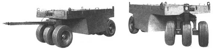
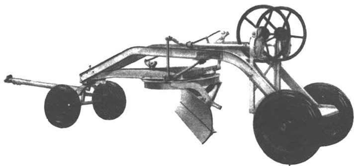