![]()
![]()
![]()
'Reconnaissance methods' are ways to get a first approximation of the amount of erosion in a given situation - this approximation may be all that is needed, or it could be followed by more precise studies if required.
The main advantage of reconnaissance methods is that, because they are cheap and simple, many measurements can be made and so the results can be reliable and representative - which means they are believable and usable - more so than a single precise measurement at a site which may not be representative.
Other advantages are that reconnaissance methods can usually be operated with semi-skilled staff; they may need little maintenance, for example erosion pins (discussed in the section Point measurements), and the time interval between measurements may be flexible, e.g. the pins can be measured after a month or after a season or year. Simple techniques may also be useful as demonstrations, when the object is not to measure the amount of runoff or soil loss, but to show farmers, or extension workers, or the general public, that a lot of erosion is taking place and something should be done about it. An example was the FAO project in Java from 1972 to 1976 where farmers who initially thought that erosion was negligible were entirely convinced by the visible lowering of the soil surface as demonstrated by erosion pins, and the amount of soil caught in simple catchpits as discussed in the section on Volumetric measurements (FAO 1976a).
A common problem in all off-station field trials is interference with the equipment by the local population. This can be plain curiosity of wanting to see what is inside a strange box; mischief-making like dropping pebbles down measuring tubes, or emptying rain gauges; theft of anything likely to be useful or saleable; or even mindless vandalism with no logical cause, although this seems to be less common in unsophisticated rural societies.
The solution in all these cases is not to let it happen and then react, but to anticipate it and avoid it. This means gaining the confidence and cooperation of the local community. They should already know about the project from having been involved in its planning - if they were not, the project is starting off on the wrong foot. But there is a large gap in understanding trials of a new variety, and understanding why measuring structures are being built in a streambed. So, a public relations programme is required to explain what is happening, how it will help and hence secure the support of the whole population.
A large hydrological study in Sri Lanka serves as an example of getting it right, but should not be taken as a model because there will always be special circumstances. In this case the population were largely literate so a simple one-page leaflet in the vernacular was widely distributed. Extension staff first visited and chatted to groups of village elders and then held meetings with all the village groups or associations in the catchment, including women extension officers to talk to the women's groups. Religion is important in Sri Lanka so all the temples and monasteries were also visited and wherever possible rain-gauges or stream-gauges were installed on temple grounds and the monks asked to keep the records. Schooling is also important, so the primary schools were all visited and groups of children taken out, with their teachers, into the field to be shown how rain-gauges and flow recorders worked, and runoff plots, and water-table tubes. The message throughout this campaign was simply "this is for your benefit - please help us to make it work."
One feature which worked in spite of the initial doubts of the local extension officers was setting up a "watchers club" among the school children. A main road and several tracks ran through the area and many of the gauging stations were at road bridges. Since it was not far from the capital there was quite a lot of non-local traffic. So each school was asked to 'watch over' any instrumented sites in their area. Members of the watchers club were given a simple button badge to wear as a token of the authority and support of the community for the project. Unfortunately it is hard to tell which of these activities had the most effect, but the result was well worth the effort for dozens of instrumented sites were operated for many years with negligible interference.
There are two approaches to estimating soil movement. One can estimate how much has been lost from a site, or estimate how much has accumulated at another site. The accuracy of these two approaches is usually very different. If the soil eroded from a field plot is collected in tanks and weighed, then even a coarse measurement of the weight gives a precise estimation of the soil loss. For example if the soil loss from a plot of 100 m� is measured to the nearest 0.1 kg, this corresponds to an estimate of soil loss to the nearest 10 kg/ha. By comparison, a direct measurement of the level of the soil surface is a very crude estimate. If the lowering of the soil surface were measured to the nearest millimetre, this corresponds with an estimate of the soil loss to the nearest 15 000 kg/ha, i.e. the precision is about 1500 times less.
However one should differentiate between precision and accuracy. Precision is the degree of refinement in measurement - so weighing soil caught in a catchpit to the nearest 0.1 kg is more precise than weighing to the nearest 1 kg - but it does not make the estimate more accurate - that is determined by the design of the experiment and the possible sources of error. Accuracy is not enhanced by quoting results with more precision than is justified. As an example, the depth of the soil loss can be measured to the nearest 1 mm and because it is a simple technique many measurements can be made. The calculated average figure would be more reliable, more believable, and probably more accurate from 100 measurements than from 10, but it is not any more precise. It is a common error to measure to one decimal place and then quote the average to two decimal places.
It can be tempting to collect information from local inhabitants, who are usually very willing to recount 'I remember' stories of where the gully used to be, or the floods of bygone years. But these should be treated with caution for there is no way of assessing their reliability or accuracy. Errors can creep in from several sources: inaccuracies of memory; distortion during translation; the tendency of people being interviewed to guess the answer which the interviewer expects or hopes for, then bend the evidence in that direction; the tendency to wishful thinking and "the past was better". Listening to the local village elders should be part of the job for all rural field workers, and can provide useful information, but it would be unwise to rely on it unless it can be verified.
The direct measurement of changes in soil level is appropriate in the case of localized erosion where rates are high and the position of the erosion can be predicted, such as steepland which has been deforested, or cattle tracks on rangeland. It is usually not suitable for soil losses from arable land because the surface level is affected by cultivation and settlement, although short-term changes have been studied in potato furrows in Australia (McFarlane, Delroy and van Vreeswyk 1991). Changes can be measured in one dimension for surface level at a point, or in two dimensions to give a profile or cross-section, or in three dimensions for volumetric measurements of rills or gullies.
Individual measurements of change in level at a single point will vary widely, but if it is an inexpensive and simple method, and a large number of points can be sampled, then a usable estimate can result.
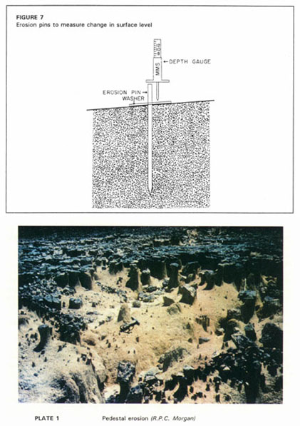
This widely-used method consists of driving a pin into the soil so that the top of the pin gives a datum from which changes in the soil surface level can be measured. Alternatively called pegs, spikes, stakes or rods, the pins can be of wood, iron or any material which will not rot or decay and is readily and cheaply available. Off-cut lengths of round iron bars for reinforced concrete can usually be picked up at little or no cost from construction sites. In some developing countries, iron or steel pins or nails might be stolen, in which case bamboo or reed canes cut locally might be more suitable (Figure 7).
The pin should be a length which can be pushed or driven into the soil to give a firm stable datum: 300 mm is typical, less for a shallow soil, more for a loose soil. A small diameter of about 5 mm is preferable, as thicker stakes could interfere with the surface flow and cause scour. A rectangular or square grid layout will give a random distribution of points with a spacing appropriate to the area being studied.
An illustration of the point method comes from a study in Japan, where pegs were installed to a 2 m square grid on three 100 m� plots with a 30� slope recently cleared of forest. Measurements of the peg heights were made every month for ten years and showed that the annual rate of erosion from each plot was almost consistent at about 13 mm/year (Takei, Kobaski and Fukushima 1981).
In another example the pin method unexpectedly gave a quantitative measure of the effect of a single heavy storm in western Colorado. As part of a long-term hydrology study in a 5 ha basin, pins were installed at 1.5 m intervals on six selected profile lines. All runoff and sediment from the basin is captured in a reservoir at the basin outlet, so that estimates of loss as measured by the pins could be compared with measurements of sediment from surveys of the reservoir. A heavy storm, with an estimated return period of 25 years, occurred shortly after the installation of the pins and the first reservoir survey, enabling an assessment of the isolated effect of the storm. The mean soil loss calculated from the pin results was a depth of 2.7 mm, compared with the estimate of the sediment held in the reservoir which would correspond to a loss of depth of 2.3 mm (Hadley and Lusby 1967), a good measure of agreement.
Some researchers slip a metal washer over the pin to give a better base from which to measure to the top of the pin. If there are likely to be cycles of erosion and deposition such as in a gully floor, the washer method may give useful additional information by falling to the lowest erosion level and being covered by any later deposition which can also be measured. On the other hand, the presence of the washer may cause turbulence and scour, or it could reduce splash erosion and leave the washer sitting on a pedestal of soil. All these variations and possible causes of false readings have been reported in the literature on the use of the pin method which is reviewed by Haigh (1977).
An indication of large changes in level, for example in a stream bed or gully floor, can be obtained by painting a collar just above soil level round rocks, boulders, tree roots, fence posts, or anything firm and stable. Erosion reveals an unpainted band below the paint line, indicating the depth of soil removed. When painting the collar it is advisable to mask the soil with old newspaper as paint accidently sprayed or brushed onto the soil might make it less erodible.
Another simple way to record the original level is to press bottle tops into the soil surface. The depth of subsequent erosion is shown by the height of the pedestals where the soil is protected by the bottle top. This leads to the use of naturally occurring indicators of changes in soil surface level.
When an easily eroded soil is protected from splash erosion by a stone or tree root, isolated pedestals capped by the resistant material are left standing up from the surrounding ground (Plate 1). The erosion of the surrounding soil is shown to be mainly by splash rather than by surface flow if there is little or no undercutting at the base of the pedestal. Like the bottle top method, it is possible to deduce approximately what depth of soil has been eroded by measuring the height of the pedestals.
In arid or semi-arid climates it is not unusual to find that the surface under trees is raised in a gently sloping dome. In a comprehensive project in Tanzania from 1968-1972 Rapp and colleagues suggested that the mounds are the result of the trees protecting the soil from splash erosion while the surrounding soil is eroded. By measuring the height of the mounds and the age of the trees from tree-ring counts, they estimated a soil lowering of about 10 mm/year (Rapp et al. 1972). However, based on later research in Botswana, Biot (1990) calculated that the rate of denudation as calculated by this method is ten to fifteen times greater than estimates by other methods. He offers the alternative suggestion that the tree mounds can be explained by a difference in bulk density between soils in the mounds and the surrounding flat soils. He concluded that the mound results from a raising of the local surface rather than erosion of the surrounding surface.
Exposed tree roots may offer a valid indication of change when the reason is obvious, such as erosion in a streambed below a paint collar, but exposed tree roots offered as evidence of sheetwash, or of wind erosion in dry climates, should be treated with caution for Biot's hypothesis may also apply. Very long-term rates of erosion (over several centuries) were estimated from tree root exposure in Colorado (Carrara and Carroll 1979).
Clumps of grass elevated above the surrounding soil surface should also be treated with caution for the change may be the result of the grass trapping soil particles splashed from the surrounding soil. This was conclusively shown in Zimbabwe where erosion was measured from runoff plots under various tobacco/grass rotations. After a few years the tufts of weeping lovegrass (Eragrostis curvula) were found to be several centimetres higher than the soil surface between, although the measured soil loss from the plot was negligible. Some simple tests with splash boards showed that there was no net soil loss from the plot, but consideration translocation of soil within the plot. Clearly it is necessary to be certain that changes in soil surface level are the result of erosion down rather than elevation upwards.
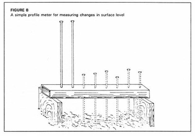
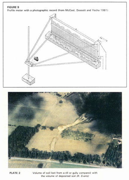
To measure small changes in surface level along a cross section such as an area with a number of parallel cattle tracks, a profile meter may be suitable. (The case of larger changes as in rills and gullies is discussed in the next section on volumetric measurements.) The requirement for a profile meter is to be able to set up a datum from which changes in level can be measured along a straight line and which can be re-established at the same points later to measure changes in level. Usually this takes the form of a horizontal bar with rods which can be lowered down to the soil surface, and is the same principle as used to measure surface roughness in studies of tillage and tilth. Such a device to measure surface levels accurately on grazing land was developed by Hudson (1964). Metal pegs were set unobtrusively at ground level in concrete blocks at intervals of 2 m. A light aluminium girder could be fitted onto any two adjacent pegs and this gave a firm datum from which the level to the soil surface could be accurately measured at positions marked on the girder. Between readings the girder was removed so that there was no interference with cattle movements. Measurements were taken to the nearest millimetre, which allowed annual changes to be clearly recognized. A similar device was used in the Philippines by Ramirez (1988) and is shown in Figure 8. Another approach was used by McCool, Dossett and Yecha (1981). In this case the pins are lowered to the soil surface at the same time and the profile is recorded by camera for later evaluation (Figure 9).
Several other more sophisticated profile meters have been developed and details are given in the section Further reading.
Estimates of soil loss based on three-dimensional measurements of volume can be used in different ways. For erosion from rills or roads, the length of the eroding section and changes in cross-sectional area are measured. For gully erosion, usually information is needed not only on the volume lost, but on how much the gully is increasing, so changes in length as the gully cuts back also have to be measured. The other volumetric approach is to measure or estimate the volume deposited as an outwash fan, or in a catchpit or reservoir.
Measuring the cross-section of all the rills in a sample area or along a sample transect is quick and easy, so the method is suitable for measuring change over short time periods, such as the change caused by a single heavy storm. The cross-section may be re-estimated from measurements of average width and depth if the shape is fairly uniform, or by summing the area of segments if the cross-section of the rill is irregular. (The arithmetic of cross-sections is discussed in the section Measuring streamflow.) The accuracy of estimates of total soil loss based only on measurements of rill erosion will depend on how much inter-rill erosion by splash and sheetwash is also occurring. Where inter-rill erosion is low, the underestimation from rill erosion alone may be from 10-30% (Zacher 1982).
A simple method for an immediate estimate of soil loss with minimum calculation dates back to 1937, when it was pioneered by A.N. Alutin of the United States Soil Conservation Service. A fixed-length transect is set out across the slope, and the cross-section area of each rill along the line is calculated from average width and average depth and summed. In the original units the transect was 13.7 feet, and the total cross-section of rills in square inches is numerically equal to the total soil loss in tons/acre (Hill and Kaiser 1965). The metric equivalent is a unit transect of 15 m, when the rill area in cm� is numerically equal to ten times the soil loss in tonnes/ha. Usually the results from a number of transects would be averaged. This assumes a soil bulk density of 1.5, and that the transects measured are typical of the area being studied.
Estimates of erosion from rill measurements have been compared with estimates of the volume deposited in outwash fans in England by Evans and Boardman (1994), who found that agreement was better when the measurements were made by experienced field workers. They suggest that estimates by measuring rills can be expected to be between twice and one half of the true value. The opportunity for a detailed assessment of the method occurred in 1985 when water from a burst water main cut a large gully through sandy soil drilled to a winter cereal. Nearly all the eroded soil was redeposited in the field (Plate 2) and estimated to be 304 m3. The soil eroded from the gully was measured as 320 m3, the discrepancy probably the result of fine particles being carried away in the runoff.
A further simplification of estimating soil loss from rills was tried out by Watson and Evans (1991) who compared direct measurements of rills in the field with estimates made from a study of colour slides taken in the field. They concluded that "It is possible for an experienced observer to make reasonably accurate decisions about volumes of soil eroded by looking at photographs of fields taken on the ground". On eight of the eleven fields measured in the study, the ratio between estimates from field measurements and estimates from the photographs was between 0.81 and 1.11, with extreme values of 0.67 and 2.12. The discrepancies were thought to arise mainly from the difficulty of estimating the length of rills on the photographs because of foreshortening. They conclude that there is room for improvement in the technique, but that it does offer a quick and simple method of estimating field soil loss where rill erosion is the dominant process.
Clearly figures in tonnes/ha from these methods must not be treated as if they were reliable accurate measurements, but they may be useful in providing a quick simple comparison of the effect of alternative cropping or cultivation practices.
When the progress of gully erosion is being studied, measurements are needed both of the horizontal spread of the gully and vertical changes within the gully.
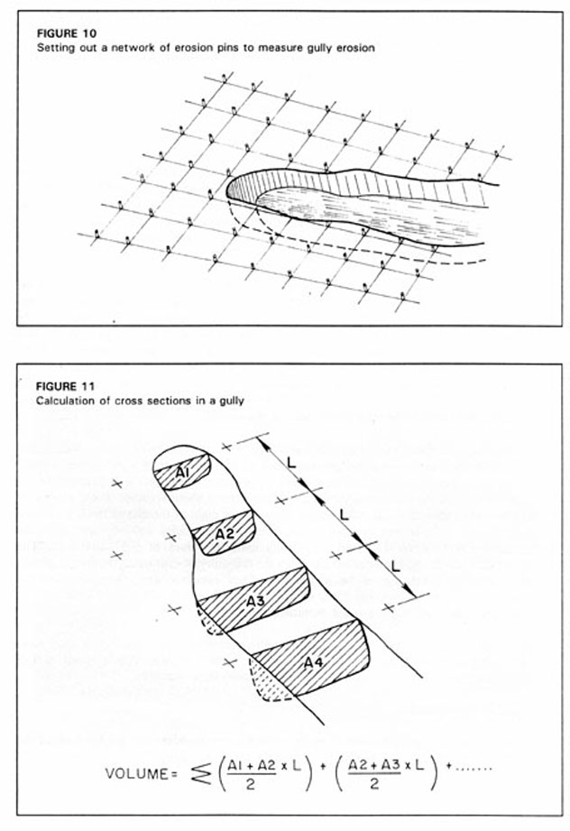
To measure the surface area, and changes from cutting back or bank collapse, a rectangular grid of erosion pins is set out at an appropriate grid interval of perhaps 2 or 5 m as in Figure 10. From measurements along the grid lines from the nearest pin to the gully edge, the surface area can be plotted on squared paper. The grid lines also serve as the transects for cross-sections across the gully. A string is stretched at ground level along a grid line with markers at fixed intervals of, say, 1 m. At each marker the depth is measured from the gully floor using a survey staff or a ranging rod, and the section can be plotted. The volume of soil lost from the gully is calculated as in Figure 11, and subsequent measurements will quantify the changes.
The bed of a gully may at any one point have cycles of cutting down at some times and deposition at others, for example when a large bank collapse puts a large quantity of soil into the flow. The use of erosion pins with washers may provide information on such changes of level, as described in the section Measuring change of surface level.
Another method of assessing the cutting back of streambeds or gully sides is to drive in horizontal small-diameter metal rods. An increase in the length of rod exposed shows how much the bank has retreated, and the measurement can be simplified by spray painting collars round the exposed rods. However this technique should not be used if placing the rods will affect the soil's resistance to erosion. In gravel soils, driving the rods can loosen, and increase their erodibility, or in alluvial soils with low tensile strength, the rods can act as a tension reinforcement and reduce slumping, toppling, or cantilever failure (Thorne 1981).
Changes in a gully may be interpreted from the use of sequences of photographs. The position of the camera and the direction of the photograph must be carefully recorded. It is surprising how seldom 'before and after' photographs of gullies are lined up accurately. For studies of the long-term development of gullies, aerial photography can be a useful tool. An interesting example from Zimbabwe allowed the correlation of the changes in a gully with the changes in land use and vegetation in its catchment over a period of forty years (Keech 1992).
Surveys of sediment in reservoirs can be used to make quantitative estimates of erosion as discussed in chapter 5, but simple catchpits may be used to demonstrate comparisons (Plate 3). It is not possible to get a reliable estimate of the total soil movement unless the receiving reservoir is large enough to contain the whole flow and sediment load, but smaller pits which only catch an unknown proportion of the sediment can still be used to obtain comparative information. This was done successfully in the FAO project in Java previously referred to in connection with erosion pins (FAO 1976a) where small catchpits were dug on two small parallel catchments, one of which was terraced and the other not. Previously skeptical farmers were convinced of the effectiveness of terracing when they saw that there was much less soil in the catchpit below the terraced plot than the untreated plot.
Another example is the Japanese study previously referred to (Takei, Kobaski and Fukushima 1981). Two small plots were set up side by side with a simple catchpit below, with one plot left bare and the other reforested. Again a clear difference between the amount of sediment accumulated demonstrated the effect of reforestation, although the actual amounts of soil caught in the pits could not lead to quantitative estimates of the amounts of erosion.
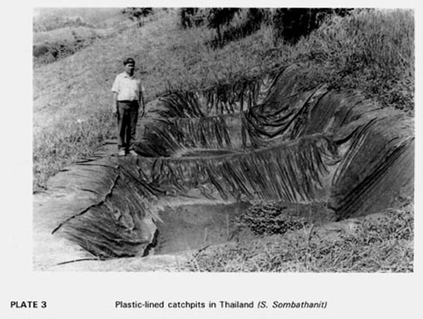
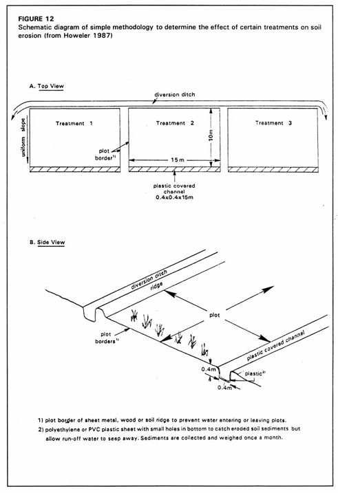
In Colombia, on-farm demonstration trials initiated by the International Centre for Tropical Agriculture (CIAT) used plastic-lined channels to compare the soil movement under different cassava-based cropping systems (Howeler 1987) (Figure 12). More recently a farmer-operated trial in Thailand with catchpits lined with polythene sheets demonstrated a huge difference is soil loss from a plot under hill rice with no conservation measures, and a plot with grass strips and strip cropping (Sombatpanit et al. 1992) (Plate 3).
A simple method for measuring relative soil movement at different points in the catchment uses 'mesh bags'. A 30 cm by 30 cm square of 5 mm mesh nylon fabric is fastened on 3 sides over the same size of 2 mm mesh. The bags are pinned to the soil surface with the open edge uphill in a line across the contour to measure horizontal variation, or up-and-down slope to measure variation down the catena. Some of the soil moved by surface flow is trapped in the mesh bag and may be dried and weighed at intervals. The method is an inexpensive and simple way of studying relative soil movement at different points in the field (Hsieh 1992).
As an alternative to excavating catchpits, gully checkdams can be used to give an approximation of the effect of different treatments in their catchments.
Geomorphological processes tend to require careful and long-term study rather than reconnaissance estimates and so are out of the remit of this Bulletin. Readers wishing to consider this topic are directed to the section Further reading relating to this chapter.
![]()
![]()
![]()