![]()
![]()
![]()
Environmentally sound forest road construction techniques as holistic, interdisciplinary approaches that take into account the need for landscape and wildlife considerations should replace purely technology-oriented solutions (Litzka and Haslehner, 1995) and are to be guided by the following principal considerations:
· any disturbance to the landscape is to be kept to the absolute minimum;
· environmentally sound correction of poorly located and designed roads at a later stage is virtually impossible;
· reckless and incompetent construction work may destroy the beneficial effects of even the most carefully selected road location;
· undesired effects and scars inflicted on the landscape can seldom be remedied at a later stage and only at much higher costs.
Equal attention is to be paid to the three phases in road construction projects (Litzka and Haslehner, 1995), namely, planning and design, construction operation, and integration which comprises bioengineering as well as landscaping measures. All operations undertaken are guided by the consideration that unless the forest is left in a condition that will permit the attainment of a desired future condition, sustainability cannot be assured (Dykstra and Heinrich, 1996).
The detailed information given in the following chapters focus on construction activities. Some details also refer to integration measures as they are accomplished by means of excavator.
Prior to clearing of the construction area, the design information is to be moved from the plan to the ground by staking. There are a variety of staking methods which can be employed, however, for the mechanized construction of forest roads in the mountainous terrain of Austria, where the gradient rather than the horizontal alignment is the controlling factor, simpler methods of location have been developed (Sedlak, 1985).
At the study sites the gradeline method was employed, referred to as "zero-line method" in Austria, which has proved to be the ideal tool for fitting the road to the natural terrain as closely as possible. It can be described as a step-by-step method for fixing the location line with a given longitudinal gradient directly in the terrain (Litzka and Haslehner, 1995) by means of a hand-held clinometer. The gradeline itself represents the intersection between subgrade of the road and the slope, and serves as the guideline for mechanized road construction (Sedlak, 1985).
In using this simple method there are no real limits to project accuracy (Litzka and Haslehner, 1995) as exact costing of earthworks is not necessary due to the high performance of the construction equipment employed. Such simple methods must not be confused with inadequate planning as skill and experience are required to find the most feasible road alignment, both from the environmental and economic point of view (Sedlak, 1985).
Figure 3. Road template
Once the gradeline is staked, clearing of the construction area by felling the trees within the clearing limits (see Figure 3) should be carried out. In difficult terrain the clearing limits are marked by tying coloured plastic tapes to trees or branches.
The felling itself, as the landowners responsibility, has to take account of the anticipated method of extraction by the excavator operator with regard to felling direction and harvesting method to be used. A modified full-length method is normally applied as it facilitates log removal from the construction area by excavator most efficiently. This method requires that trees are delimbed and topped at the felling site, except where the trees are too large to be handled by the excavator, when some cross cutting will be necessary.
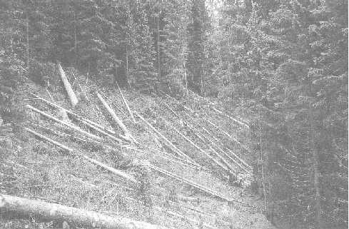
Photo 6. Modified full-length method should preferably be used in felling at construction site
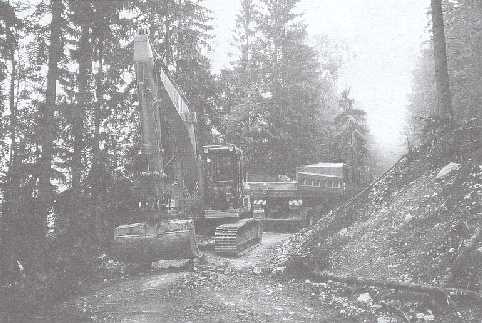
The introduction of hydraulic excavators in forest road construction has been the major step towards environmentally sound road construction practices. In hilly terrain in Austria the use of excavators not only replaced bulldozers in forest road construction but also improved the quality of roads while reducing environmental impacts of these complex engineering structures, whereas in steep terrain their use is the only option to make road construction even feasible.
Road construction technique by hydraulic excavator comprises the following five distinct phases stated below:
i) log removal from construction area
ii) topsoil removal from construction area
iii) excavating base for fill foundation
iv) fill slope construction
v) subgrade and cut shaping
This order is not necessarily followed in the actual construction sequence on the construction site. Some operators will arrange single activities in sequence, whereas others will chop and change between tasks. The latter are at risk burying organic materials in the fill and failing to separate excavated local materials taking account of their anticipated use in building up the fill in layers.
However, even if a well-trained and experienced professional operator follows his personal optimum sequence of construction activities, log removal from the construction area will always be the first phase in road construction and close supervision has to ensure best construction practices to be followed and compliance with the project plan approved by the authorities. The road gradient should frequently be checked to ensure that the gradeline is followed since stakes marking the gradeline will be obliterated during topsoil removal.
Figure 4. Road construction technique by excavator
Close supervision is important when road construction works are carried out by contractors who are paid per running metre of road completed rather than on an hourly rate. Past experience has shown that contractors paid by the running metre tend to decrease their own costs by poor construction practices (see also Chapter 5.1.1) where proper establishment of the fill foundation is often neglected. Road failures and even landslides triggered by construction flaws have been the consequence, in particular due to the inadequate fill foundation provided by the excavator in the third phase.
On slopes where substantial rock blasting is specified the topsoil removal from the construction area will be followed by rock drilling and blasting to facilitate a solid foundation.
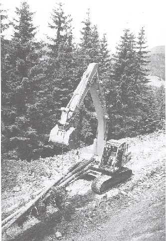
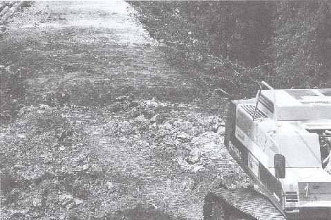
Photo 7. Log removal by means of chain attached to the bucket's hook
i) Log removal from construction area
Once the trees have been felled within the clearing limits, road construction activities will start by log removal from the construction area. As already mentioned in Chapter 3.1, trees should preferably remain in full length in order to minimize the delays to the work of the excavator and ensure maximum performance.
After several trees have been attached by means of chain to the excavator's bucket or sometimes just by balancing stems put on the bucket, the excavator pulls or carries logs out of the construction area by moving backwards to roadside storage. Logs should be stored at roadside in several places rather than transported over long distances to landings due to the low driving speed of excavators. Such frequent storage will reduce extraction cost and facilitate any further processing.
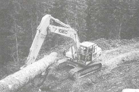
Photo 8. Log removal at the construction site by means of the excavator's bucket
ii) Topsoil removal from construction area
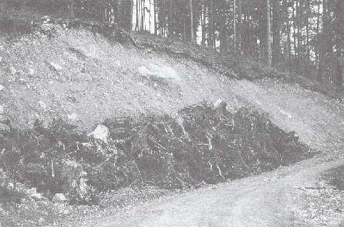
The log removal phase will be followed by clearing the construction area from wood residues and organic topsoil. Bigger branches are piled up by pulling them with the bucket's shanks to be removed later and to be spread out on the fill slope. Deposition of branches on the fill slope helps to keep exposure of unprotected surfaces as short as possible, provides immediate erosion control from fill slope and facilitates an earlier natural or man-made revegetation.
Stumps, tree tops and other vegetative debris are removed by the excavator's bucket from the construction area in front of the excavator and placed by the operator with accuracy and care along the base of the fill slope in order to form a filter windrow. The additional width between the construction limit and forest edge ensures that space is available to deposit debris outside the construction area and prevent organic material being mixed into the base of the fill.
In contrast to stump removal by bulldozers, where it is recommended to leave stumps 0.8 to 1.2 m high to provide added leverage (FAO, 1989), there is no need to do so in using excavators as stumps are being dug out. This ensures the highest wood recovery rate and therefore contributes to the economic feasibility of a road project.
The established filter windrow will drastically reduce damage to forest stands alongside the road by excavated materials, namely stones, escaping downhill and also prevents sediment from entering into stream channels.
After stump removal has taken place, the organic topsoil will be stripped and material unsuitable to be used in the fill will be removed from the construction area and placed in the additional width between the construction limit and the forest edge above the already established filter windrow. If working in grassland or where grass covers the forest floor the operator should be advised to separate and to lift turfs carefully as they can be used to establish vegetation on the fills rather quickly.
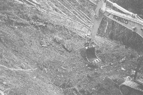
Photo 9. Wood residues and organic top soil will removed in front of the machine and spread on the rear fill slope
iii) Excavating base for fill foundation
At the toe of the anticipated fill slope a base, about 1 m wide and 0.5-1.5 m high, is excavated to establish the foundation for the fill on solid ground. The steeper the slope the deeper under subgrade level the base will be established limited by the excavator's maximum digging depth. Excavated materials should be separated by the operator taking account of their anticipated use in building up the fill.
Earth will then be deposited parallel to the toe of the fill slope, immediately above the established filter windrow to provide the downhill raised borderline of the foundation base and forming the lower part of the fill widening (see Figure 3). Excavated mineral soil suitable for use in fill construction is temporarily heaped uphill on the construction area next to the excavator. Big boulders suitable for retaining structures are piled separately, either alongside the road or next to planned culverts.
In steep terrain where slopes with rock formation near or above ground level are to be crossed, the base for the fill foundation should be provided by breaking out rock either by rock hammering or rock blasting.
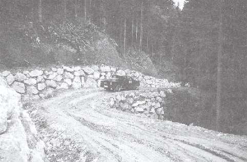
Upon this solid base, boulders are placed by the excavator with accuracy and care, as well as compacted by means of the excavator's bucket in order to build up a solid foundation for the fill. The establishment of a fill foundation reduces the length of fill slopes considerably and makes road construction in steep terrain feasible. This feature is of great importance when side slopes exceed 40 percent as balanced road sections can be achieved with considerably less excavation (FAO, 1989).
In contrast, applying traditional side cast techniques by bulldozer the length of the fill slope would amount to about 3.5 m, 12 m and 22 m for slope gradients of 45 %, 60 % and 70 %, assuming an angle of repose for side cast material of about 37º, and on slopes of over 75 % a fill cannot be established at all (Gorton, 1985). It is suggested that a balanced road design provided by excavator construction results in approximately 25 to 35 percent less excavated material compared to the traditional side cast technique by bulldozer where most of the road width is cut into the stable hill side (FAO, 1989).
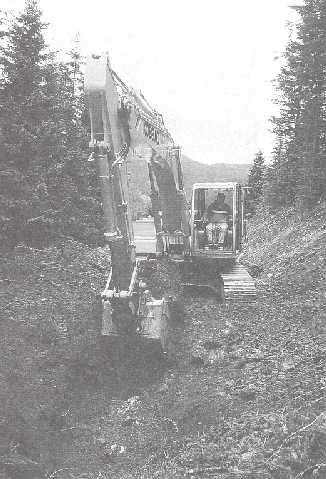
Photo 10. Excavating a solid base for the fill foundation
iv) Fill construction
The main feature of road construction technique by hydraulic excavator is balanced road sections where cut excavation is incorporated into the layered fill. Suitable coarse material is placed against the fill foundation to establish the base fill layer. In general, the fill needs to be built up in well compacted layers to develop strength since it must support traffic. The excavated materials are spread by the excavator's bucket to form a 30 to 50 cm layer which is to be compacted by several excavator passes before being covered by the next layer of less coarse material.
The obvious advantage of balanced road design is that loose, unconsolidated wasted material is minimised compared to traditional road construction techniques by bulldozer. To build up the fill foundation and the fill itself, requires highly skilled and experienced operators, since fill failures, due to improper construction techniques, may not only destroy parts of the roads but may also trigger landslides in steep terrain making large areas unproductive and inflicting scars on the landscape.
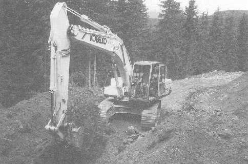
Photo 11. Fill construction is one of the most responsible duties in proper road construction - one can see the separated materials piled hillside
Only mineral soil, free of organic debris such as stumps, tree tops and humus should be used in fill construction as organic material will decompose and result in uneven settlement and increase the potential for failure. Excess material will, depending on its size, either be incorporated in the road subgrade of already established road sections or temporarily laid aside for use in the next work cycle. If excess material cannot be used, it can be removed with a dump truck.
v) Subgrade and cut shaping
The last exercise to be accomplished using the hydraulic excavator will be finishing the subgrade, establishment of the hillside ditch and final shaping of the cut slope.
Smaller holes in the uppermost fill layer will be filled up while the layer gets continuously compacted through excavator passes in order to achieve a firm subgrade. Finally smoothing and compacting of the subgrade surface by means of the excavator's bucket will provide the coarse subgrade.

Photo 12. Smoothing and compacting the coarse subgrade by means of the excavator's bucket
Depending on the parent material at the construction site and the availability of material suitable for gravelling, a sealing layer of gravel or similar material should be applied to the coarse subgrade (Photo 13), compacted and finally shaped and smoothed in order to provide a crowned road (Photo 15) or sloped roads if specified by the supervising forest engineer. All of these activities can be carried out by the excavator.
While the final finishing work is being done to the road surface, the hillside ditch can be formed. This allows for immediate draining of the road structure preventing damage to road structure and erosion from exposed surfaces during the construction phase as favourable weather conditions for road construction work often rapidly deteriorate in mountainous regions of Austria and heavy thunderstorms force to close road construction work.
As excavating the ditch interferes with the cut, final shaping of the cut slope to provide the desired slope gradient will depend on completion of coarse subgrade and ditch. The edge at the top of the cut is to be rounded in order to avoid overhanging floor vegetation and the cut slope to be smoothed in by the excavator's bucket in order to prevent downhill drifting of loose cut slope material after completion of the road (Photo 14). Material eroded and escaped into the ditch not only increases maintenance costs as it has to be removed, but also obstructs water drainage.
After the road construction work by excavator has been finished, the forest road is left in a condition that will allow hauling trucks and off-road vehicles to pass (Photo 15). Although immediate access is provided, hauling should be restricted to trees harvested during road construction in order to avoid deterioration in timber quality. Otherwise, roads which have usually been constructed during the summer season, should be allowed to go through an entire winter and the subsequent melt-season before permitting their use by heavy machinery.
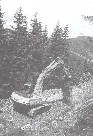
Photo 13. Suitable local material will be spread on the coarse subgrade by the excavator to provide a sealing layer
During the following construction season the road will finally surfaced. Settlement will be corrected and gravel will be applied to the running surface. The final smoothing and shaping of the road surface will either be accomplished by means of a grader or occasionally by excavator equipped with a slope finishing bucket. Following up the grader is a vibration roller providing a smoothed, compacted surface to ensure an effective drainage from the road surface (for details see Chapter 3.6).
Where rock surfaces are to be crossed, final shaping of the cut slope and establishment of the ditch will be provided by means of hydraulic hammer attached to the excavator. In such road sections the longitudinal water drainage facility can best be described as a deepened road edge rather than as a real ditch where on the roadside part can be driven upon so that road width and rock disintegration can be kept to the absolute minimum.
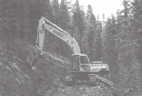
Photo 14. Final shaping of the cutslope by means of the excavator's bucket
Photo 15. A sealing layer of gravel or similar material will be applied on the coarse subgrade and finally shaped to provide a crowned road
The steeper the slopes the more rock disintegration will be involved in road construction activities since rock outcrops cannot be bypassed or rock surfaces avoided. The excavator production rate approaches the bulldozer production rate as side slope increases due to the fact that the excavator's bucket is much more effective at ripping than the dozer blade (FAO, 1989). The excavator production rate may even be higher on slopes steeper than 60 % as indicated by performance studies carried out under similar terrain conditions (Gorton, 1985).
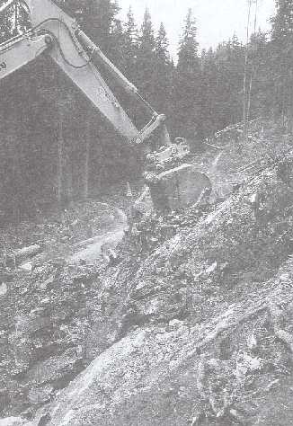
Photo 16. As long as rock can be ripped, the excavator solely equipped with a suitable type of bucket will be employed in rock disintegration
Whether or not a rock can be ripped, rock excavation can be accomplished by means of excavator solely equipped with the a suitable type of bucket or other excavator attachments like hydraulic hammers or hydraulic drilling units. Pneumatic equipment is now widely replaced by hydraulic equipment which is not only quieter than pneumatic hammers, but also operates at lower cost as the excavator's hydraulic pumps do the work and an air compressor is not needed.
However, as long as the rock can be ripped, the excavator equipped with a suitable type of bucket can be employed. Since ripability of rock depends on the type of rock and on the degree of fracturing and/or weathering, the experienced planning engineer will arrange equipment needed in rock disintegration to be available at times which minimise down time for the excavator.
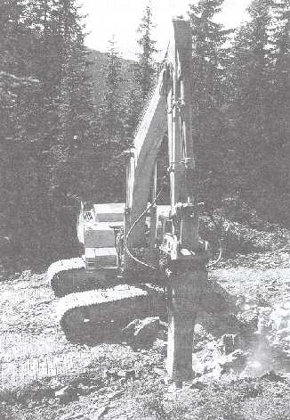
Photo 17. The use of hydraulic hammer close the gap in rock disintegration by rock buckets on the one hand and by blasting on the other hand
The use of hydraulic hammers attached to excavators is considered the ideal solution for rock disintegration in order to avoid rock blasting where the parent rock is no longer rippable by the excavator's bucket but still has enough planes of weakness for economical operation with hydraulic hammer. Although tremendous progress has been made in drilling and blasting techniques in the past, rock disintegration by hydraulic hammer meets the demand in reducing environmental impacts.
Since a hammer need not to be a full time attachment and coupler systems provided by manufacturers ensure that there is no loss of bucket breakout force by their use, the bucket can be taken off and replaced by a hammer within a few minutes. Hydraulic hammers therefore make an excavator even more versatile and cost effective as drilling equipment and explosives are not needed to break out pockets of rocks and alterations in road location can be avoided.
The main features of hydraulic hammers and advantages inherent to their use can be described as follows:
· rock hammers are enlarging the application range of excavators;
· less non-work time of the excavator operator as interference of blasting operation does not occur;
· desired cut slope gradient and shaping can easily be performed by the skilled excavator operator;
· size of disintegrated rock material can be controlled by a skilled and experienced operator in order to facilitate incorporation of rock material;
· accurate construction of hillside ditch for water drainage;
· less excess material to be removed through accurate rock disintegration;
· the hydraulic hammer is the only equipment needed in addition to the excavator already employed at construction site;
· blasting danger can be avoided.
In difficult terrain the decision on road location is based on the principles of best road construction practice, limitations due to forest ownership, and on terrain constraints. Therefore rock surfaces cannot always be avoided and substantial rock blasting may be specified by the planning engineer.
Although more sophisticated blasting techniques have been developed, rock blasting is best avoided as the use of rock drilling equipment and explosives increases road construction costs and there are substantial risks in using explosives. However, if blasting is specified, sophisticated drilling equipment attached to the hydraulic excavator, which facilitate vertical as well as horizontal drilling, should be used (for details see Chapter 4).
Since there is no real limit to the drilling position, the blasting technique can be adjusted to rock condition and the use of an excavator as carrier vehicle ensures that the road width can be kept to the absolute minimum as excavators do not require additional road width for manoeuvre.
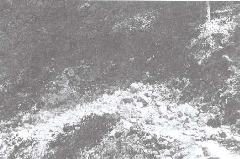
Photo 18. Sophisticated hydraulic drilling units for excavators enable vertical as well as horizontal rock drilling
The blasting technique used at study site 3 where the road had to be cut into stratified layers of compact limestone, can be described as follows:
· use of several vertical drilling holes instead of one long horizontal drilling hole as used in dolomite rock for example;
· vertical holes were placed in a rectangular pattern 1.5 m square;
· hole length ranged from 3 to 4 m depending on the distance between rock surface and planned subgrade;
· amount of explosives loaded per drilling hole varied according to the hole length and ranged from 1.5 to 1.75 kg;
· use of sophisticated primers which facilitate loads to be exploded with delay in millisecond range;
· loads separated by the holes connected so that the explosion is caused by the same ignition.
This blasting technique using minor loads separated in several drilling holes with less disruptive effect on the bedrock can be described as "soft" blasting. On the one hand, it only loosens the rock to be removed by excavating but avoids disturbing the stratified bedrock as well as other blast-related damage. On the other hand, due to its less destructive effect, the size of rock material can be controlled which is important for subsequent use of disintegrated rock material in the road structure.
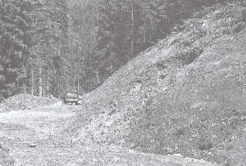
Photo 19. Proper blasting technique provides material suitable in size to be incorporated into the road structure while avoiding damage to the forest stands alongside road
The use of primers with delays allows the direction of movement of rock material caused by the explosion to be controlled. In general, the primers will be set in the holes following the staked road course so that the explosives loaded in the front holes will go off first and blasted rock material will be directed by the subsequent exploding loads towards the already established road section.
In road sections where substantial rock blasting is needed, full bench construction of road with longitudinal transport of excess material is usually specified and rock blasting along the base of the fill will be required in order to establish the base for proper fill foundation.
Damage to adjacent stands at construction site by material escaping downhill during the explosion can be reduced significantly due to the "soft" character of this blasting technique. Its use is also highly recommended in the vicinity of springs as they might be affected by the disruptive effect on stratified bedrock of less sophisticated blasting. If buildings or infrastructure are at risk even by applying soft blasting techniques, hydraulic hammers are the only solution but their use has to be restricted to short road sections for cost reasons.
One main advantage of road construction by hydraulic excavator, among others, is that balanced road construction with excavated material incorporated into the road structure can still be carried out on steep slopes whereas in road construction by bulldozers full bench construction technique with end hauling of excess material would have to be applied.
However, where rock surfaces are to be crossed and the base for fill foundation cannot be provided by the excavator, full bench road construction is unavoidable. The longitudinal mass transport will then either be provided by means of the excavator or by dump trucks depending on the amount of excess material to be removed.
In contrast to the statement that operating distance for materials movement by excavator is limited to its swing distance (FAO, 1989), longitudinal mass transport with distances of up to 70 metres was found at the study sites. Long distances for mass movement by excavator cannot be recommended in general, but are acceptable in road projects with only few short road sections where mass movement is needed and therefore the costly use of a dump truck can be avoided.
Another advantage of longitudinal mass transport by excavator is that the moved material will be incorporated in the road structure of already established road sections rather than wasted. Consequently, there is no need to find stable disposal areas which have to be integrated into the landscape. Furthermore, the incorporated and compacted material is unavailable for erosion. The experienced supervising engineer will decide whether excavator or dump truck should be employed.
The most effective way to prevent watershed disturbance and increased soil erosion rates is to minimise the total length of roads. It has to be kept in mind that even the best developed drainage system established during the road construction process will only reduce rather than avoid impacts on natural watersheds.
Nevertheless, forest roads are essential for industrial timber extraction, for providing convenient access to the forest for applying sustainable forest management practices and for monitoring purposes while often benefiting local communities at the same time (see also Chapter 2).
Some of the most common drainage-related problems are:
· inadequately sized stream crossings, in particular culverts;
· inadequate road surface drainage;
· poor drainage of skid trails joining roads;
· lack of road maintenance after logging operations, hauling activities or erosion caused by thunderstorms so that ditches and culverts do not work.
Photo 20. Water drainage is to be ensured from the start - intermittent springs often appear after heavy thunderstorms and transfer water from planes in the bedrock onto the newly established cut slope and might trigger slides
Photo 21. Slope material escaped into the ditch requires immediate action to avoid obstruction of water drainage and to prevent costly repair work of slips
Following environmentally sound construction practices, the measures stated below are considered obligatory to provide satisfactory water drainage and consequently to prevent erosion:
· the road fitted as closely as possible to the terrain and to be restricted in width to the absolute minimum for safety and anticipated use;
· soil disturbance and surfaces exposed to erosion are to be minimized by balance of cuts and fills;
· road gradients should be varied to reduce concentrated flow on road surfaces, in ditches, in culverts and on fill slopes;
· gravel should be applied on the running surface not only for more convenient use by vehicles but also to provide a more weather resistant sealing surface;
· surface water from joining skid trails should be prevented from flowing on to the road and becoming man-made streams with the potential for erosion as they flow downstream;
· ditch gradients should be adjusted to the specific soil condition at the construction site to keep collected waters moving to culverts and preventing sediment deposition and ditch erosion;
· road drainage features are to be designed and spaced so that peak drainage flow from surfaces will not exceed the capacity of the individual drainage facilities;
· culvert location are to be spaced not only at certain distances but are to be installed where actually needed when crossing streams either perennial or intermittent, and in ephemeral areas;
· prefabricated steel culverts pipes are to be installed in preference to articulated concrete pipes as the latter are at risk of collapse under the load of heavy hauling during periods of weakened road strength and consequently to obstruct or to block water drainage;
· culverts are to be protected from plugging by using sediment catch basins and debris racks where needed and water is to be prevented from eroding and undercutting the culvert by rock armoured inlets;
· outlets of culverts are to be armoured with rock boulders to prevent emerging water from eroding the fill slope where water will not be released onto a stable area;
· fords should be considered as alternative to culverts in crossing perennial streams carrying high loads of sediments or the combined use of culvert and ford, in particular where torrents are to be crossed, with a culvert for the normal run-off and a ford for high floods;
· individual drainage facilities are to be inspected periodically for need of maintenance and following after heavy thunderstorms and after logging and hauling activities in order to start immediately repair work if needed;
· damage to road features should be avoided by effective road-use management which includes access control in general as well as road closure during wet seasons.
One significant feature in road construction by excavator is the fact that drainage facilities and erosion control features will either be provided in each single work cycle of the ongoing road construction process or can easily be established by means of excavators at any time required without need for additional machinery. In general, culverts will be installed when the road cross section is established either for the entire road or for those parts finished during the construction season.
In general, minimum gradients of 2-3 % and maximum gradients of 9-12 %, in exceptional cases up to 16 % are considered appropriate for forest roads (Sedlak, 1996). Nevertheless, other maximum road gradients might be specified by the authorities according to specific site conditions of individual road projects. Gradients for the road crown will range from 2 to 5 % and from 3 to 6 % for insloped roads (Winkler, 1992) to ensure an effective drainage from the road surface.
Ditch gradients should range from 2 to 8 % (Almas et al., 1993), just steep enough to keep collected waters moving without carrying excessive sediments. Gradients steeper than 8 % might result in too much momentum of collected water and the carrying of sediment and debris for long distances, whereas gradients which are too shallow lead to silting up of ditches. Culverts should be maintained in order to avoid failure due to plugging by debris and sediment.
As one can see from the specifications made by the authorities (Table 6) for the individual road projects, fords are often specified in crossing perennial streams. This reflects the environmentalists' general preference of fords against culverts (Sedlak, 1996) as the latter are considered to interfere with the stream ecosystem.
Once the road subgrade has been constructed and culverts have been established, the road is allowed to go through an entire winter and the subsequent melt season, before surfacing takes place during the construction season in the following year.
Settlement in the road subgrade are filled with coarse gravel and well-graded gravel is applied to the running surface. Only the use of well-graded material, where smaller particles tend to fill the empty spaces between the larger particles during compacting performed by rollers, will ensure that a smooth sealing surface can be achieved.
Once the gravel has been applied on the running surface the final shaping and smoothing will usually be provided by means of a grader. Depending on the material applied the final shaping will occasionally be done by an excavator equipped with a slope finishing bucket as at study site 3 where limestone material from local quarries was used for surfacing.
Finally, following up the grader is a vibration roller for proper compaction. Compaction is the process of increasing the density and the strength of the soil. The effectiveness of the compacting process will be affected by gradation of gravel material applied, its moisture content and the compactive effort. Proper compaction of fill material is not only the key to a stable, balanced road design (FAO, 1989) but also results in a significant reduction of maintenance cost and helps to prevent washing away of very loose silts and fine gravels when there is heavy rain.
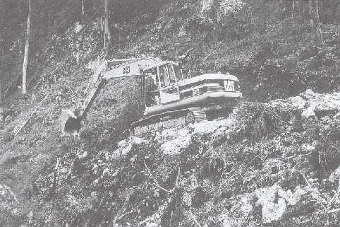
Photo 22. Shaping of the gravel material applied on the running surface will occasionally be carried out by an excavator solely equipped with a slope finishing bucket
The costs of using well graded material for the road pavement can be substantial (Almas et al., 1993) and could cost as much as 70 % of the total cost of the road on weak clay subgrades (Sedlak, 1996). The use of substitute poorly graded material is not recommended. The initial financial savings are soon overtaken by the higher maintenance costs.
Options for saving on the costs of gravel material are given below (Sedlak, 1996)
· road construction during frost periods to prevent subgrade deformation and the need to fill up settlements with costly gravel;
· recycling or processing local material wherever feasible;
· use of polypropylene fabric layers between subgrade and gravel layers to prevent clay intrusions;
· subgrade stabilization using lime or other suitable substances as recommended in the road engineering literature.
At the study sites the costs of surfacing which cover the cost for gravel material itself and its transport, for grader as well as roller operations, ranged from about 4 to 47 percent of the overall road costs (see Chapter 5.3) at the three construction sites and are less than the costs mentioned above due to the availability of suitable gravel material from local quarries.
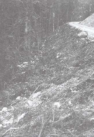
Photo 23. Topsoil removal will be spread on the rear fill slope in each work cycle
Some of the measures which are usually undertaken to stabilise slopes and to prevent erosion from exposed surfaces, will already be performed in each single work cycle as they are inherent features of proper road construction technique by excavator. In particular these measures are the following:
· a fill slope cover which provides immediate erosion control will be continuously performed during the phase of topsoil removal from the construction area in each single work cycle of the road construction process;
· finally shaped, smoothed and compacted cuts performed in each single work cycle ensure that loose material is removed from slope surfaces which would otherwise be exposed to erosion;
· inlet and outlet protection structures of culverts as well as retaining walls for slope stabilization will be built up by the excavator using the boulders which have been separated from other excavated materials during construction operations;
· the fill slope will be revegetated by turfs where a grass layer covered the soil at construction site.
Photo 24. Erosion control of fill slope by debris cover provided immediately after fill construction
Beside the measures already performed by applying the excavator construction technique, vegetative treatment of slopes for early revegetation and prevention of erosion has become a standard procedure in Austria (Sedlak, 1996). Out of the wide spectrum of bioengineering measures which range from simple seeding procedures, mulching etc. to combined use of retaining structures and living plants, the most inexpensive way of grass seeding either by hand or by hydro-seeding technique has been approved by the authorities for all 3 road projects.
Employing bioengineering methods not only prevent erosion but also ensure a better blending into the landscape and sometimes perform an additional benefit due to the draining effect of structures incorporating living plants. These bioengineering methods are generally preferable to purely technology-oriented methods such as concrete supporting walls (Litzka and Haslehner, 1995).
Photo 25. Immediate erosion control of cut slope by stumps which had been removed during the phase of topsoil removal from the construction area
Photo 26. Retaining walls built up from boulders by means of excavator are quite costly but cannot always be avoided in crossing wet and unstable areas due to terrain constraints in road location in mountainous regions
![]()
![]()
![]()
![]()