![]()
![]()
![]()
S. F. POTTS
Formerly Entomologist, U.S. Forest Service, U.S. Department of AgricultureThe application of pesticidal dusts, dilute sprays, concentrated sprays and aerosols, for the control of pest and diseases in agriculture and forestry, has become widespread. The method has not approached its potential of use and many areas could be treated more efficiently and effectively, and at a lower cost, if better data and information were readily available. This paper, to be concluded in the next issue of Unasylva, describes present practices in North America and, besides dealing with insecticides and fungicides, includes information on equipment and methods for applying the new herbicides, silvicides, foliage nutrients and fertilizers. The possible harmful effects of the extended use of chemical control methods in agriculture and forestry are of much concern to FAO and many other agencies. These effects are being studied but much more data needs to be collected.
Recent developments in the application of insecticides in the form of smokes, liquefied-gas aerosols, and finely atomized sprays, with equipment operated from the ground and from aircraft, have attracted attention to the significance of particle or droplet size as a factor in determining deposit, distribution, and effectiveness of dusts and concentrated sprays (Potts). Under field conditions extremely minute individual particles of finely ground dusts, insecticidal smokes, finely atomized aerosols, and concentrated sprays are not deposited on the surface of plants, insects, and other objects. Such objects are surrounded by a film, or field of resistance, through which minute particles cannot penetrate. An electric field and air cushion around such objects may cause a repulsion of minute particles. Microclimatic conditions caused by difference in temperature, humidity, and weight of air near such objects produce air currents which carry away minute particles. Deposit is particularly light on warm, sunny days, and often there is a difference in temperature of as much as 10° F between the sunny and shady sides of a leaf. Less deposit has been noted on the underside of cup-shaped or crimped leaves than on the upper surface.
Larger individual particles, whether dry or liquid, as well as groups or agglomerates of small dust particles, are heavy enough to penetrate the film of resistance and make contact with the surface of leaves, insects, and other objects.
Dusts
A series of studies conducted from 1926 to 1936 brought out the following conclusions concerning dusts:
Small individual dust particles do not give a good deposit. Dust clouds consist of mixtures of individual particles and groups, which may be composed of 25 to 300 individual particles (Potts 1940). Such groups of dust particles may settle on a surface, but do not adhere well. After dust is expelled for considerable distance from a blower, these groups of particles do not tend to break up nor do the individual particles in the cloud tend to coalesce.
Dust particles of heavy substances, such as barite, deposit somewhat better than do particles of light materials, such as derris, although from the standpoint of deposit the weight of the individual particles of a material is not so important as the presence of agglomerates in the dust cloud.
Proportionately more dust is deposited from a cloud of heavy dust expelled from a blower at a low velocity than from a cloud of light dust expelled at a high velocity and with a large volume of air.
Dust applied at a high velocity penetrates the resistant film around objects near the blower and deposits on them; however, at several feet from the blower the effect of high initial velocity is lost. This explains, in part, why ground equipment may never be very effective in dusting large trees.
The fineness of a dust, as indicated on the package or container, is not a criterion of its depositing qualities. The following insecticides are listed in descending order of the proportion of dust deposited on the foliage: sulphur, lead arsenate, derris and cube, pyrethrum, and cryolite. Sulphur particles are fairly large, as compared with those of the other materials. Lead arsenate particles are heavy and very fine (mostly less than 2 microns in diameter), but when applied this material forms groups of particles. Derris, cube, and pyrethrum dust particles are light and coarse. Cryolite dust has a greater tendency than most materials have to break up into individual particles upon application. It gives a lighter deposit than lead arsenate, but the deposit can be considerably increased by adding 10 or more parts of pyrophyllite to each part of cryolite.
Dust swaths applied by aircraft are often several hundred feet wide but their effective width is seldom more than 30 to 50 feet, the effectiveness being confined mostly to that part of the swath where a deposit of agglomerates or particle groups, exists.
Concentrated sprays
The failure of dusts to deposit and adhere satisfactorily on foliage has led to the development of highly concentrated insecticidal sprays and the application of these concentrates as finely atomized mists. This method permits coverage with a lower volume per acre. Although fine atomization is necessary to obtain adequate distribution with low rates of application, the droplets must be large enough to give a satisfactory deposit on foliage and insects. There is little deposit of droplets less than 20 microns in diameter; in fact, very few are deposited if their diameter is less than 25 microns, unless the droplets are moving at high velocity. The initial deposit of finely atomized sprays is several times as great as that of dusts. The loss of deposit caused by rain and wind makes the difference between dusts and atomized sprays even more pronounced in favor of the sprays.
Droplet size as related to volume and number of drops per unit area
The number of droplets of given size that would be deposited per square millimeter and per square inch (645 square millimeters) by the distribution of 1 gallon of spray (3,785,000,000,000,000 cubic microns) uniformly over a surface of 1 acre are shown in Table 1. A droplet diameter of 40 to 70 microns would result in a deposit of 17,931 to 3,354 droplets per square inch, and a diameter of 80 to 100 microns, a deposit of 2,157 to 1,164 droplets per square inch.
TABLE 1. - Size and number of droplets deposited per unit area by distributing 1 gallon of liquid uniformly over a surface of 1 acre.a
|
Actual diameter, microns |
Volume, cubic microns |
No. of droplets, per square millimeter |
No. of droplets, per square inch |
|
1 |
0.52 |
1780125 |
|
|
2 |
4.2 |
222516 |
|
|
3 |
14.18 |
65930 |
|
|
4 |
33.6 |
27814 |
|
|
5 |
65.6 |
14242 |
|
|
6 |
113.4 |
8241 |
|
|
7 |
180 |
5197 |
|
|
8 |
269 |
3476 |
|
|
10 |
525 |
1780 |
1148100 |
|
12 |
907 |
1030 |
|
|
13.5 |
1289 |
725 |
|
|
15 |
1772 |
527 |
|
|
17.5 |
2814 |
332 |
|
|
18 |
3062 |
305 |
|
|
20 |
4200 |
222 |
143190 |
|
24 |
7257 |
129 |
|
|
25 |
7442 |
125 |
80625 |
|
30 |
14175 |
66 |
42570 |
|
35 |
22507 |
41.5 |
26767 |
|
40 |
33600 |
27.8 |
17931 |
|
45 |
47838 |
19.5 |
12577 |
|
50 |
65520 |
14.3 |
9224 |
|
55 |
87343 |
10.6 |
6837 |
|
60 |
113400 |
8.2 |
5289 |
|
70 |
180007 |
5.2 |
3354 |
|
80 |
268800 |
3.5 |
2157 |
|
90 |
382725 |
2.44 |
1574 |
|
100 |
525000 |
1.78 |
1164 |
|
110 |
699000 |
1.33 |
856 |
|
120 |
907000 |
1.03 |
664 |
|
130 |
1153000 |
0.81 |
530 |
|
140 |
1440000 |
0.65 |
425 |
|
130 |
1771000 |
0.53 |
347 |
|
160 |
2150000 |
0.43 |
277 |
|
170 |
2579000 |
0.36 |
232 |
|
180 |
3061000 |
0.30 |
194 |
|
190 |
3600000 |
0.26 |
168 |
|
200 |
4200000 |
0.22 |
142 |
|
220 |
5590000 |
0.17 |
111 |
|
240 |
7257000 |
0.12 |
78 |
|
260 |
9227000 |
0.10 |
65 |
|
280 |
11528000 |
0.08 |
52 |
|
300 |
14175000 |
0.066 |
43 |
|
400 |
|
0.028 |
18 |
|
500 |
|
0.014 |
9 |
|
1000 |
|
0.0018 |
1.1 |
a Equivalent to 934,568 cubic microns of liquid per square millimeter.
For the application of concentrated sprays with air blast type ground equipment the optimum range for diameter of droplets should be about 30 to 80 microns with a mass average diameter of 40 to 50 microns and for aerial application about 70 to 100 microns, both depending on the density and type of the insecticide, the volatility of the carrier, the plant growth, the kind of insect, the type of distributing device, and the atmospheric conditions. Under certain circumstances, which are discussed later in this paper, the droplet size for aerial application should be considerably greater. It will be seen in Table 1 that a slight change in diameter changes the volume and of droplets materially. For example, when the diameter is 20 microns, there are about 8 times as many droplets as at 40 microns diameter; nearly 16 times as many at 40 microns diameter as at 100 microns; and about 125 times as many at 100 microns diameter as at 500 microns. At 50 microns diameter there are about as many droplets in 1 gallon of mixture as in 143 gallons when the diameter is 260 microns. In any spray pattern there are proportionately a great many more small droplets than large ones, but the greater volume of spray is in the larger droplets
TABLE 2. - Diameter of particles in liquid-in-air and solid-in-air disperse systems
|
Category |
Diameter range, (microns) |
Numerical average diameter,(microns) |
|
Liquid-in-air disperse systems | ||
|
Spray |
150 to 3000 |
750 |
|
Coarse mist concentrate spray |
51 to 500 |
175 |
|
Medium fine mist spray |
60 to 350 |
75 |
|
Fine mist spray |
10 to 50 |
30 |
|
"Wet" misty fog |
10 to 50 |
35 |
|
"Dry" fog |
1. to 10 |
5 |
|
Aerosols (fine) |
1. and smaller |
0.4 |
|
Aerosols (coarse) |
2 to 4 |
3 |
|
Solid-in-air disperse systems | ||
|
Dust |
Larger than 10 |
|
|
Cloud |
0.1 to 10 |
|
|
Smoke (most of particles in aerosol size) |
5. and smaller |
|
|
Aerosol |
Less than 4 microns |
|
In aerial application the use of a larger droplet is necessitated by wind, upward air currents due to heat radiation, layers of heavy, humid air above the treetops, and small irregular areas and rugged terrain. Low flying over large areas of level terrain makes practicable the use of smaller droplets, and therefore lower gallonage, at lower costs. For low flying over crops it might be practicable to use average droplet sizes as small as 60 to 70 microns. Except where it is necessary to kill insects under heavy canopy, larger droplets would be preferable for the treatment of forested areas.
Droplets of high specific gravity (1.3 to 1.6) can be deposited in smaller sizes than those of lower specific gravity (0.8 to 1.0). For droplets with a specific gravity of 1.0, and of various diameters, the time required to fall 50 feet, in ordinary still air at a temperature of 23°C., is as follows:
|
Diameter, microns |
Time |
|
200 |
13.0 seconds |
|
100 |
51.0 seconds |
|
80 |
1.3 minutes |
|
50 |
3.4 minutes |
|
40 |
5.2 minutes |
|
20 |
21.0 minutes |
|
10 |
1.4 hours |
|
5 |
5.5 hours |
|
1 |
5.0 days |
Upward or downward air currents will change the rate of rise or fall, but wind velocity does not alter it (Miller 1935, page 160). The rate of fall of droplets of different sizes was computed by Stoke's law. Other things being equal, the smaller the droplets and the longer they float in the air the greater the evaporation and drift. Temperature, humidity, wind velocity and chemical characteristics also affect evaporation and drying of the particles. Considerable evaporation reduces the size of the drops and makes them fall more slowly and drift farther. Some increase in size and weight of falling particles has been obtained by the addition of Yumidol (a hygroscopic hexahydric alcohol). Phosphorus pentoxide, magnesium chloride, and calcium chloride particles greatly increase in size and weight as they float in the air, but when mixed with an insecticide these chemicals cause injury to some kinds of foliage.
The distance that a droplet 100 microns in diameter and having a specific gravity of l.0 would drift while falling 50 feet in air moving parallel to the ground are as follows:
|
Miles per hour |
Feet |
|
0.25 |
22 |
|
0.5 |
45 |
|
1 |
87 |
|
2 |
175 |
|
3 |
265 |
|
4 |
348 |
|
5 |
435 |
|
10 |
765 |
A droplet 200 microns in diameter should drift practically one fourth and a 50 micron droplet about four times the distance given.
For application of liquids very small droplets, 4 to 40 microns in diameter, can be obtained by atomizing either with liquefied gas or with mechanical atomizing equipment. To deposit on the foliage the same number of droplets of given size by liquefied gas as by the mechanical method, it is necessary to apply a larger volume of liquid, the quantity depending on the proportion of liquefied gas in the solution.
Thermal smoke aerosols
Thermal aerosols have a field of use for some types of enclosures and indoor treatment. They do not promise a particularly important place in field application, in spite of the spectacular appearance of smoke clouds. An expressed virtue of smokes is that they can be drifted for long distances and deposited on the wings, legs, and antennae of small insects in flight, like mosquitoes and black flies.
The main weaknesses of insecticidal smokes are as follows:
1. An extremely small percentage of the insecticide is deposited.
2. They cannot be directed against a breeze or to any desired height.
3. The intense heat required breaks down certain chemicals.
4. There is often a fire hazard.
5. Suspensions of wettable powders usually cannot be applied.
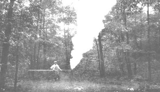
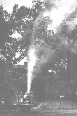
Figure 1 shows a method of applying smokes, using a combustible fuel for heat energy. Arsenicals, rotenone, pyrethrum, nicotine, and oils were applied with this method in experiments by S. F. Potts and D. F. Barnes from 1927 to 1929 under essentially all conditions. The deposit out-of-doors averaged only about 2 percent as great as when the same quantity of insecticide was applied by hydraulic sprayer. Efforts to increase the particle size were not very successful, because when particle size was increased enough for deposition the particles were not projected more than a few feet from the applicator.
FIGURE 1. - Smoke aerosol aerosol to gypsy moth infested woodlands.
Dust particles may be coated in the air by small droplets of oil, if the mixing takes place either in a vacuum or under pressure.
Liquefied gas aerosols have a field of potential use that is more restricted than for concentrated sprays, hut is far greater than that for smokes.
Fine atomization is necessary to obtain adequate distribution with low gallonage hut the droplets must he large enough to deposit on foliage and insects. Apparently for ground application most of the spray should he in droplets 30 to 80 microns in diameter. For aerial application most of the droplets should be 70 to 100 microns in diameter if the areas are large and flat, and as large as 100 to 300 microns for the control of certain forest insects on rugged terrain.
The number of droplets of given size that would he deposited per unit area per gallon of liquid distributed on an acre of surface is presented. Smoke aerosols give a very low residual deposit.
Some factors affecting particle or droplet size are: type of distributing device, pressure, nozzle design, orifice size and shape, air velocity; spray concentration, density, type of insecticide, surface tension, viscosity of the mixture, rate of volatilization of the ingredients, distance to which the particles must be drifted, wind and other meteorological factors, volume and compactness of foliage, and settling rate.
The data given in the text and tables that follow are from hundreds of tests and replicates and thousands of samples, and droplet measurements made in an intensive and extensive study of this subject during each of the past 10 years. The data and information presented are those of the author, except when indicated otherwise.
Table 3 lists the water output of cone and solid-stream nozzles for given orifice diameters and pressures. The proper use and setting of these nozzles will be given later under equipment construction and use. It is important to note that atomizing cone-type nozzles with 80° included angle only deliver 30 to 40 percent as much liquid as solid-stream orifices of the same diameter and pressure. The output decreases as the angle of spread is increased from 0 to 180 degrees. The Hat or fan-type nozzles deliver theoretically the same output as the solid-stream orifices. Actually, most of them deliver about 10 percent less liquid than solid-stream orifices due to resistance from the restricting walls of the nozzle tip located just beyond the orifice. In general, rate of output increases or decreases as the square root of the pressure. For example, a given orifice delivered 5, 7.07, and 10 gallons per hour (g.p.h.) at 25, 50, and 100 pounds per square inch (p.s.i.).
Viscosity and surface tension are sometimes factors in the output of liquid as related to temperature. For example, at room temperature the output of five direct pressure nozzles ranged from 5 to 12 percent greater than for water when applying kerosene and oils of 30 to 35 seconds Saybolt viscosity. At 40 seconds viscosity, the flow of the water and oils was equal. At 50 seconds viscosity, the rate of flow of oils was 85 percent as fast as for water, and at 100 seconds viscosity the oils would not flow properly through orifices smaller than 3/32 inch.
However, when made up as 25 percent oil emulsions, oils of 100 to 200 seconds viscosity flowed at about the same rate as water. At temperatures of 30°F or lower, oils of 60 seconds viscosity or greater would not flow properly through nozzles.
TABLE 3. - Output of cone and solid stream type nozzles for given orifice diameters and pressures
|
Orifice diameter, in hundredths of an inch |
Output as a solid stream at 50 p.s.i. |
Output as 70 to 80° cone a spary at:b |
||
|
25 p.s.i. |
50 p.s.i. |
100 p.s.i. |
||
|
Gallons per hour |
||||
|
1 |
1.1 |
|
|
0.5 |
|
2 |
4.4 |
1.0 |
1.45 |
2.1 |
|
3 |
9.9 |
2.3 |
3.24 |
4.6 |
|
4 |
17.6 |
4.1 |
5.76 |
8.1 |
|
5 |
27.5 |
6.3 |
9.0 |
12.6 |
|
6 |
40.0 |
9.1 |
13.0 |
18.3 |
|
7 |
54.0 |
12.6 |
18.0 |
25.3 |
|
7.8 |
66.0 |
15.4 |
22.0 |
30.8 |
|
8 |
70.4 |
16.1 |
23.0 |
32.2 |
|
9 |
89.1 |
20.5 |
29.3 |
42.0 |
|
10 |
110.0 |
26.3 |
36.3 |
51.8 |
|
12.5 |
172.0 |
39.2 |
56.0 |
78.5 |
|
15 |
248.0 |
57.0 |
81.0 |
114.0 |
|
17.5 |
337.00 |
77.0 |
110.0 |
154.0 |
|
20 |
464.0 |
101.0 |
144.0 |
202.0 |
|
25 |
688.0 |
158.0 |
225.0 |
315.0 |
|
37.5 |
1547.0 |
355.0 |
506.0 |
709.0 |
|
50 |
2750.0 |
630.0 |
900.0 |
1260.0 |
a At outputs below 3 gallons per hour (g.p.h.) the included angle was less than 80 degrees, depending somewhat on pressure.
b Divide by 60 to find the gallons per minute (g,p.m.).
To obtain maximum efficiency of pest control while maintaining the greatest degree of safety for plants requires optimum drop size and velocity for best coverage and deposition on leaves, needles, twigs, and insects at given distances vertically or horizontally from the blower. The penetration and coverage of dense foliage requires a smaller particle size and greater air velocity than for sparse foliage and dormant trees. AS the size of the particles decreases there is a corresponding need for increasing the air velocity in order to impinge the droplets. Solution for this problem is made more difficult by the fact that air velocity decreases as distance from the blower increases, which creates the need for increasing particle size with increase in distance from the blower in order to effect impingement of the drops. Insofar as is practical, formulations should be used that do not volatilize rapidly and thereby reduce the particle size in the air.
Two sets of figures were developed in an endeavor to determine the optimum drop size. One set of figures are theoretical calculations based on Sell's (1931) studies of the deposition of particles in a moving air stream and on Stoke's law (Miller, 1935) showing that particles fall with a velocity depending on their diameter or surface area and specific gravity. The other figures are from practical field tests.
Sell's formula for calculating the minimum air velocity for maximum deposit is as follows:
 where,
V1 = minimum velocity for maximum deposit in m.p.h.
S = width of object in inches
D = diameter of particles in microns
The upward air velocity required to overcome rate of fall can be computed from the formula:
V2 = 0.0000605 D2 where,V2 = Velocity of air in m.p.h. to overcome gravity oil spray weighing 7.8 lb. per gal.
D = diameter of particles in microns.
Increasing or decreasing the specific gravity of the spray solution directly increases or decreases the air velocity required to overcome the gravity of drops.
TABLE 4. - Air velocity required to overcome gravity of drops having a specific gravity of 1.00, applicable to vertical projection
|
Diameter, of drops in microns |
12.5 |
25 |
50 |
75 |
100 |
125 |
150 |
175 |
200 |
300 |
|
Velocity V2 of air to overcome gravity, in m.p.h. |
0.01 |
0.044 |
0.018 |
0.38 |
0.67 |
1.06 |
1.51 |
2.06 |
2.7 |
6.0 |
The minimum air velocity (V1) required for deposition varies inversely with the drop size and the air velocity (V2) required to overcome gravity. When these two are added the theoretical optimum drop size can be found for objects of various size.
TABLE 5. - Minimum air velocity for efficient deposition with elevation for droplets and objects of various size
|
Width of objects in inches |
Particle size, in microns diameter |
||||||||
|
25m |
50m |
75m |
100m |
125m |
150m |
175m |
200m |
300m |
|
|
Miles per hour |
|||||||||
|
½ |
4 |
1.2 |
0.7 |
0.8 |
1.0 |
1.4 |
1.6 |
1.8 |
5.5 |
|
¼ |
8 |
2.2 |
1.2 |
1.1 |
1.3 |
1.6 |
2.0 |
2.5 |
5.7 |
|
½ |
16 |
4.2 |
2.1 |
1.6 |
1.6 |
1.8 |
2.2 |
2.7 |
5.8 |
|
1 |
32 |
8.2 |
3.9 |
2.6 |
2.2 |
2.3 |
2.5 |
2.9 |
5.9 |
|
2 |
64 |
16.2 |
7.5 |
4.6 |
3.5 |
3.1 |
3.2 |
3.4 |
6.0 |
|
3 |
96 |
24.2 |
11.0 |
6.6 |
4.8 |
4.0 |
3.8 |
3.9 |
6.1 |
|
4 |
128 |
32.2 |
14.6 |
8.6 |
6.0 |
4.9 |
4.6 |
4.4 |
6.2 |
|
8 |
256 |
64.2 |
28.0 |
16.0 |
11.0 |
8.0 |
7.4 |
5.4 |
6.3 |
The mist blower is the most interesting of the spray machines because it embodies the principles of all types of ground equipment and many of the principles of aircraft as well; they have a wider variety of uses and adaptations than other types. They have not had the volume of use enjoyed by the nonblower type low gallonage rigs, for only a small section of potential users are familiar with them.
The specific requirements and attachments for blower type applicators vary considerably with the kind of growth and size of areas to be treated. Table 6 indicates nine approximate sizes and capacities for general uses.
Fans and outlets
In mist blowers, the fan is the "heart" of the machine just as the pump is the "heart" of the hydraulic sprayer. Two methods of application characterize the use of fans as follows:
1. a high velocity of air at 185 to 300 m.p.h. to atomize and project the spray;2. the use of a combination of medium high air velocity of 90 to 185 m.p.h. and hydraulic pressure nozzles or centrifugal spinner nozzles, to break up the spray and distribute it.
TABLE 6. - Horsepower, weight, and air capacity of mist blowers
|
Horse power requirement |
Weight, in pounds |
Air velocity, miles per hour |
Air volume (cu. ft. per min.) |
Preferred mounting |
|
1.5 to 2 |
90-100 |
225 |
150 |
Wheelbarrow pick-up truck, trailer, small tractor |
|
4 to 5 |
300 |
180 |
800 |
Trailer, truck, tractor |
|
7 |
500 and 200a |
175 |
1700 |
Trailer, truck big tractor |
|
12 |
600 and 300 |
145 |
3600 |
Trailer, truck, tractor |
|
15 |
700 |
145 |
4000 |
Truck, trailer, big tractor |
|
25 to 30 |
1800 to 2000 |
135 |
8000 |
Truck, tractor-drawn trailer |
|
40 to 50 |
3000 |
125 |
12000 to 15000 |
Truck, tractor-drawn trailer |
|
25 |
2000 |
80 to 100 |
19000 |
Truck, tractor-drawn trailer |
|
75b |
4000 to 5000 |
120 |
24000 to 30000 |
Tractor-drawn trailer |
a Weight of 200-300 lb. refers to use with light two-cycle engine.
b For discharging from both sides of machines
There are two general types of fans, the axial flow and the centrifugal So-called curved blade, squirrel cage or multivane, Soroceo, and multiple stage fans are merely modifications of these two types. No specific type of fan is best for all conditions, for a given fan may influence the design of a machine favorably for some jobs and unfavorably for others.
Belt drives, and some direct drives, have been successful. Weakly constructed right angle gear drives always break down. However, a strong, specially constructed right angle drive can be made to work on a strong, steady frame. Fans should be steady and as free of noise as possible.
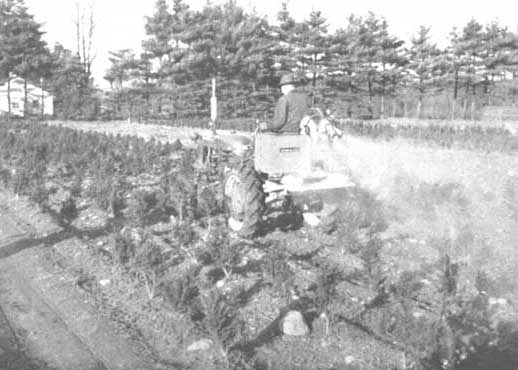
The principal factors determining the type of fan to use are the air velocity required to break up and deposit the spray, the size of the machine, and whether the outfit is to be operated by one man or two men. In general, very small rigs (Figures 2 and 3) utilize high velocity air to break up the spray by shearing action. Hence, they may use high velocity, low volume, single or double stage fans. Usually the medium to medium-large rigs employ a combination of air velocity of 125 to 150 m.p.h. and hydraulic pressure of 150 p.s.i. or less, through whirl nozzles to atomize the spray. Machines of this type usually have delivered about 4,000 to 10,000 cubic feet per minute (c.f.m.) of air by either of the two types of fans. (Figures 5 and 6).
Courtesy, Connecticut Agr. Expt. Stn. New Haven, U.S.A.
Machines of very high volume and low velocity may require a small, high velocity, low volume auxiliary blower to break up the spray and distribute it into the air stream from a big fan or they may atomize the spray with whirl or fan type nozzles at 200 to 600 p.s.i. For most forest and shade tree work, air velocities of 120 to 150 m.p.h. are required in volumes of at least 8,000 c.f.m. Volumes of 12,000 to 15,000 c.f.m. at velocities of 120 to 135 m.p.h. are preferred, or 18,000 to 26,000 c.f.m. of air at 95 to 115 m.p.h., for 70- to 120-foot trees, especially where elm bark beetles and certain other pests in the tops of the trees are to be controlled.
There is an optimum ratio between velocity and volume at the orifice to attain the greatest height and distance with a given horse power under operating field conditions. The volume of air delivered is directly proportional to the square of the diameter of the outlet. Thus, a 24-inch outlet delivers four times as much air as one 12 inches in diameter at the same velocity. In shade tree work the optimum velocities for various sized outlets are given in Table figures in Table 7 do not correspond exactly to those of Table 6, due primarily to a slight difference in outlet size, nor do the figures correspond with those of Table 8, since Table 8 represents the actual machine in use while Table 7 represents the optimum conditions.
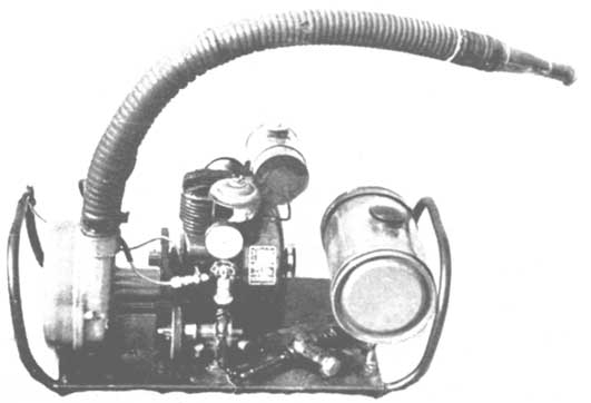
In small machines like the wheelbarrow model, a much higher air velocity (200 to 300 m.p.h.) has been employed because air velocity provides the means of atomizing the spray (Figure 3).
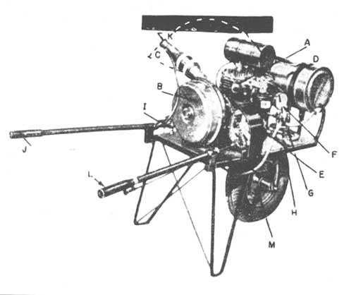
FIGURE 3. - Wheelbarrow mist blower.
The 1.5 h.p. engine (A) drives the high pressure blower (B), with a capacity of 120 cubic feet of air per minute, at approximately 240 M.p.h. velocity as it leaves the 1¼ inch diameter nozzle (C). Concentrate in the 3-gallon tank (D) is kept in suspension by agitation provided by an extra line from the pump. Pressure is maintained by pump (E), the belt is driven from the engine, and shown by gauge (F), and regulated at valve (G) at about 5 pounds. Clear lines are assured by strainer (H) between the tank and the pump. All hose is of neoprene rubber, resistant to oil concentrates. From the pump the concentrate goes through the "on-and-off" valve (I), controlled by twisting left handlebar grip (J) and continues to the end of the nozzle. It enters the hollow circular tip of nozzle (K), which has four outlets with 1/6 inch holes projecting into the airstream from the blower. This high velocity airstream atomizes the concentrate and carries the mist in whatever direction the nozzle is pointed. The up-and-down direction of the nozzle is controlled by twisting the grip (L) on the right handlebar. It travels in a 200° arc, and so can spray on either side. Moving the sprayer to the next spot is almost effortless, as the 140 pounds is so carefully balanced on the large 16-inch high wheel, with its 4-inch pneumatic tire. Thus one man can handle the entire spraying operation.
In the large machines spray delivery should be calibrated to permit regulation of any specified delivery between 20 and 180 gallons per hour (1/3 to 3 gallons per minute) (Figures 6, 7 and 8).
TABLE 7. - Optimum velocity and volume for round outlets of given diameter for tree application. a
|
Diameter of outlet inches, |
Optimum velocity m.p.h. |
Volume c.f.m. |
|
4 |
170 |
1300 |
|
8 |
150 |
4200 |
|
10 |
145 |
6300 |
|
10.5 |
140 |
6300 |
|
12 |
130 |
8000 |
|
15 |
126 |
b |
|
18 |
123 |
b |
|
20 |
120 |
21000 |
|
24 |
115 |
27000 (approx.) |
a This is orifice velocity. Deposition velocity is much less.
b Figures not available.
The size, shape, and flexibility of the outlet are important. For the small machines that deliver high velocities a very flexible outlet is essential to obtain even coverage. The round short outlet is the most efficient shape for shade tree and mosquito work where the fine spray must be driven to great distances. For the large, one-man operated orchard machines some air and power efficiency must be sacrificed in order to effect sufficient spread close to the machine. This spread may be obtained with slot or fishtail outlets with spreader vanes or spoilers, or with multiple round ones.
Air speed at given distances from a fan depends on eight factors as follows:
1. air velocity;2. air volume;
3. diameter of round outlet, width of fish tail, or slot outlets;
4. shape of outlet and angle of spreader deflectors;
5. the temperature of the air, moisture, content and weight;
6. upward or downward air currents;
7. wind velocity and direction in relation to direction of discharge from blower;
8. rate of travel of machine: travel reduces distance and air speed: two m.p.h. travel is equivalent to a 5-mile wind.
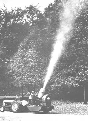
FIGURE 6. - A 30-horespower mist blower mounted on a turntable for treating tall trees.
TABLE 8. - Variations in spray delivery for the different sized air outlets
|
Outlet diameter inches |
Spray delivery, gallons per hour |
|
|
Range |
Efficient for most purposes |
|
|
1.25 |
5 - 15 |
7 |
|
2 |
10 - 25 |
14 |
|
4 |
15 - 40 |
20 |
|
10 |
20 - 72 |
40 |
|
12 |
25 - 120 |
50 |
|
15 |
30 - 150 |
60 |
|
18 |
35 - 168 |
70 |
|
20 |
40 - 180 |
80 |
|
24 |
45 - 180 |
90 |
The flexibility of the outlet may determine the type of fan to use for highest operational efficiency. For example, certain axial flow fans are more efficient in moving air straight away from the fan than the paddle or centrifugal type fans. However, to use axial flow fans in forest and shade tree work, it is necessary to expend some horse power in forcing a direction change in the air stream, if the fan and outlet cannot be rotated together. On the other hand, some of the paddle or centrifugal fan cases with straight short outlets can be rotated or easily swung up and down in a 180 to 230 degree arc with no loss of air efficiency. This operation, and a 180 degree (half turn) turntable is sufficient to take care of the others. This provision also permits making the rig shorter, more flexible, simpler, and more efficient in operation.
TABLE 9. - Air velocities at given horizontal distances from blowers, delivery through round outlets of given diameter a
|
Diameter of outlet (inches) |
Approximate volume (c.f.m.) |
Velocity (m.p.h.) at the following distances from blower |
|||||||
|
At blower outlet |
10 feet |
25 feet |
50 feet |
75 feet |
100 feet |
150 feet |
200 feet |
||
|
1 |
140 |
300 |
15 |
2 |
0 |
0 |
|
|
|
|
1.25 |
200 |
225 |
20 |
3 |
0 |
|
|
|
|
|
2 |
370 |
200 |
30 |
5 |
1 |
0 |
|
|
|
|
4 |
1300 |
170 |
40 |
8 |
2 |
0.2 |
|
0 |
|
|
8 |
3800 |
125 |
40 |
10 |
3 |
1 |
0 |
|
|
|
10 |
6100 |
140 |
70 |
36 |
6 |
3 |
1.8 |
0 |
|
|
10.5 |
6300 |
140 |
75 |
40 |
7 |
3 |
2 |
0-1 |
|
|
12 |
7500 |
125 |
60 |
30 |
7 |
4 |
2.5 |
1 |
0 |
|
24 |
20000 |
90 |
50 |
25 |
7 |
6 |
4 |
2 |
0 |
|
24 |
28000 |
120 |
76 |
40 |
17 |
10 |
9 |
7 |
3 |
|
54b |
27000 |
60 |
35 |
30 |
8 |
4 |
3 |
2 |
0 |
a Air gauges used were: 1. a gauge for measuring air velocity in terms of inches of water pressure, 2. an airplane pressure gauge, 3. low velocity gauge, and 4. an anemometer.
b Not an enclosure outlet.
The machines was equipped to apply duos, aerosol, spray-dust and atomized concentrates. The nozzle assembly is ouch as to fill the air stream. The large outlet and velocity control makes possible a wide spray stream. A small amount of dust was added to facilitate photographing.
FIGURE 8. - A truck-mounted mist blower treating an 70-foot elm tree in the dormant season.
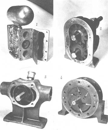
Pumps
There are three general kinds of liquid pumps and diaphragm pumps which may be used: plunger, centrifugal, and gear. Plunger and diaphragm pumps can deliver any kind of mixture at any pressure. They are heavier and more expensive, but if kept in repair are more durable than gear types. Metal centrifugal pumps can deliver any kind of mixture at low pressures (below 40 p.s.i.). Spur-type gear pumps can deliver up to 150 pounds pressure at 1,200 to 2,000 r.p.m. (revolutions per minute). Ordinarily, abrasives like sulphur and cryolite will wear off the gears at such high speeds and pressures that present types of gear pumps do not last long when applying such abrasive substances at high speeds with pressures above 15 to 20 pounds. However, at pressures of 2 to 15 pounds and at speeds of 360 to 700 r.p.m., good ones may last one to three years. They are usually more satisfactory than centrifugal pumps for most mist blowers. For the small machines a 1/4 inch gear pump is adequate; however, large rigs may require a 3/8 inch or 3/4 inch gear, or a 2- to 4-gallon-per-minute plunger pump (Figure 10).
FlGURE 9. - Four types of pumps.
The pumping systems require oiling, suitable liquid bypass arrangements, relief valves, and pressure gauges with diaphragms to keep the liquid from entering the gauges. Gear pumps without "built in" pressure relief regulators are preferable for general use. To pump at specified low pressures, a suitable relief valve and large capacity by-pass are essential. Steady pressure without pulsations is essential in all spray systems.
Washers, gaskets and hose
All washers, gaskets, and hose must be resistant to oil solvents. Disintegrating rubber parts in the line can plague the operator continuously by repeatedly plugging the nozzles. Leather washers and neoprene hose (such as Weatherhead hose) and some plastics are more resistant than natural rubber products. It is expected that some of the new plastic materials may replace rubber materials.
Tanks and agitators
Supply tanks should be of the proper size and shape. This depends on the capacity of the machine and the nature of application. On big machines 40- to 75-gallon tanks are suitable for shade tree spraying, but 75- to 300-gallon tanks are desirable for fruit trees. A round or trough-shaped bottom with a mechanical agitator is desirable for mixing any kind of material, and for agitation. By-pass agitation is insufficient. Paddle type agitators should move slowly, sweep the bottom, and be provided with a disengaging mechanism. Spiral blade agitators may move faster. For filling purposes, tanks should have a wide mouth provided with 12- 16-mesh removable strainer. It is helpful to have a quantity gauge for reading the volume of mixture in the tank. The tank metal should be noncorrosive, and any paints applied to it should be able to withstand oil solvents and ordinary spray chemicals.
The construction must enable the operator to drain the tank and spray line quickly and completely. Hence a large tank drain plug should be located conveniently. Sometimes it is handy to he able to connect a hose to the drain plug connection to convey the waste solution to a disposal spot. It is important to avoid strainer wells in the tank's bottom. It is also, important to be able to shut off the tank from the spray line at a point immediately below the tank to prevent spray material from settling down into the spray line, strainers and nozzles.
Other construction details
Screw type valves should not be installed except for regulating pressure or liquid to be by-passed. A quick-acting shut-off valve operated by a foot or hand lever is absolutely essential. It must be conveniently located so that the operator can use both hands simultaneously for "finger touch" manipulation of outlet and liquid and dust shut-off levers. It should also permit him to observe the spray operation continually without changing his line of vision.
One large surface area strainer of approximately 16 mesh should he located between tank and pump. A 20-mesh strainer of smaller size should he placed in the line between pump and nozzles. All coarse mixtures prepared outside of the machine should he poured through a strainer in the top of the spray tank. Many modern spray materials of small particle size, however, do not require it.
Some means of measuring and regulating the quantity of spray material delivered per minute, per tree, per given area, or per given distance of travel is helpful. Hence, there is a definite need for at least one of three types of meters: a flow meter, a time (dial) meter, and a distance or low speed speedometer to measure rates of travel between 0 and 6 miles per hour.
The turntable may be power-driven by hydraulic motor or electric motor equipment with generator; or the machine may be turned by the operator pushing the unit around with his feet while in the seat of the machine, or with a wheel and cable. The latter is the cheapest and simplest method. The turntable should be provided with a good hand- or foot-brake.
In spraying forests for control of brush and hardwoods, 6 to 16 h.p. mist blowers are mounted on crawler type tractors. For shade tree and mosquito spraying, the machine is usually mounted on a truck with wide tires to reduce damage to lawns. For treating orchards, it is usually drawn on a trailer.
For night work a good spotlight can be mounted on the rotating outlet head or heads.
A throat microphone, or preferably a two-way chest microphone is useful for communication between operator and driver. The throat microphone costs less than 10 dollars, and consists of earphones, four 11/2 volt dry batteries, a rubber covered, two-strand wire, and throat microphone.
Mist blower specifications for tall forest and shade trees
Air volume. 8,000 c.f.m. or greater, depending on velocity.
Air velocity. 152 m.p.h. or greater for air volume of 8,000 to 10,000 c.f.m.; or 90 to 110 m.p.h. for air volumes of 20,000 to 30,000 c.f.m.
Diameter of outlet. 12 inches or greater, depending on air volume.
Pump. To deliver at least 2 gallons per minute. A plunger pump or a diaphragm pump is satisfactory for all mixtures and is preferred where wettable powder suspensions are to be applied at high pressure. A gear pump is satisfactory if only solutions and emulsions are to be used. A ½ to 1-inch gear pump is acceptable for wettable powders if pressures less than 20 pounds are used provided the pump turns less than 750 r.p.m. to reduce abrasiveness.
Delivery regulation. 1/5 g.p.m. to 2 g.p.m. with or without metering device.
Engine. Usually over 20 h.p., depending on performance.
Tank. 40 gallons or greater capacity, with suitable drain plug, and coated with material that is resistant to rust, corrosion, acids, and solvents.
Agitator. Mechanical agitation is preferred, especially where suspensions are to be used.
Outlet rotation. 210° arc is sufficient. Easily rotated mechanically or by hand.
Turntable. Required with a brake and capable of making a 360 degree turn easily. Must be convenient for oiling, changing points, spark plugs, etc.
Shut-off valve. Quick-acting type, conveniently located to operator.
Turning diameter. Less than 9 feet.
Floor space. Less than 73 x 73 inches.
Weight. Less than 3,000 pounds.
Strainers. Suitable 16 to 20 mesh strainer for suspensions is necessary.
Atomization. Capable of producing mass average diameters between 35 and 80 microns diameter.
Construction. Sturdy, durable, simple, easily operated, adaptable, and easily repaired and transported.
Location of seat and operator. Must be remote from the heat of the engine's exhaust and from leakage of air and spray material.
Mounting. For available trucks or mounted on a trailer.
Performance. Must meet efficient performance requirements for the jobs intended in addition to the above specifications.
A sheet of instructions on methods of operation and maintenance must be supplied with the machine.
Compressed air sprayers
These are so named because air is compressed in the tank above the liquid. The essential parts are a tank (usually cylindrical) for spray material, with carrying handle or shoulder strap, pressure-tight filler cap, air pump for compressing air in tank, discharge tube which conveys the liquid in the tank to the discharge system consisting of hose, extension spray tube, spray control valve, strainer and nozzle. They are cheaper, easier to clean, and more popular than the handle-operated diaphragm or piston pump knapsack sprayers. Compressed air sprayers are normally operated with 25 to 50 pounds air pressure on the liquid.
For special uses requiring a specified constant pressure, an auxiliary air tank is required with intake valve and a constant pressure regulator between the air tank and the liquid tank.
Some models have CO2 gas cylinders to provide operating pressure. They discharge up to 15 gallons of material at uniform spraying pressure. Refilling cost is moderate. Use of the compressed gas permits utilizing the full capacity of the tank for spray material.
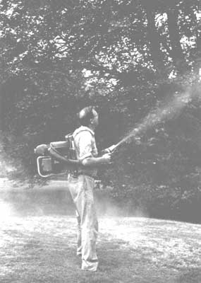
Knapsack sprayers
Knapsack sprayers, as the name implies, are carried on the back like a knapsack by means of two shoulder straps (Figures 10 and 11). The tank is shaped to fit the back, but is not always comfortable. Some makes have built-in liquid pumps of diaphragm or piston type which the operator pumps continuously while spraying. A pressure chamber reduces pulsations. Other models are provided with a double-acting external slidetype pump. Top pressures range from 80 pounds for the internal type pump to 175 pounds for the slide type pump. Operation of the pump provides a mild form of mechanical agitation that is not sufficient for wet-table powder mixtures without occasional shaking. Pump handles may be attached at either side to permit right or left hand spraying.
Most knapsack sprayer tanks are made of galvanized steel but some models are available in copper or stainless steel at additional cost. Tank capacities range from 4 to 6 gallons.
The ordinary back, fire pumps are not suited for applying concentrated sprays.
The common faults of present-day compressed air and knapsack sprayers are listed below together with some suggested remedies for manufacturers and users of such equipment:
1. The hose is too short. A length of 4 to 5 feet is needed to provide reach and leverage.2. Sore backs are often caused by poor back protection and leakage through the tops of knapsack sprayers. This is particularly serious when applying certain solvents and poisons. Proper back fits, padding, and tight covers would help.
3. Gaskets and plunger rubbers and packings are readily decomposed by solvents such as xylene, oils, and various other chemicals. Sprayers should be equipped with resistant materials.
4. Some sprayers do not discharge all of the mixture in the tank.
5. Most sprayers are not equipped with durable, dependable shut-off valves that do not leak.
6. Poor agitation.
7. The tanks tend to corrode and rust. This can be prevented by coating the inside of the tank with a protective material and by prompt cleaning and drying.
8. Extension rods longer than 3 feet are too heavy. A lightweight metal, such as magnesium, should be used. If it is still too heavy, the extension rod should be strapped on a bamboo pole or placed inside of it by running the rod through a hole drilled the length of the pole.
(To be concluded)
![]()
![]()
![]()