![]()
![]()
![]()
ROLAND ROTTY
Forest Service, United States Department of Agriculture
In order to make this manual useful for a wide range of nursery situations, information regarding methods and machines applicable to several levels of mechanization are included in it. For example, where possible, descriptions are given of equipment suited to the largest of nurseries, to moderate-sized ones, and to those without self-powered equipment. Alternate methods of accomplishing the same thing under different conditions are often discussed. It is hoped that presentation in this manner will enable a user of the manual to choose practices that will best suit his local conditions, and to decide which operations he will mechanize and which he will continue under time-honored, hand-labor methods. The author makes grateful acknowledgment of the contributions of many nursery administrators and their associates in allied fields in the United States and a few in Canada. Much of the material used was taken from articles prepared by these men and published in various issues of Tree Planters' Notes, a publication of the Forest Service, U.S. Department of Agriculture. Considerable material has also been taken from Planting the Southern Pines by Philip C. Wakeley, Agriculture Monograph No. 18 (1954), and Forest Nursery Practices in the Lake States by J. H. Stoeckler and G. W. Jones, Agricultural Handbook No. 110 (1957), both published by the Forest Service, United States Department of Agriculture.
No step in artificial reforestation requires more care than does selecting the site for a permanent nursery. Good nursery sites are likely to be superior, high-price farmland. Experience has shown that buying a good site may cost far less than correcting unsuitable conditions on a poor one.
A central location within the territory served by the nursery minimizes stock-shipping costs, and access to main highways, express and freight facilities, water, telephone service, labor, electric power, and cold storage are important considerations. Medical, school, and similar facilities for the nursery staff are also important.
Localities of serious insect and disease hazard, including sites infested with harmful soil fungi or nematodes, should be avoided. Determination of insect, fungous, or nematode infestation usually requires not only field examination but also laboratory and greenhouse testing and a thorough study of the past history of the site. The existence of quarantine lines that would prevent or hamper shipment of stock should be checked.
The acreage required depends on the age and species of trees to be grown, which in turn depends upon the climate of the area being reforested. In regions with a long growing season, most of the species used for reforestation will attain field-planting size in a single growing season, but in regions with a shorter season and slower growing species, from 2 to 5 years are needed to produce satisfactory field-planting stock. The acreage of nursery land required to meet an annual production quota, therefore, is a matter of arithmetic that takes into account species, season, and proper consideration of the fact that enough land must be provided to permit rotations of trees and soiling crops.
As shown in Table 1, approximately a million conifer seedlings can be produced on an acre with seedbed densities of 30 plants to the square foot. Transplanted conifers in beds with 6-inch row spacing will approximate 400,000 plants an acre. Lined-out hard-wood trees will produce 150,000 usable plants an acre.
TABLE: 1. - AREA1 REQUIRED FOR 1,000,000 CONIFER SEEDLINGS AT DIFFERENT COMBINATIONS OF BED AND PATH WIDTH AND SEEDLING STAND DENSITY
|
Seedlings per square foot |
3-foot beds |
4-foot beds |
5-foot beds |
|||
|
2-foot paths |
1 ½ -foot paths |
2-foot paths |
1 ½ -foot paths |
2-foot paths |
1 ½ -foot paths |
|
|
Acres |
||||||
|
20 |
1.91 |
1.72 |
1.72 |
1.58 |
1.61 |
1.49 |
|
25 |
1.53 |
1.38 |
1.38 |
1.26 |
1.29 |
1.19 |
|
302 |
1.28 |
1.15 |
1.15 |
1.05 |
1.07 |
0.99 |
|
35 |
1.09 |
0.98 |
0.98 |
0.90 |
0.92 |
0.85 |
|
40 |
0.96 |
0.86 |
0.86 |
0.79 |
0.80 |
0.75 |
|
45 |
0.85 |
0.77 |
0.77 |
0.70 |
0.71 |
0.66 |
|
50 |
0.77 |
0.69 |
0.69 |
0.63 |
0.64 |
0.60 |
1 Including beds and the paths separating them, but not roads, cross paths, or width added to paths along sprinkler lines.2 Practicable average density on most nursery soils.
To insure against unforeseen losses, the total area of seedbeds and paths allowed for a given number of seedlings should be about 20 percent greater than the net area required at the desired seedling stand density. This total must, in turn, be doubled if it is so planned that soil-improving crops are to be alternated annually with seedlings.
Space must be allowed for roads and buildings, and for increases in seedbed area if the planting program expands.
A prime need is a dependable water supply large enough to lay down the equivalent of 4 or 5 inches of rainfall a month over any area likely to be used for conifer Seedlings. A rate of flow sufficient to apply one-half inch of water over the entire seedbed area in 12 hours or less is desirable. Five inches of water on 1 acre - ordinarily the minimum area to produce a million seedlings - requires 136,000 gallons. Residences, shops and offices, and the fire protection system require additional amounts.
Water carrying 500 parts of calcium per million is likely to raise the pH concentration in nursery soil and to increase damping-off, root rot, and chlorosis; water carrying 100 parts of CaCO3 or 125 parts of calcium bicarbonate per million may do so. Water with a high silt or colloidal content may seal the soil surface, reduce soil aeration, and predispose seedlings to disease; the water itself may carry disease organisms. Sediment or algae in the water may clog sprinkler nozzles unless screened out.
No nursery should be established until analysis shows that the available water is free from, or can readily be freed from, harmful substances and organisms. It is well to test the water in advance of nursery establishment for a full growing season, both to see whether regular applications increase the pH concentration of the top one quarter to one half inch of soil over that of soil three inches down and of topsoil in unwatered plots, and to learn what is their effect on seedlings in plots or pots.
Sites with excessive surface drainage and erosion should be avoided. Ordinarily the slope of the seedbed area should nowhere exceed 2 or 3 percent, yet the site must not be absolutely flat in order that water does not stand after rain. Subsurface drainage is as important as surface drainage. Land subject to overflow is useless.
The soil should be uniform in depth and texture as well as in slope. The best nursery soils are fine to coarse sandy loams underlain at 18 inches or slightly more by somewhat stiffer but still permeable subsoils. A stiff subsoil less than 12 inches below the surface is very undesirable.
Soils containing not less than 15 percent nor more than 25 of particles smaller than 0.05 millimeter in diameter are recommended. Such particles generally remain suspended in water when soil is mixed with water in a partly filled flask, shaken hard 60 times, and allowed to stand for 60 seconds. The larger particles settle to the bottom of the flask. More accurate special techniques and apparatus are, of course, available for such measurements. The lighter soils are better drained and easier to work than heavy soils, and permit better seedling root development. However, extremely light, loose, sandy soils (low in organic matter and with poor moisture-retaining capacity-wilting coefficient less than 4 percent) should be avoided. Those that are easily eroded by wind or water, that puddle, cake, or crust after wetting, or that contain much stone or gravel should also be avoided.
The pH concentration of the soil should not be above 6.5 nor below 4.5. At the higher levels, the seedlings may suffer from damping-off, root rot, and chlorosis, and at the lower levels mineral nutrients may be rendered unavailable to them.
The mineral nutrient level of nursery Boils should be at least as high as that required for agricultural crops grown on former pine land, and should be capable of easy maintenance and improvement. The great weight of plant tissue produced when seedlings are grown at ordinary seedbed densities, together with its practically complete removal during lifting, makes the drain of seedling crops upon soil nutrients severalfold that of cotton or corn.
It is thought that the organic content of nursery topsoil should not be below 1.5 percent, preferably not below 2.5 percent.
The presence of abundant mycorrhiza-forming fungi in the soil appears desirable.
If there is a choice of site, weedy areas should be avoided, especially those infested with heavy weed growth. Luxurious weed growth, however, usually indicates high soil fertility, and meager weed growth, low fertility.
The soil is the hardest thing about a nursery site to evaluate. The most dependable way is to grow several small trial beds of seedlings for I year, and preferably for 2 years, before the site is developed. At least one such test crop should be outplanted on average to fairly severe sites to see how the seedlings survive the first year.
As planning for a new nursery begins, the first decision that must be made is the nature of the irrigation system that will be used. This must definitely be decided before any plans for layout, grading, or anything else can be fixed.
Whether the nursery is irrigated by sprinkler lines, garden hose, ditches, or flood, depends upon local circumstances. Each system has certain advantages of convenience, cost, and performance. They are described below.
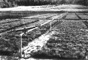
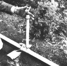
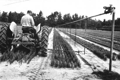
Many nurserymen prefer an irrigation system that uses permanently installed horizontal sprinkler lines equipped with hydraulically powered oscillators. The lines in Figure I are about 3 feet above the ground. To avoid damage from freezing, this installation has a shut-off valve of the stop-and-waste type beneath the ground surface to permit automatic drainage of the riser. If automatic protection from freezing is not needed, an ordinary valve between the riser and the oscillator would be a less expensive and more convenient installation. Hose-bib faucets installed in occasional risers is also a desirable convenience (Figure 2).
FIGURE 2. - Construction details for horizontal sprinkler system. - Courtesy, Forest Service, U.S.D.A.
|
A. |
To avoid strain and malfunction of oscillator, use 2 street ells in place of one standard ell if slope of land will not allow line to be 900 angle to riser |
|
B. |
Automatic oscillator, Skinner type " C " or equivalent |
|
C. |
Galvanized steel sprinkler pipe, sizes as shown on plan |
|
D. |
Hand-flush valve threaded, for ¾ in. hose |
|
E. |
Brass gate valve |
|
F. |
Quick acting couplings |
|
G. |
Rust-proofed brass roller wheel pipe hanger |
|
H. |
2 × 2 × ¾ in. tee with hose bib on alternate risers, staggered on adjacent blocks |
|
I. |
Height controlled by personal preference |
|
J. |
Wood post or iron pipe |
|
K. |
Roadway |
|
L. |
2 in. galvanized, riser, typical |
|
M. |
Ground line |
|
N. |
Line to risers on other side of roadway |
|
O. |
Slope |
|
P. |
Tapped iron cross if main is to serve risers on both sides of roadway |
|
Q. |
2 in. - 90° long sweep ell |
|
R. |
2 in. galvanized pipe |
|
S. |
Main |
The design of mains supplying a series of risers, and the reduction of pipe diameters to maintain pressures in overhead lines as distance from the risers increases, is an engineering problem. As a general rule, companies manufacturing irrigation equipment will review nursery plans for horizontal lines and suggest any needed changes. Such a plan is illustrated in Figure 3.
FIGURE 3. - Plan of nursery with horizontal lines. - Courtesy, Forest Service, U.S.D.A.
|
A. |
Block A |
|
B. |
Block B |
|
C. |
Block C |
|
D. |
20-ft. roads |
|
E. |
Hedges |
|
F. |
6-in. underground main |
|
G. |
2-in. pipes and risers -risers 53 ft. |
|
H. |
1½-in. pipe, reducing to 1 in. |
The automatic oscillators, hydraulically powered by the irrigating water itself, move the lines slowly back and forth through whatever angle of arc between 900 and 1800 is desired. Such lines lay down an even sheet of water in an area approximately 50 feet wide and as long as the length of the lines. The system has many advantages:
1. It irrigates a large area with a gentle rain-like fall of water that will not flood or erode the area. Unskilled or irresponsible labor is not likely to cause damage by washing out patches or creating floods that erode areas.2. The amount of water applied is easily and exactly controlled, because the rate of application is known or can readily be determined by placing a few pans over the area to serve as "rain gauges".
3. The system requires a minimum of man power; after the lines are started there is nothing more that needs doing until time to shut them off.
4. Because it is self-operating, the system can operate at night or on holidays when labor is not readily available.
5. Some nurserymen operate such lines when frost threatens, and thus protect their beds from a few degrees of frost.
6. Various fertilizers and fumigants can be applied through the irrigation water by connecting one line, or the whole system at the pump, into a chemical tank by means of hose and a venturi tube.
The disadvantages are:
1. Cost of installation.
2. Need for a pump or elevated reservoir to generate 35 to 40 pounds pressure.
3. The rate of application may be slower than desired for some crops.
If the water supply is sufficient to operate only a few lines at a time, or if labor is inexpensive, oscillators need not be provided for every location. Instead, the lines may be hooked up with special, quick-action couplings so that they can be easily disassembled and moved to another location. The investment in sprinkler lines and oscillators is thereby reduced, but in the long run this economy is lost in the added labor cost and in the inconvenience and damage done in constantly moving the pipe.
Water requirements for such a system, using a common type of nozzle on 3-feet centers at 35-pound pressure is approximately 8 gallons per minute per 100 feet of length (1 pint per nozzle per minute).
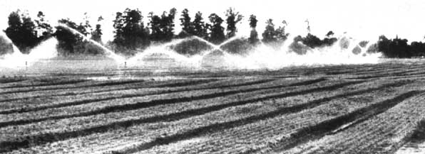
Some nurseries irrigate with rotary sprinkler heads instead of horizontal lines (Figure 4). Sprinkler heads are installed on individual risers spaced at approximately 40-foot intervals over the entire area (Figure 5). They are served by portable lines or permanently installed underground mains similar to those used in the horizontal-line system. The rotary head system has advantages and disadvantages similar to those of horizontal-line system, plus some additional as well. Some nurserymen claim that it interferes less with the use of machinery, because the risers spaced approximately 40 feet apart are supposedly easier to work among than horizontal line supports spaced about 52 by 12 feet. The system also has the advantage of permitting water to be applied at a faster rate than from a horizontal line. This may be of value when irrigating cover crops grown to maintain soil fertility.
FIGURE 4. - Rotary sprinkler system in operation. - Courtesy, Georgia Forestry Commission
FIGURE 5. - Detail of rotary sprinkler head and riser. - Courtesy, Forest Service, U.S.D.A.
Depending upon the particular model of rotary head, the drops of water will be large or small. If large, they can do devastating damage to newly germinated beds. Hence, heads that discharge only 5 to 7 gallons per minute at 40-pound pressure should be used. Later on, when the seedlings are large or when the area is in a cover crop for resoiling purposes, large heads with a greater discharge rate may be substituted if circumstances warrant such an expense.
The first cost of such a system can be reduced by using lightweight, quick-coupled pipe laid on the surface as laterals (Figure 6). These pipes have special slip-joint connections and are, therefore, readily disassembled and moved as required from place to place. They can be served from underground mains, or the cost of the system may he lessened even further by eliminating underground mains and using portable laterals all the way from the water source to the rotary head.
FIGURE 6. - Irrigation system with portable surface pipe. - Courtesy, South Dakota State Nursery
In addition to a reduction in installation cost, the portable system offers the advantage of allowing the risers to be removed from the area and thus give unobstructed space for tractors to plow and level the area after a crop is removed. A plan for a nursery rotary irrigation system and construction details for such a system are shown in Figures 7 and 8, respectively.
|
A. |
Gravel drive |
|
B. |
Center line of turn road |
|
C. |
14 sprinklers at 40 ft. = 520 ft. |
|
D. |
12 sprinklers at 40 ft. = 440 ft. |
|
A. |
Part circle sprinkler head |
|
B. |
Full circle sprinkler head |
|
C. |
Turn road |
|
D. |
As required |
|
E. |
Fin. grade |
|
F. |
1-in. galvanized pipe riser |
|
G. |
Valve box |
|
H. |
Screw end galvanized tee |
|
I. |
Reduced for reduction of pipe sizes as shown on layout |
Water screening. Rotary sprinklers will operate even though the water carries small particles of debris, but the water for horizontal sprinkler lines must be screened to prevent the nozzles from being plugged. A self-cleaning screen of the type shown in Figure 9 has operated satisfactorily for years at those nurseries where it has been installed.
FIGURE 9. - Plan for self-cleaning screen for piped water supply system. - Courtesy, Forest Service, U.S.D.A.
|
A. |
Battle wall |
|
B. |
Supports under wire |
|
C. |
Water flows over wall onto screen |
|
D. |
Wire cloth |
|
E. |
Dirt apron |
|
F. |
Dirt spills over |
|
G. |
Inlet |
|
H. |
Water level |
|
I. |
Cuts out for clean water overflow |
|
J. |
Clean water outlet pipe |
|
K. |
Stilling chamber |
|
L. |
Clean and open up |
|
M. |
Clean water chamber |
In its simplest form, this screening device consists of a concrete or wooden box covered with Fourdrinier wire. Fourdrinier wire is the flat-faced copper wire cloth, 60 mesh (3,600 holes per square inch), used in paper-making machines. For the water screen, it is placed smooth side up in the box at a slope of 15 to 20 degrees with suitable supports to prevent sagging. The mesh is so fine and the surface so smooth that foreign material rarely catches on it. The action of the water continually washes it clean so that it does not become clogged. Dirt and excess water pass over it and nothing but clean water passes through.
Incoming water enters through an inlet into the bottom of the stilling chamber at the back of the box. The clean water outlet is through a pipe line at the bottom of the front wall of the box. Operation of the screen is not affected by the amount of water entering the stilling chamber nor the amount of water passing out through the clean water outlet. It can be wide open or entirely closed. When the clean water outlet is closed, all water passes through the waste water outlet. Dirt and debris on the surface of the screen is continually washed down and over the water apron.
It is unwise to begin development work without first preparing a carefully conceived ground plan that establishes the location, direction, and dimensions of the beds; roads; windbarriers; pipelines; buildings; parking areas; and storage areas; present and proposed. An accurate survey of the site and preparation of a topographic base map is a must for such planning.
The utmost care should be taken when planning the locations and the directions of the beds to insure that radical changes will not be needed later to improve drainage, control erosion, or reduce operating costs. Such changes can result in exorbitant costs for relocating waterlines and other structures.
A combination of 4-foot-wide beds and 1½ or 2-foot paths is the general rule. Most standard machinery is well adapted to this combination, and most special machinery has been designed to fit it. Paths in which sprinkler lines are placed must be at least 4 feet wide to allow machinery to clear the sprinklers.
Within limits, the longer the beds the more efficiently they can be prepared, sown, sprayed, and lifted by machinery. If the horizonal type of irrigation system is selected, the length of the beds will depend upon the length of the line that an oscillator can turn. This is usually 400 to 500 feet if the water mains cross the ends of the beds and 800 to 1,000 feet if the mains cross the middle of the beds and pairs of oscillators are used.
Surface and subsurface drainage, erodibility of the soil, and economy of sprinkler-line construction usually determine the direction of the beds. On sites with both poor subsurface and surface drainage, the beds should run up and down whatever slope there is. On sloping ground, where surface drainage is ample and there is some tendency toward erosion, beds should parallel the contours as nearly as possible. Straight beds are preferable and they should be curved to follow the contours only in extreme cases. On a nearly level site with good subsoil drainage and no erosion, the beds may be run in whatever direction requires the least amount of pipe for sprinkler lines. Where drainage and other conditions permit, it may be well to run beds and sprinkler lines at right angles to the winds prevailing during germination or during the driest weeks of the summer. Such an arrangement insures optimum distribution of water from the sprinklers and minimum water loss from the beds.
Horizontal sprinkler lines ordinarily are set 50 to 56 feet apart. The 56-foot spacing provides space for nine 4-foot beds and eight 2-foot paths between each 2 lines, and a 4-foot path under each line. This arrangement permits the use of commercially available machines, such as a spray rig equipped with the standard 16-foot boom.
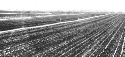
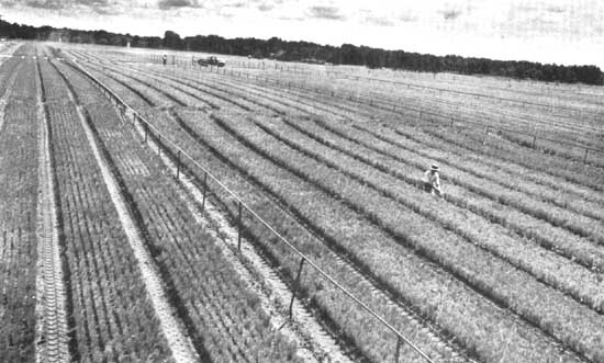
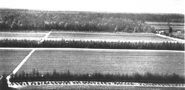
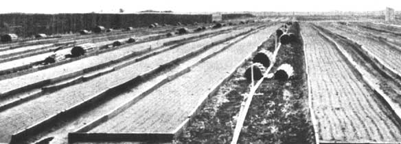
The beds are usually grouped into " blocks " of a size convenient from the standpoint of accessibility for trucks and movement of machinery. The nursery shown in the frontispiece is broken into areas of approximately 5 acres by crisscrossing roads. Other nurseries find 10 acres a convenient size.
If the nursery must be built on a hillside, terraces may be essential to erosion control. They must be expertly placed and built, and well maintained, or they may do more harm than good. Sprinkler lines and straight beds should parallel terraces as closely as possible. Some effective seedling area usually is lost where beds cross terraces, although properly shaped terraces seldom need hamper machine sowing, spraying, or lifting (Figure 10).
So far as slope, drainageways, and terraces permit, it pays to keep beds uniform in size. Beds of exactly equal size greatly simplify fertilizing, sowing, spraying, and machine operation, and they particularly simplify nursery inventory and cost accounting.
In regions of strong, drying winds, windbarriers around and within the nursery are essential if the area is 20 acres or more in size. Provision should be made for them in the nursery layout plan along with the roads, ditches, buildings, and other structures. As a general rule, belts of trees offer some protection for distances of 10 to 15 times their height. They should be located on the windward side of the nursery and parallel to the beds to give maximum protection and yet not interfere with nursery operations. In mechanized nurseries, long beds or rows are essential to efficient machinery operation. Hence, the rows or beds should not be interrupted by cross hedges or cross fences any oftener than is absolutely necessary.
Because newly planted windbarriers will not afford much protection, it may be desirable to retain strips of natural timber when clearing a nursery site (Figure 11). For example, strips 20 or 30 feet in width with a spacing of about 600 feet between strips might be preserved. Since such natural strips usually suffer considerable mortality from sudden exposure, breakage and uprooting, reinforcement planting may subsequently be necessary unless they are wide enough to withstand the loss of a few trees without reduction of effectiveness.
Some nurseries also use interior hedges of trimmed conifers at intervals of about 100 feet. Such hedges may suppress growth in adjoining seedbeds, but this effect can be reduced considerably by passing a knife-blade trencher, a plow, or a rolling coulter parallel to the hedge and several feet away from it at 3-year intervals.
Some nurseries use slat-wire snow fence in place of hedges. Nurseries with horizontal sprinkler lines find them to be a convenient support for such fencing.
An adequate road system, carefully laid out and well maintained, is essential to the efficient operation of a nursery. Major improvements such as warehouses, compost pits, and cone storage facilities must be accessible. Interior roads should be wide enough to provide turning space for tractor-drawn equipment. A 20-foot road width is a minimum for operating and turning most types of equipment, and 30 feet is recommended, particularly for large nurseries where mechanization of nursery operations is proposed.
An application of crushed rock or fine gravel ordinarily is desirable for main roads. The surfacing should be confined as nearly as possible to a 10- to 12-foot strip down the center of the road. Care should be taken to keep the surfacing material from spreading onto the production areas and becoming mixed with the nursery soil. This is particularly important if the surfacing material contains calcareous rock or fine materials that would lower the acidity of the soil.
Areas that have been in farm crops or pasture do not present so serious a problem as do those that must be cleared of brush, stumps, and tree growth. To maintain uniform fertility, the surface soil must not he disturbed more than is necessary; therefore, heavy equipment such as bulldozers should not be used for bunching trees and brush. Rather, the trees should be cut and the stumps pulled or removed by blasting. If possible, the slash and brush should be hauled from the area, rather than piled and burned in place.
The amount of leveling that is necessary will depend upon the topography and the nursery practices to be used, particularly the method of irrigation. Leveling should be avoided if possible and otherwise held to a minimum because moving the topsoil complicates the maintenance of a uniformly fertile nursery soil. When it is necessary to do a major job of leveling, the topsoil should be pushed aside and then spread back on the area after the subsoil has been excavated. This operation can be accomplished with a bulldozer, land plane, or road maintainer.
When the site has been cleared, a heavy plow especially designed for breaking new land should be used. This type of plow is sturdily constructed and stands up under use on land infested with roots, small stumps, and clumps of brush. After being plowed, the land should be disked with a heavy tandum disk to cut up the sod and hasten deterioration of the vegetable material.
Disking should be repeated and followed by harrowing with a spring-tooth harrow until the land is thoroughly tilled. Pieces of stumps, roots, limbs, and stones should be picked up and hauled off the area. Low areas, almost unnoticeable otherwise, often can be detected readily after heavy rains.
It is very important that the nursery soil be in good tilth and as free of weeds as possible for the production of conifer seedlings. Therefore, pasturelands or areas that have been in heavy sod for a long time preferably should be planted to a cultivated crop or kept fallow before being converted to nursery use.
A standardized list of equipment, universally applicable to the production of any given unit of trees, is not possible because conditions and requirements differ too much between nurseries. The operation of a nursery is essentially a farming operation; the common farm machinery, such as tractors, plows, harrows, and the like, are used to till the soil prior to planting the crop. For the specialized nursery operations of sowing, transplanting, root pruning, and lifting, special machines are required. Ordinarily they can be assembled from standard parts or modified from commercial machines in a local machine shop. Throughout various sections of this manual, descriptions are given of such specialized equipment. Some general instructions that are intended to aid in the selection of equipment follow.
In choosing a tractor, the nurseryman should consider the jobs and the character of the soil on which the tractor will be used. Pulling the tree lifter through the beds at a depth of 8 to 10 inches will probably be the heaviest job. Consequently, where only one tractor is available, it should be of a size adequate for that job. If the nursery is large enough to justify having two tractors, one large tractor and one small tractor is best.
The wheel-type tractor is preferred to the crawler type for general nursery work, because it is more maneuverable and less expensive to operate. One with 33- to 35-drawbar horsepower is satisfactory for heavy work, such as plowing, disking, or pulling the tree lifter; for light work, such as drawing a utility trailer, mechanical seeder, or fertilizer spreader, 15- to 18-drawbar horsepower is adequate.
A sturdily constructed plow and disk harrow usually are required for breaking new ground or plowing old fields that have brush or a heavy sod. Following initial ground preparation, a 16-inch, 2-bottom plow, or a 26-inch disk plow with disks 10 to 12 inches apart, is a very effective tool for turning under soil-improvement crops and doing general tillage work. Disk plows and chisels are favored by some as a safeguard against formation of a plow sole.
Where dead furrows are a hindrance in maintaining a level seedbed, a two-way plow is useful. It is fitted with both a right- and left-hand bottom, and, when plowing back and forth across the field, it throws all the furrows one way.
A spike-tooth harrow aids materially in breaking clods and can be used effectively for leveling the ground. Various depths of penetration can be obtained by adjusting the angle of the spikes. The width of cut varies with the size of the single section and the number of sections hooked together and pulled abreast as a unit.
The spring-tooth harrow is useful for shallow cultivation in the final preparation of seedbeds. It can also be used to dig out persistant grass rhizomes and noxious weeds, and to rake debris to the surface. Depth of penetration is governed by changing the pressure on the teeth. This tool is made in sections, and the width of cut is governed by the number of sections assembled as a unit.
After being cleared or cultivated, the land usually can be leveled with a " float " drawn across the field at right angles to the direction traveled earlier by the harrow. The nurseryman can build a " float " by lapping four or five 10- or 12-inch planks (8 to 10 feet long), securely fastening them together with bolts or spikes, and bracing them across the top to give the unit rigidity. Short lengths of chain fastened 24 to 30 inches from the ends of the front plank will serve as a hitch. Extra weight or pressure can be obtained by using stones or sandbags as ballast. (See also the smoothing disk harrow pictured in Figure 15, page 27).
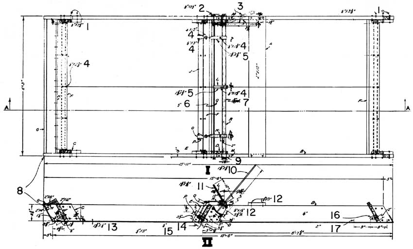
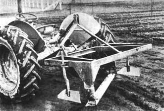
A " land plane " as described in Figure 12 is useful for moving soil into hollows 4 or 5 inches deep and several yards across.
FIGURE 12. - Construction details for Bessey land plane. - Courtesy, Forest Service, U.S.D.A.
|
I |
Plan |
|
II |
Cross-section A-A |
|
1. |
Carriage bolts |
|
2. |
Bolts through ratchet |
|
3. |
Dotted lines indicate side thrust Of ratchet lever |
|
4. |
Bolts |
|
5. |
Strap iron |
|
6. |
Tie rod |
|
7. |
Iron pipe |
|
8. |
¾ in. hole at each end for cable connection |
|
9. |
Washer and cotter pin at each end |
|
10. |
Strap iron lever |
|
11. |
Strap iron handle |
|
12. |
Lag screws |
|
13. |
Strap iron runners |
|
14. |
¼ in. steel plate |
|
15. |
¼ × 3 in. bolts with countersunk head |
|
16. |
¼ in. iron plate bolted to crosspiece and sides |
|
17. |
2 in. screws spaced 9 in. apart full length of runner |
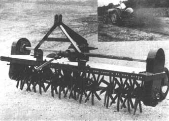
The rotary tiller is a new tool that in effect plows, disks, and harrows in one operation (Figure 13). It has proved satisfactory for preparing ground and working compost and green cover crops into the soil. Also, this tiller is ideal for preparing a very loose, friable seedbed in light sandy soils. However, it has the disadvantage of destroying crumb structure and so making the soil more than normally subject to wind erosion. Experience in some nurseries indicates that the rotary tiller is effective in destroying some insect larvae, such as white grubs, which infest the soil and feed on the roots of seedlings.
FIGURE 13. - Rotary tiller. - Courtesy, Agricultural Engineering Research Division, U.S.D.A.
This tool has a high-speed rotor equipped with tines that pulverize and thoroughly mix the soil. The very small models are compact, self-propelled units, and the larger ones, which vary from 3 to 6 feet in width, operate from a power takeoff or are powered by an engine mounted on the forward part of the machine. The power is transmitted by a double universal joint and spiral bevel gear to the rotor assembly. A hood mounted over the rotor confines the pulverized soil to the area being tilled. Depth of tillage is accurately controlled by adjustments provided by the rotor lifting bar.
The ordinary farm grain drill can be used in a nursery to advantage for seeding cover and green manure crops. These machines are adaptable to sowing grain, grass, and legume seeds, and can be adjusted to sow at desired rates per acre. Since slightly better results can be obtained if the seed is firmly packed, drills equipped with packing attachments are recommended for use in sandy soils. Experience has shown that an 8-foot drill is better adapted to nursery requirements than either a wider or narrower drill. Grain drills can be obtained with attachments for fertilizing the crop at the time of drilling the seed.
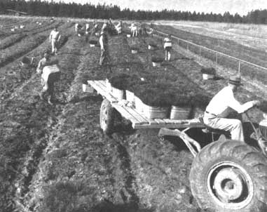
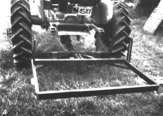
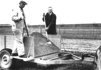
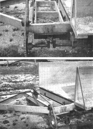
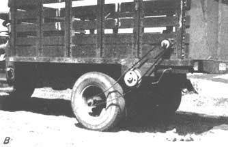
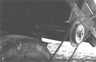
Two-wheeled trailers with a gauge sufficient for them to straddle the beds are invaluable when placing shade, handling mulch, or doing other jobs directly upon the beds. The type shown in Figure 14 is an example of such a trailer. There is no standard design, because they are usually made at the nursery from worn out truck or auto chassis.
FIGURE 14. - Home-made flatbed trailer. - Courtesy, Forest Service, U.S.D.A.
In large nurseries much or all bed making and finishing is done with regular agricultural machinery and special bed-shaping equipment, usually tractor drawn. Handwork is limited to odd corners, to places where beds cross terraces, and to occasional final smoothing or freshening of the bed surface.
The beds must be worked when the soil is neither too dry nor too wet, especially the latter. If too dry, it is hard to break up clods or reach the proper depth. If too wet, puddling and clodding may result with consequent injury to the crop and an increase in the cost of later cultivation and weeding.
Plowing must be deep, at least 8 or 9 inches, to permit good development of seedling roots. Harrowing must be deep and thorough for the same reason, and to provide good conditions for seed germination. The most suitable implements depend largely on the soil, and usually can be determined by noting which types work best on similar sods nearby. A type that does a thorough job of breaking clods and leaving a smooth surface is shown in Figure 15.
FIGURE 15. - Clod breaker and smother. - Courtesy, Larchmont Engineering Company
Beds should be free from any coarse organic material likely to make the surfaces uneven or to prevent good establishment of seedlings. Winter cover crops of moderate volume must be turned under 4 to 6 weeks before final bed preparation; heavy crops, considerably earlier. Only well-decomposed or finely divided compost or other organic matter may be applied safely just before the beds are made up.
Sparse or moderate crops of annual weeds should be destroyed by plowing or harrowing a little in advance of bed making. Abundant or carryover weed crops may require repeated working during a considerable period in advance of sowing.
Heavy soils, heavy subsoils with poor subsoil drainage and very level sites with poor surface drainage all call for beds raised above the nursery paths. Usual elevations are 3 to 4 inches, but in extreme cases beds are built up 6 inches or more above the paths. On soils that erode easily, or on very sandy or otherwise dry sites, beds should be kept low. Local observation and experience are the best guides to the optimum elevation which may differ from place to place in the nursery.
Theoretically, the surface of the bed should be flat on ideal soils, slightly rounded on the less wen-drained soils, and slightly troughed on droughty soils. However, rounded beds have, shown little practical superiority, and in most mechanized nurseries bed surfaces are made flat regardless of soil.
Some nurseries require sideboards above the ground to reduce wind or rain erosion and to support protective screens (Figure 16). The boards are put in place after the area is prepared but before sowing. Such boards may be rough, low-quality lumber, but should be of some rot-resistant species. If such boards are creosoted to reduce deterioration, they should be weathered for at least a year before use because the creosote might leach out and kill seedlings. The boards can be supported in any convenient manner. Several models of such supports are shown in Figure 17. Some nurseries that use great quantities of sideboards find it more economical, because of high labor costs, to use iron supports of one design or another (Figure 18).
FIGURE 17. - Various types of sideboard supports. - Courtesy, Forest Service, U.S.D.A.
|
A. |
Width to fit side board material used |
|
B. |
Strap iron |
|
C. |
Length appropriate to texture of soil |
|
D. |
Iron bar |
|
E. |
Weld bar to strap iron |
FIGURE 18. - Seedbed sideboards with supporting pegs of iron. - Courtesy, Forest Service, U.S.D.A.
The use of sideboards to support the sides of raised beds should be avoided if at all possible, because their original cost, the cost of installation and removal, and their deterioration during use can be extremely expensive in a large-scale operation. Today almost universal practice is to add an unsown shoulder on each side of the bed. Three-inch shoulders are wide enough on most soils, but 6 inches may be needed where beds are high above the path and the soil erodes easily. Since the shoulders are on the same level as the beds, they offer no obstruction to mechanical seeders. The unsown shoulders gradually wash or are trampled down into the paths, until by lifting time the beds are reduced almost exactly to 4 feet and the paths widened to a full 2 feet. This assumes, of course, that the nursery uses 4-foot beds on 6-foot centers.
At large nurseries, beds are shaped by attachments to farm tractors, or by special bed shapers. The best of these devices space beds accurately with no guides except stakes at each end. The bed former in Figure 19 has two disks that churn up the soil and throw it toward the center. They may be raised or lowered, and turned at any angle required to handle a particular soil condition. Behind the disks are two angled leveling boards that work the soil toward the center where a third leveling board, as wide as the frame, completes the shaping operation. Two rows of small disks follow to smooth and pulverize the soil. This machine is designed to operate from a tractor that has a 3-point hydraulic tool-bar hitch. Modifications of it, made locally, are in use at many nurseries.
FIGURE 19. - Nursery bed former. - Courtesy, Larchmont Engineering Company.
In some soils it may be desirable to let the beds settle before sowing. Hand-shaped beds are sometimes settled by allowing rain to fall on them a few times and then releveling and freshening the surface just before sowing. Generally it is quicker and equally effective to roll the beds before or after sowing, or both, with 300- to 400-pound metal or wooden rollers, preferably 4 or 5 feet in diameter. Where tractor-drawn bed shapers and mechanical seeders are used, the weight of the bed shaper partly settles the beds, and the rollers in the mechanical seeder complete the process. With such equipment, settling by rain or special rolling is unnecessary.
Final pulverizing of the seedbed surface can be done either by the mechanical bed shaper or with hand rakes. Surfaces that have dried in the sun or become crusted by rain are freshened by dragging or by hand raking immediately before sowing to permit rolling the seed into at least moderately moist soil.
Hand sowing
Uniform hand sowing of seed is quite possible, but such sowing is time-consuming and requires considerable care. As an aid in obtaining this uniformity, each bed and the seed for it should be divided into equal parts, and each subdivision sown with about three fourths of the seed allotted to it, after which the readily apparent thinly sown parts can be touched up with the remaining one fourth.
Hand sowing, either in drills running crosswise of the bed, or broadcast, remains preferable to machine sowing in very small nurseries and in certain test plots in large ones. Crosswise drills, usually sown 6 inches apart, are easier to hand weed than drills running lengthwise, especially in 5-foot beds.
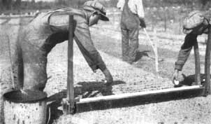
The " Bateman " seed trough (Figure 20), which is opened to drop seed, closed again, and moved along the bed by tall handles, is a most effective device for sowing crosswise drills by hand. Two men with suitable measures cut from some box or tin can scatter seed in their respective halves of this trough. They can drill sow about 100 linear feet of either 4-foot or 5-foot wide bed per hour.
FIGURE 20. - Seeding with a Bateman seed trough. - Courtesy, Forest Service, U.S.D.A.
Machine sowing
It is important that uniform stands of seedlings or cover crops be obtained. Although seeding by hand can be done quite successfully by trained and experienced help, it cannot be done with the uniformity and speed that is obtainable with mechanical seeders.
With a machine, seedbeds may be sown either in drills running lengthwise of the beds, or broadcast. Drills are essential if the seedlings are to be side-dressed with dry fertilizer or cultivated during the growing season. Some nurserymen feel that seedlings in drills can be lifted with less root injury from stiff soils than those in broadcast beds. With present-day methods, however, especially those of weeding by use of chemical sprays, broadcast beds cost no more than drill-sown beds to sow or weed, and they seem likely to replace the latter in many nurseries. Broadcast sowing reduces some diseases - for example, sand-plash damping-off of longleaf pine - and theoretically permits better development of seedlings than does drill sowing.
At nurseries where the seed is sown in drills, a spacing of 6 inches center to center is commonly used. On a 4-foot bed, this arrangement permits eight drills between the two protective shoulders. To leave maximum clearance for cultivator and fertilizer attachments, the drills should be as narrow as the nurseryman believes appropriate for the species being planted. To gain such added width between drills, some nurserymen sow only six or seven drills on a four-foot bed, but increase the number of seedlings per foot of drill. Six drills is about the minimum without seriously overcrowding the seedlings in each drill or reducing the number of seedlings per bed.
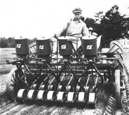
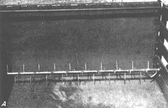
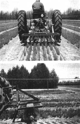
The unit in Figure 21 is operated from a tractor that has a threepoint hydraulic tool-bar hitch. Each seeder unit is mounted separately to permit individual movement over holes or obstacles without affecting the other units. All units are adjustable laterally to any row width or number of seeders desired to a maximum of eight, as shown. This machine can be changed from a drill to a broadcast seeder by removing the parts below the ends of the flexible tubes and substituting a splashboard on which the seed strike as they fall to the ground.
FIGURE 21. - Tree seed sowing machine. - Courtesy, Forest Service, U.S.D.A.
A few models of tree seed sowing machines are commercially available. There are also a number of all-purpose agricultural and garden seeding machines that can be used with little or no modification for sowing geed of many species of trees.
Some nurserymen prefer to build their own machine and combine such features as a roller and a sand spreader with the seeder. The seed cups and seed tubes that convey the seed from the hopper to the seeding assembly can be selected from the many models of commercial farm seed-drill parts. The seeding assembly parts, including an adjustable furrow-opening shoe, a furrow coverer, and a packing wheel mounted on a frame, can be taken from commercial hand-pulled seeders. A clever man, aided by a seeding machine parts catalogue, can assemble a completely satisfactory machine if he cannot or does not wish to buy a commercial model.
Machines can be designed to sow seeds of various conifers at different densities. For the larger seed, the rate of sowing is regulated by a change of gear ratios and a change in the size of the seed cup opening in the bottom of the hopper. For the very fine seed, seed cup reducers are inserted. A mechanical drill seeder can also be used for a few of the broadleaf species, such as mountain ash, yellow birch, and black locust. Maple and ash seed, whose wings are difficult to remove, and acorns and nuts, can best be seeded by hand in small open furrows.
A broadcast seeder of simple design and completely satisfactory for many species of conifer seed has been devised at the New Hampshire State Nursery. A commercially available special fertilizer spreader and seeder is combined with a roller on a simple iron frame suspended from a tractor 3-point hydraulic tool-bar hitch (Figure 22). The seed, broadcast on a loose seedbed surface and in a sandy soil, will be covered sufficiently by action of the roller following the seeder. According to soil texture and moisture content, the weight of the roller can be varied by partly filling it with water to obtain the degree of covering action required,
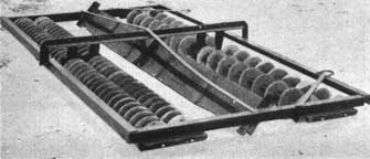
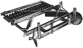
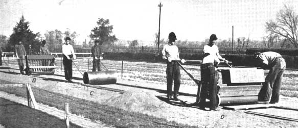
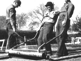
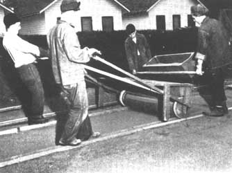
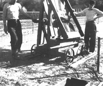
If only a few hundred linear feet of seedbeds are required, hand-drawn equipment to shape the beds and place and cover the seed may be more practical than tractor-drawn machines. Figures 23 through 28 show the machines that served this purpose well for many years prior to mechanization at a United States Forest Service nursery in Nebraska. The nursery has an annual capacity of several million trees. The seedbed tracks were 2- by 4-inch strips of wood laid end to end and fastened to the ground with inverted U irons driven through holes in their ends. A shaper on flanged wheels was pulled over the tracks (Figure 24) when it was necessary to smooth the surface prior to sowing the seed by hand or machine. After seed sowing, a light roller (Figure 23, C.) was pulled over the bed to press the seed into the soil, and then the bed was covered with sifted soil from a sand spreader (Figure 25). Trials should be made to determine whether rolling is necessary, because some nurseries find it possible to omit this step; others use the roller and then omit the covering; still others must both roll the seed and apply the covering.
|
A. |
Surface shaper. |
|
B. |
Seeder. |
|
C. |
Roller. |
|
D. |
Sand spreader. |
FIGURE 25. - Manually operated sand spreader. - Courtesy, Forest Service, U.S.D.A.
|
I |
Roller |
|
II |
Wheel |
|
III |
Sand carrier |
|
A. |
Side view |
|
B. |
End view |
|
C. |
Inside view |
|
D. |
Top plan |
|
E. |
¼-in. by 1¼ in. steel fins set into roller body |
|
F. |
1-in. diam. shaft |
|
G. |
Ratchet nailed to end of roller |
|
H. |
Screen door spring to keep pawls in place |
|
I. |
1-in. hole |
|
J. |
½ × 3 ½-in. bolt |
|
K. |
Position of ratchet |
|
L. |
¼-in. brace rods |
|
M. |
½-in. carriage bolts |
|
N. |
Lag screws |
|
O. |
2-in. rubber strip |
|
P. |
1-in. leather strip |
FIGURE 28. - Construction detail for sand screen (side view). Courtesy, Forest Service, U.S.D.A.
|
A. |
Carriage bolt |
|
B. |
Cross brace |
|
C. |
Handle |
|
D. |
Cleat |
|
E. |
Cleat at joints |
|
F. |
Platform for sand box |
|
G. |
¾-in. galvanized iron pipe axle |
Seed covering with soil or sawdust
Covering seed with soil is a practice that cannot be prescribed for all nurseries. Some do nothing more than press the seed into the bed surface without further covering; others apply the covering as a part of the seed-sowing job by equipping the seeding machine with rollers and scrapers under the seed tubes to cover the seed with seedbed soil. At the other extreme are nurseries that apply ¼ inch or more of sand, or sifted soil, or sawdust, or a mixture of these, on top of the .seed, either from a hopper built on the seeding machine or from a separate sander that follows behind. Only tests will determine what is right for a specific nursery.
A sifter built on a trailer to pull behind a tractor has been developed at the State nursery in Lansing, Michigan, to apply a covering of sand or sawdust. It consists of a tractor-trailer with a box to carry a quantity of the covering material. In front of this box a sifter is suspended between cross members in the trailer frame by four pieces of strap iron 8-inches long. The sifter frame is made of 1½-inch angle iron 14 inches wide and 4 feet long. Inside the frame, resting on the angle iron is a removable sifter made of a sheet of hardware cloth fastened to a wooden frame. The sifter is filled by two men who ride on the trailer and scrape the sawdust or sand into it (Figure 29). Since the sifter lies loose on the angle iron, it may be lifted out and cleaned.
This nursery has three wood-frame sifters with different size mesh hardware cloth - ¼ inch for sand, 3/8 and ½ inch for sawdust. By adjusting the screen and the speed of the tractor to the material to be sifted, the desired thickness of cover can easily be obtained.
A shaft with two universal joints transmits the power from the power take-off of the tractor to the sifter (Figure 30). This makes it possible to turn at a sharp angle to enter the seedbeds without disconnecting the drive shaft. The universal shaft connects to a short rigid shaft 2 feet 6 inches long mounted on the front of the trailer frame. A Velos V-belt transmits power from the shaft to a pulley on the end of a crankshaft. (A Velos belt can be used without a tightener, because links can be removed from or added to it.) The crankshaft and piston rod used to oscillate the sifter were salvaged from a one-cylinder gasoline engine.
The speed of the sifter in relation to that of the power take-off can be regulated by the size of the pulleys used. At this nursery, a 4-inch pulley on the sifter shaft and an 8-inch pulley on the crankshaft is satisfactory.
See also the manually operated sand spreader shown in Figures 25 and 26 and the truck type shown in Figures 32 and 33.
Seedbed covering with cloth or mulch
In many areas, beds are covered to protect seed from birds and from displacement by rain, and particularly to keep seed and soil continuously moist. The latter is true, even though a sprinkler system exists to supply water. The covering must let water and presumably some light reach the seed. It must be nontoxic, inexpensive, quick and easy to apply, and, if need be, easy to remove. A cover that does not meet these specifications may seriously reduce or completely destroy the seedling stand.
Examples of materials used for this purpose are burlap or other coarse cloth; pine needles, commonly called " pine straw "; or wood chips. Both cloth and pine straw have proved superior to grain straw, paper, sawdust, soil, and sand at some nurseries, but not at all.
Pine straw usually requires more labor than cloth to apply and remove, gives less protection against birds, floats away if rain floods the beds, and is a potential source of needle infection. However, it requires no wire pins, prevents rain packing the soil, and can be obtained in quantity by nurseries within forest areas. Seedlings of all species come up through a properly applied layer of pine straw. If too thin or too thick a layer is applied, the thickness can be adjusted even while germination is taking place. Seedlings are less seriously flattened and less rapidly smothered by pine straw than by cloth. Therefore, removal of pine straw need not be timed as precisely as the removal of a cloth-a feature especially advantageous with seed that germinate slowly and irregularly. In nurseries subject to excessive heat, drought, or wind erosion, part of the straw may be left in place all summer as a mulch. This practice has materially improved the quality of nursery stock in some instances.
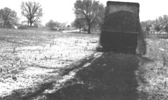
Pine straw can be scattered evenly over the beds by hand or with forks, but at large nurseries a commercially available manure spreader modified to prevent sidewise scattering is best. The correct depth is ½ to 1 inch before settling and less than ½ inch after settling-just enough to conceal the seed. The pine straw required for a 4- by 400-foot bed is between 2½ and 5 cubic yards. An acre of 4-foot beds with 2-foot paths requires 45 to 90 cubic yards of straw. The fewer twigs and cones the pine straw contains, the easier it is to spread. Storing the straw in piles for a year before use rots it somewhat and facilitates uniform distribution with a manure spreader. A simple method of unloading the straw or other mulch is shown in Figure 31.
FIGURE 31. - A method for unloading pine straw mulch from vehicle. - Courtesy, Forest Service, U.S.D.A.
|
A. |
Rope placement while loading |
|
B. |
Rope laid out on empty truck bed |
|
C. |
Attach rope, to stake socket |
|
D. |
Pine straw |
|
E. |
Rope |
|
F. |
Tractor |
|
G. |
Pull |
Some nurseries use sawdust, wood chips, or similar small flaky organic matter as a mulch and also as a soil amendment to help maintain fertility. It is most laborious to distribute this material uniformly if it must be shovelled directly from the truck or spread from piles in which it has been dumped. Equipment to be attached to the tail gate of a dump truck has been developed by the Georgia Forestry Commission and has performed satisfactorily at its nurseries (Figures 32 and 33).
FIGURE 32. - Self-unloading truck spreading sawdust. - Courtesy, Georgia Forestry Commission
FIGURE 33. - A. Agitator mechanism on self-unloading truck. - Courtesy, Georgia Forestry Commission
FIGURE 33. - B. Side view of drive mechanism and a close-up. - Courtesy, Georgia Forestry Commission
FIGURE 33. - C. Side view of drive mechanism and a close-up. - Courtesy, Georgia Forestry Commission
If this device is to be used to spread mulch directly onto the surface of seedbeds, a horizontal screen cylinder rotating beneath the falling material should be added. The cylinder should be as long as the width of the truck body and about 10 inches in diameter. It should be made of ¼- to ½-inch mesh hardware cloth on a horizontal axle supported by brackets fastened to the truck's frame. An additional gear and chain added to the drive mechanism on the wheel (Figure 33) causes the cylinder to rotate as the mulch falls over and through it. This results in a reasonably smooth, even distribution of the mulch.
Cloth covers can be laid and removed more quickly than pine straw. During germination, they give better protection against birds and flooding rains. Their chief disadvantages are high initial cost of cloth and pins, the necessity of timing their removal exactly, the tendency of certain soils to pack hard under cloth, and deterioration of the cloth. Also, the seedlings are especially susceptible to damage by hail and heavy rain during the first 2 or 3 weeks after the cloth is removed.
The two favorite cloth covers are jute burlap and Osnaburg or similar rather porous cotton cloth. Burlap weighing 9 or 10 ounces per square yard is preferred; 12-ounce burlap is a little too thick and unnecessarily expensive, while 7- or 8-ounce burlap is a trifle light, especially after a season's use. Nine-ounce burlap with 11 to 13 threads per inch of warp and 10 to 12 per inch of filling is preferred. New burlap may be purchased in 100-yard rolls, in any desired width. For 48-inch beds, the 54-inch width should be obtained. Secondhand bags stiched together into strips are sometimes available at less cost, but they have the disadvantages of variations in weight and durability, seams that hinder laying and disturb the seed when the cover is removed, and frequently holes that expose the seed.
Cloth covers may be laid by land or by mechanical layers pulled behind the seeder. At some nurseries, a reel is mounted on top of the seeding machine in such a manner that the cloth unrolls from the reel and passes under the seeder's roller as the work progresses. Thus, the cloth is immediately pressed into place on top of the seed. This makes it possible to sow even when the beds are so moist that soil and seed would otherwise stick on the roller.
After laying, the cloth must be stretched and fastened down with pins stuck through the edges and into the ground. Such pins are usually made of a stiff galvanized wire and have a loop bent into one end. To facilitate handling, the loop should be of a diameter somewhat larger than a workman's finger. Placed at Moot intervals to keep the wind from flapping the cloth and injuring the seedlings, such pins for a 4- by 400-foot bed require about 350 feet of wire. Pins for an acre of 4-foot beds with 2-foot paths require about 6,000 feet of wire.
Seeding, burlap placing and pinning can be done as a combined operation by two men working from a low trailer pulled behind the machine. On large-scale operations, the cost of making such equipment is well justified. Such equipment is not commercially available - it must be made in local shops. The design shown in Figure 34 has proved satisfactory.
FIGURE 34. - The burlap pinner trailer. All connections are welded. - Courtesy, Forest Service, U.S.D.A.
|
A. |
2¼ in. strap iron |
|
B. |
Pin sticks, ¾ in. pipe, 1 in. flat washer, welded to bottom to support stick in position - length 18 in. |
|
C. |
Burlap layer frame |
|
D. |
Seat bolted to seat support |
|
E. |
2½ × 5/16 in. brace |
|
F. |
Foot support |
|
G. |
Pneumatic tire (wheelbarrow type) |
|
H. |
Spring steel |
|
I. |
Swivel |
Cloth covers must be removed before an appreciable percentage of the first seedlings have been smothered or have worked their way through the fabric, but not until most of the seed have germinated. A rough practical rule is to take off cloth covers when seedbed germination equals two-thirds to three-fourths of laboratory germination. Great care, as well as correct timing of removal, is necessary to avoid destruction of seedlings just taking root. Failure to clean and store cloth covers properly may necessitate buying a complete new supply each year. The cloth should be cleaned by washing - laying it on the grass in the rain is common practice or beating, and it must then be thoroughly dried. Storage of damp cloth can lead to fire from spontaneous combustion. A tractor-powered device to facilitate brushing and rolling the burlap after drying is shown in Figure 35.
FIGURE 35. - Power-driven burlap roller. - Courtesy, Forest Service, U.S.D.A.
|
1. |
4 × 4 in. support for brush, 9 in. base, 2 in. top |
|
2. |
Wood roller support (2 × 6 × 28½ in.) fitted into top of support |
|
3. |
2-in. pipe with collar on inside end, large end of hall of split roller bolted to pipe: outside end is reduced to a 1-in. pipe 6 in. long to form a handle |
|
4. |
Upper bearing hall-hinged to permit removal of roller |
|
5. |
Roller - hardwood 66 in. long, ¾ in. diam. split on diagonal for ease in removal from completed burlap roll |
|
6. |
Frame, 4 × 4 × 60 in. |
|
7. |
Brace, 1½ × 7 in. |
|
8. |
2-in. pipe with collar on inside end: large end Of second half of split roller is bolted to pipe, a 2- to 1-in. reducer is fastened to outside end of pipe with 1-in. square shaft 3½ in. long welded into the 1-in. end of reducer |
|
9. |
Hollow shaft 1½-in. square, 3 in. long, for detachable connector between roller and sprocket shaft |
|
10. |
Pillow block bearing, 4 in. long for ¾ in. shaft |
|
11. |
Sprocket, cast iron, 9 in. diam., 26 teeth fastened to ¾ in. shaft |
|
12. |
Slotted support for brush, 1/8 × 4 × 10 in. with 3/8-in. slot |
|
13. |
Roller, 1¼ in. pipe, 55 in. long running on ¾ in. pipe shaft, 58 in. long |
|
14. |
Brush, 59 in. long, bristles up |
|
15. |
Brush, 53 in. long, bristles down |
|
16. |
Slotted support for roller (1/8 × 6 × 13 in.) with 15/16-in. slot |
|
17. |
Spring, 3 in. diam., 8½ in. long, to provide tension to brush |
|
18. |
Brace ½ in. bolt 51/8 in. long |
|
19. |
Brace, flat iron (3/8 × 1½ × 36 in.) welded at top, bolted to trailer frame at bottom |
|
20. |
Steel shaft, ¾ in. diam. with 1-in. pipe, 3 in. long, for bearing fastened to brackets by U-bolts of ¼-in. diam. |
|
21. |
Sprocket steel, 3 in. diam. 11 teeth, fastened to ¾-in. sprocket |
|
22. |
Steel brackets to support bearing for shaft |
|
23. |
¼-in. steel plate fastened to trailer tongue by 2 U-bolts of 5/8 in. diam. |
|
24. |
Drive shaft, 1 in. hollow square, female |
|
25. |
Drive shaft, 15/16 in. square, male |
|
26. |
Universal joint |
|
27. |
Flat iron bracket (½ × 4 in.) bent at right angle to support shaft bearing |
|
28. |
Brace, T-iron 3/8 × 1½ in. welded at both ends |
|
29. |
Chain, detachable sprocket, 82 links. |
|
30. |
Wood block (3¼ × 4 × 1 in.) |
Untreated cloth has a short life - perhaps not more than a single season. Cloth treated to resist deterioration is commercially available, or such treatment can be given at the nursery by impregnating it with a solution of certain copper salts. A formula found satisfactory at many nurseries is as follows:
|
|
Pounds |
Percent by weight |
|
8.0 percent copper naphthenate solution |
9.7 |
8.3 |
|
Alkyd resin, clear, or its equivalent |
15.4 |
13.3 |
|
Mineral spirits (white spirits of petroleum) |
31.6 (5 gal.) |
27.1 |
|
Chrome green (Cr2O3) - dry powder form rather than ground in oil |
1.5 |
1.3 |
|
Water |
58.0 (6.95 gal.) |
50.0 |
|
TOTAL |
116.2 |
100.0 |
The 8.0 percent copper naphthenate solution is commercially available. Solutions of other strengths are on the market. The formula above applies only to the 8.0 percent solution; if a weaker solution is used, the amount of solution must be increased and the amount of water must be decreased to give the same amount of metallic copper. Chrome green may be obtained from paint companies. It is much easier to formulate in powdered form than when ground in oil; the quantity given in the formula is for the powdered form.
The above formula is recommended because both straight copper napthenate and burlap are light-sensitive. Addition of chrome green as a pigment prevents appreciable loss of metallic copper and also deterioration of burlap fiber. The alkyd resin serves both as an emulsifier and as a binder to keep the pigment in the fiber.
To prepare the solution, first dissolve the 8.0 percent copper napthenate in the mineral spirits. This is most easily done by setting the container of spirits in hot water (130° F.), but is possible even at a lower temperature if time enough is allowed and the mixture is stirred with a paddle. CAUTION: Do not use an open flame for this purpose.
Next, when the copper naphthenate has been completely dissolved, add the alkyd resin and mix thoroughly by constant high-speed agitation. Such mixing can be accomplished in the tank of a power sprayer, which has an agitator. Temperature may be disregarded. Third, add the specified amount of water, still maintaining constant high-speed agitation. Lastly, add the pigment, gradually, still maintaining constant high-speed agitation.
A 0.5 percent copper content, by weight, is desired in the treated burlap. This is obtained by thoroughly wetting the burlap with the prepared solution, then passing the treated cloth flat between two rollers to remove the surplus. For combined effectiveness and economy, the take-up after wetting and wringing should be 75 percent of the dry weight of burlap. The burlap must then be dried thoroughly before storage or use. It should be flat during drying to prevent movement of solution within the cloth with resultant unevenness and ineffectiveness of treatment.
Treated burlap should be weathered for 3 months or more before using it on seedbeds, because germination under freshly treated burlap is 10 to 30 percent lower than under untreated burlap. The newly treated burlap may be given the requisite weathering by exposing it to sunlight and rain, but not in contact with the ground. However, second-year trials with weathered burlap indicate no adverse effects resulting from the copper naphthenate treatment. This treatment has cost about 5 cents a yard at some nurseries. Treated burlap lasts five to ten times as long as untreated.
Polyethylene covers
Covering the seedbeds with polyethylene sheets creates a greenhouse effect that is desirable for certain species. For example, the problem of long-delayed and erratic germination of Juniperus seed at Oklahoma State nurseries was solved by the use of such sheets. The technique was as follows:
Clean, dry, untreated juniper seed was sown in early fall on conventional seedbeds. A light covering 1/8- to ¼-inch thick of sawdust was then spread over the seedbed, after which it was thoroughly watered and then covered with a polyethylene sheet. The polyethylene used was clear, 53 inches wide to cover adequately a 48-inch bed, and 2 millimeters in thickness, weighing I pound per 100 square feet. Burlap was laid over the polyethylene to help hold it in place against wind damage. No irrigation was needed while the polyethylene was in place, because it condensed water vapor that would otherwise have been lost, and returned it to the soil. The covering was removed when germination was nearly completed on March 15.
Some species in some localities benefit if partially shaded during certain stages of their development. Experimentation is needed to establish the desirability of this practice at any specific nursery.
Wooden slats nailed to light frames of a size convenient for two men to handle are frequently used for this purpose, but an easier method is to use slat-wire snow fence supported by two or three parallel wires running the length of the bed. The wires are held at the desired distance above the surface by vertical stakes of wood or iron (Figure 36).
FIGURE 36. - Roll-type snow fence to shade seedbeds. - Courtesy, Forest Service, U.S.D.A.
|
A. |
9-gage galvanized iron wire |
|
B. |
Rolled lath space |
|
C. |
Crossbars (1 × 2 × 48 in.) |
|
D. |
Stakes |
There is now also commercially available a material woven of coarse plastic threads in various patterns of stripes or checks to yield a predetermined degree of shading. Such material has many advantages, such as ease of handling, less weight, and less bulk in storage over the slat type of shade in rolls or rigid panels.
Such shade is an obstruction and must be removed when it is time to weed and spray the beds. Its placement, and handling during the season is an annual expense additional to its original purchase price. It is, therefore, desirable to avoid its use unless the advantages outweight the extra costs involved.
Under favorable circumstances, the root pruning of conifer seedlings in the beds may cause them to develop into a better balanced plant with a more fibrous, compact root system and a smaller top. In some cases, the improvement is sufficient to eliminate the need for transplanting. The best results in such cases have come from root pruning at a depth of 3 to 5 inches in the spring of the second year.
Several of the lifters used as an aid in digging trees will serve also as horizontal root pruners. The nursery of the Industrial Forestry Association at Nisqually, Washington, developed a special pruner with an oblique blade that is even better for this purpose than a lifter is (Figure 37).
FIGURE 37. - Nisqually oblique blade root pruner. - Courtesy, Industrial Forestry Association
Immediately after root pruning, the beds should be watered thoroughly to make the soil settle back into place and reduce wilting of the trees. Root-pruned conifer stock may suffer from a nutritional deficiency, because of the loss of a 50 percent more or less of its root system. Application of a complete liquid fertilizer, totaling about 300 pounds per acre of 15-30-15 fertilizer or its approximate equivalent, within a week or two of root pruning will aid in maintaining normal, healthy foliage color and obtaining improved field survival.
Vertical pruning is also desirable in many cases (Figure 38). It should especially be performed along the edges of each bed, because the trees there tend to develop rather wide-spreading lateral roots extending into the paths.
For stock grown in drills, vertical pruning can best be done with sharp, rolling colters mounted on an axle and located at midpoint between rows. The rolling colter is less likely to clog with refuse and tree roots than vertical individual knives, even when these are slanted downward and backward.
Top pruning to eliminate unwanted top growth is also successfully practiced in some places (Figure 39). A common hay mower will serve this purpose.
FIGURE 39. - Top pruning. - Courtesy, Forest Service, U.S.D.A.
The diagrams for this article have been reproduced is as much detail as practicable but cannot be definitive. Readers requiring working drawing should refer to the author. The manual will be concluded in the next number of Unasylva and afterwards will be available as one reprint.
NOTE: 1 inch = 2.54 centimeters; 1 foot = 30.48 centimeters; 1 square foot = 0.0929 square meter; 1 acre = 0.4 hectare; 1 gallon = 4.54 liters; 1 pound = 0.45 kilogram.
![]()
![]()
![]()