![]()
![]()
![]()
ROLAND ROTTY
Forest Service, United States Department of Agriculture
In order to make this manual useful for a wide range of nursery situations, information regarding methods and machines applicable to several levels of mechanization are included in it. For example, where possible, descriptions are given of equipment suited to the largest of nurseries, to moderate-sized Ones, and to those without self-powered equipment. Alternate methods of accomplishing the same thing under different conditions are often discussed. It is hoped that presentation in this manner will enable a user of the manual to choose practices that will best suit his local conditions, and to decide which operations he will mechanize and which he will continue under time-honored, hand-labor methods. The author makes grateful acknowledgment of the contributions of many nursery administrators and their associates in allied fields in the United States and a few in Canada. Much of the material used was taken from articles prepared by these men and published in various issues of Tree Planters' Notes, a publication of the Forest Service, U.S. Department of Agriculture. Considerable material has also been taken from Planting the Southern Pines by Philip C. Wakeley, Agriculture Monograph No. 18 (1954), and Forest Nursery Practice in the Lake States by J. H. Stoeckler and G. W. Jones, Agricultural Handbook No. 110 (1957), both published by the Forest Service, United States Department of Agriculture. This is a continuation from Vol. 14, No. 1.
The transplanting of conifer seedlings to increase their size, root systems, and general vigor was once a widespread practice but it is less so today. Improvements in nursery techniques, especially in the matter of reduced densities and improved soil management have resulted in the production of seedlings that survive satisfactorily in areas once thought to require transplants. Large nurseries in central and eastern United States which a decade ago produced millions of transplants now produce transplants for only especially demanding areas. Since transplants generally cost much more than seedlings, this is an important advance.
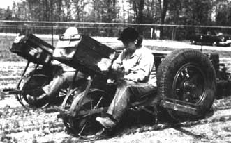
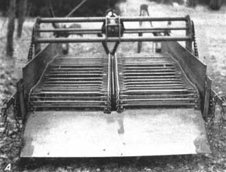
Most transplanting is now done with special machines developed originally to plant celery and other vegetable crops. The machines commonly consist of two transplanters mounted as a self-propelled unit (Figure 40). An operator places trees in each transplanter unit which then plants them in a trench opened and closed by the machine. A speed of from 40 to 50 trees per minute for each operator is attainable after training.
FIGURE 40. - Two-row transplanting machine. - Courtesy, Forest Service, U.S.D.A.
These self-propelled machines are also self-guided. Common practice is to make a 2- to 3-inch deep guide furrow across the field, using a V-shaped blade of some nature. The furrow must be carefully shaped and exactly located since it controls the work that follows. Some nurseries use two 1-inch iron pipes laid side by side for the furrow (Figure 41). These pipes serve as a track for a flanged front wheel.
To prevent deviating from the prescribed course, the machine must be kept balanced, particularly as concerns the draft placed on the power unit by the two planting units. The operators selected to thread the seedlings into the pockets on the revolving disks, therefore, should be of approximately the same weight.
The plant pockets on the revolving disk that sets the trees are spaced either 2 ¼- or 2 ½-inches apart on the disk. The speed at which the disk turns varies with the gear ratio used on the disk and the packing wheels that furnish the power to turn it. Therefore, the spacing of plants can be increased or decreased by adjusting the speed at which the disk turns. Standard spacing in, the United States Department of Agriculture Forest Service nurseries is 2 inches and a fraction, or approximately 5.4 seedlings per linear foot.
It is essential that the furrow-opening shoe be set deep enough to permit the roots of the seedlings to hang straight when they reach an upright position. If the seedlings are set at an angle, or the roots are planted in a horizontal position, deformations result which are difficult to handle when the trees are field planted.
Where more than one machine is operated in the same area, a foreman is usually assigned to supervise and direct the work. It is his duty to assist in turning the machines at the ends of the beds, to lay out new beds for planting, and to service the machines with seedlings. To avoid interruptions in the planting work, a supply of seedlings is kept at each end of the bed.
The production obtained by machine planting varies with the size and age class of seedlings planted, and the amount of ineffective time used in turning and servicing the machine. At a nursery in Michigan run by the Forest Service of the United States Department of Agriculture, where the length of beds ranged from 450 to 500 feet, a production of 30 thousand trees per 8-hour day was obtained with one two-operator machine.
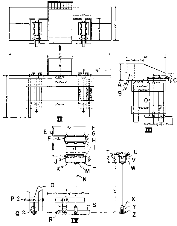
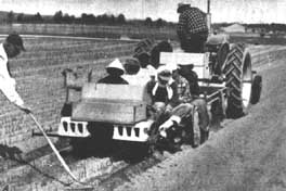
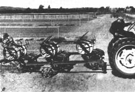
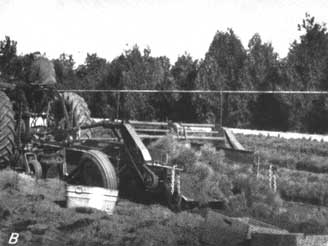
Self-propelled machines are used in some nurseries, others mount a battery of 6 to 8 planting units on a frame pulled by a tractor, as shown in Figure 42. Such a tractor must be equipped with Special gears so that it will move forward at a rate of only 8 to 10 feet a minute (Figure 43).
FIGURE 43. - Construction details for six-row transplanting machine. - Courtesy, Kimberly-Clark of Michigan, Inc.
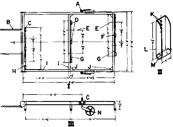
|
I |
Top plan |
|
II |
Hanger detail |
|
III |
Side view |
|
A. |
Drill swivel for removable lock pin in each wheel |
|
B. |
Farmall quick hitch drawbar coupler |
|
C. |
Cap - (½ × 1½ in.) |
|
D. |
Channel hanger (1¼ × 3 in.) |
|
E. |
Drill cross members to correspond to holes in hangers |
|
F. |
Center line of planter units |
|
G. |
Steel drawbar (1 × 48 in.) |
|
H. |
1-in. collard and setscrews hold bar in place; use same, size collars to hold planters in position |
|
1. |
Channel (1¼ × 4 in.) |
|
J. |
Steel fillet (3 × 3 in.) |
|
K. |
Drill 4 holes 1 in. apart for ½ × 1½-in. cap screws |
|
L. |
3-in. channel cut to fit tube |
|
M. |
1½-in. steel tube, ream; 1-in. still drawbar |
|
N. |
Swivel wheel |
Prior to the development of transplant machines, all transplanting was done either by hand or with a " transplant board." Operations using the transplant board can be very efficient, and the method has much to recommend it in places where machines are unavailable or are not justified by the amount of transplanting to be done. Various types of transplant boards have been designed by nurserymen based upon local requirements and personal preference. The types shown in Figures 44 are made of wood and serve the purpose well. If possible, this planting device should be made of aluminum or other light metal channels or angle bar shapes, because wood sometimes warps and fails to hold each seedling firmly in position. For a crew operating at maximum efficiency, three boards are needed for each planter - one board awaiting filling, one being filled, and one being planted.
FIGURE 44. - Construction details for a Bessey-type transplant board. - Courtesy, Forest Service, U.S.D.A.
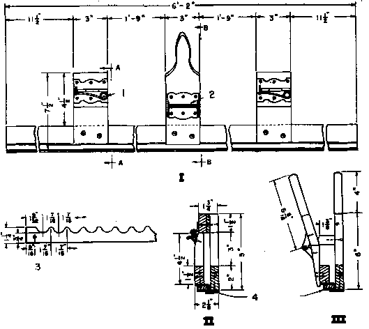
|
I |
Front elevation |
|
II |
Section A-A |
|
III |
Section B-B |
|
1. |
Holdback hinge |
|
2. |
Non-holdback hinge |
|
3. |
Metal strip (1/8 × 6 it. 2 in.) with notches filed smooth |
|
4. |
Rubber belting (1/8 × 3 in. × 6 it. 2 in.) |
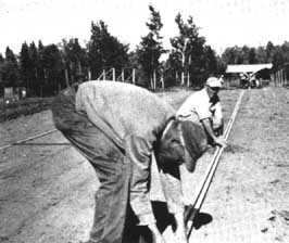
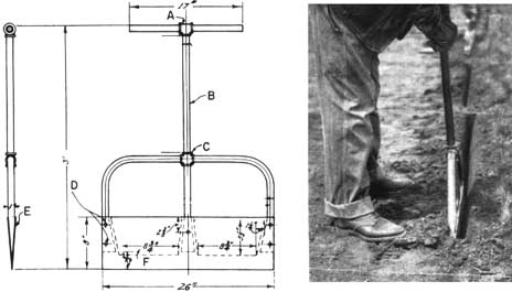
There is no " standard " length for transplant boards nor any " standard " spacing between seedlings; these factors vary according to local needs. Boards as long as 8 ½ feet and accommodating 75 trees have been used effectively in some places. In the operation pictured in Figure 45, the trench for the trees was being made with the hand trencher shown at the left of the board. An easier way is to open the trench with a tractor or horse-drawn trencher, the construction details of which appear in Figure 46. Lacking such a device, a plow can be made to serve.
FIGURE 45. - Transplanting with a hand board. - Courtesy, Forest Service, U.S.D.A
FIGURE 46. - Tractor-drawn device for opening transplant trench. - Courtesy, Forest Service, U.S.D.A.
|
I |
Top view of hitch |
|
II |
Ford tractor hitch attachment |
|
III |
Side view |
|
IV |
End view |
|
A. |
Drill (5/8 in.) |
|
B. |
Bolt (½ in.) |
|
C. |
U-bolt (½ in.) |
|
D. |
Steel plate (3/8 in.) |
|
E. |
Steel plate (5/8 in.) |
|
F. |
Steel plate (¼ in.) |
|
G. |
Weld |
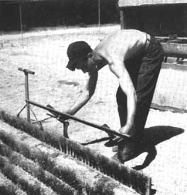
If relatively few trenches are needed or no traction equipment is available, a manual trencher will serve satisfactorily. In heavy soils, a workman with a spading fork may be required to loosen the soil immediately before trenching, despite previous plowing (Figure 47).
FIGURE 47. - Hand trencher and construction details. - Courtesy, Forest Service, U.S.D.A.
|
A. |
Standard malleable iron pipe tee. |
|
B. |
Frame and handle to be of ¾ in. iron pipe |
|
C. |
Standard malleable iron cross. D. Countersunk rivets (½ in.) |
|
E. |
Crucible steel plate (1/8 in.) |
|
F. |
Wood pieces inserted between plates |
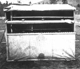
Because seedlings must be protected from drying out, their threading into transplant boards should be done in a shelter (Figure 48). The shelter commonly used in most nurseries is a skeleton frame made of light-weight material (Figure 49) and covered with canvas or with insect screening painted with a thick paint. Its front is left open, or canvas flaps hang loosely, to provide easy access for changing boards. If storage space is at a premium, the coops should be bolted together and disassembled for flat storage when not in use.
FIGURE 48. - Transplant coop. - Courtesy, Forest Service, U.S.D.A.
FIGURE 49. - Working drawing of transplant coop. - Courtesy, Forest Service, U.S.D.A.
|
I |
General plan |
|
II |
Section, A -A |
|
III |
Plan of shell |
|
A. |
Section (see II) |
|
B. |
Shell |
|
C. |
Comer shell |
|
D. |
Post |
|
E. |
Cleat |
|
F. |
Brace |
|
G. |
Shell braces |
Two shelves are provided in the shelter, one for the transplant board that is being filled and the other about 15 inches above for the empty board that is returned by the planter. The lower shelf should be placed at a convenient working height for the threader so that he can keep the boards filled at a steady pace. It is important that the shelter be long enough to accommodate the transplant boards. A portable oil heater or charcoal brazier will add much to the efficiency of the threaders on cold days.
If only one threader is used in a coop, he can save much time and walking by starting at one end of a board, completing and closing it. He then moves in the opposite direction as he fills the board that the planter has returned to him. Because the threader sees each seedling as he threads it, he should be trained to recognize inferior trees and instructed to discard them. If the work is proceeding very rapidly, two threaders are needed in each coop.
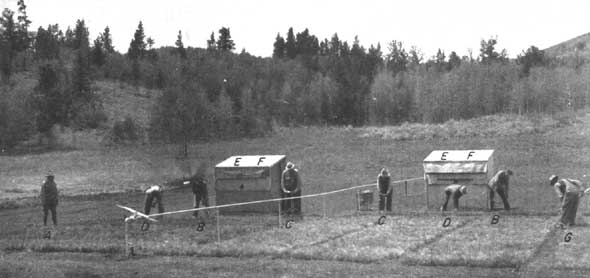
In small areas where long, continuous rows are impractical, an efficient organization can be developed to plant three beds simultaneously. In Figure 50, the rows of trees are being planted at right angles to the paths instead of parallel to them, but the other arrangement would be equally feasible. This system requires the least walking for the planter, because the coop is kept close to the planting front.
A transplant board of the Bessey type (without a spike to hold it in place during planting) is used in the following description in setting the seedlings:
1. The planter takes a filled board from the coop and walks to the open trench.2. At the trench, he stands with his weight on his heels far enough back to prevent caving in its walls, and with a slight swinging motion of the board lowers it so that the roots of the seedlings fall into their natural position in the trench.
3. Now he tilts the board away from him very slightly, rests it on the far side of the trench and, by shifting his weight to his toes, eaves in two small sections of the trench further to support the board. If this is correctly done, the board will now stay in the proper position without other holding.
4. He then lets go of the board, stands erect, and with the heel of one foot firmly tamps the soil around the roots of the seedlings as he moves from one end of the board to the other. (The process of opening the next trench will further tighten the soil around the tree roots.)
After tamping is completed, he opens the board and returns it to the top shelf of the coop, withdraws the full one which should be awaiting him on the bottom shelf, and repeats the process. If soil preparation and setting and tamping the trees are done properly, the additional work of removing excess dirt from the crowns of the plants and filling in low spots will be cut to a minimum.
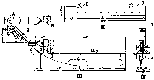
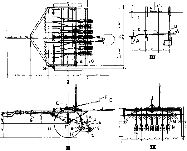
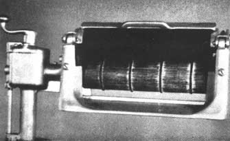
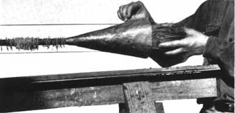
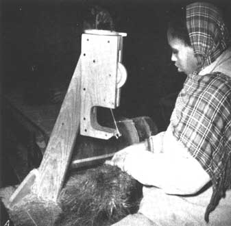
For planting sites where soil and climate are especially severe, it is best to produce trees in pots. Pots made at the nursery from 15-pound tar paper roofing felt to the size required for local conditions are satisfactory. Equipment for forming complete pots before filling need be hardly more than a paper cutter, two rollers, and a stapling machine. A wringer from a discarded washing machine (Figure 51) can be modified to serve admirably as a device for scoring paper.
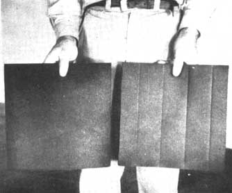
Prior to scoring, the paper is cut into individual pieces. The roll in which the paper is bought, can be sectioned to desired length with a power saw, and then into separate pieces by cutting them from the strip with a common papercutter. These pieces are then passed through the roller for the scoring (Figure 52).
FIGURE 52. - Paper before and after scoring. - Courtesy, Agricultural Research Service, U.S.D.A.
Because of this scoring, the paper folds readily into a rectangular tube that can be fastened with a hand-stapling machine. If a closed bottom is required, it can be formed by slitting the corners of one end of the tube with a clipper and interlacing the four tabs.
Although the scoring machine in Figure 51 was made by modifying the rollers of a powered washing- machine wringer, the same thing could be done equally well with a hand-powered roller made at a local carpenter or machine shop. The power is a convenience but not a necessity.
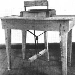
Such paper can also be formed into a pot by merely folding it around a wooden block of desired size, or more simply, by pushing it into a mold with such a block. A device to do this by foot power is shown in Figure 53.
FIGURE 53. - Foot-powered pot shaper. - Courtesy, Agricultural Research Service, U.S.D.A.
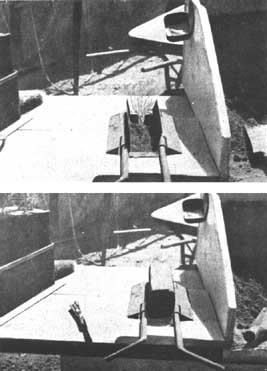
The device in Figure 54 permits forming the pot, filling it with soil and planting the tree in it in a concurrent series of operations. Details of its construction are shown in Figure 55. A sheet of the precut paper is pushed down into the potting box to form a trough. This trough is then half filled with soil and a seedling's roots are spread naturally on the soil.
FIGURE 55. - Construction details of potting machine bench (1 inch = 1 foot). - Courtesy, Soil Conservation Service, U.S.D.A.
|
I |
Top view |
|
II |
Front view |
|
III |
End view |
|
IV |
Detail of potter |
|
A. |
Slant bolts or nails for paper rack |
|
B. |
Bottom left open |
|
C. |
Slant 4-in. board to hold bark fill material |
|
D. |
Adjustable |
|
E. |
Handles ½ in. rod |
|
F. |
Fold edges out and bolt to table |
|
G. |
Cut ends of box ¾ to 1 in. longer |
|
I. |
Pipe (¾ × 1 in.) split and spread to take 318 in. round rod and welded to box for hinges |
|
H. |
Slot (½ × ¾ in.) 1 in. deep, for stem of plant |
|
J. |
Fold edges out allowing room for fin |
|
K. |
Rods (¼ in.) welded to bot tom of box for stops |
|
L. |
Floor plate |
|
M. |
Nut (½ in.) welded to center of floor plate |
|
N. |
½-in. round rod threaded |
|
O. |
Cut tapered slot in 2 × 4 in. for free movement |
|
P. |
Bolt (½ × 8 in.) |
|
Q. |
Strap (¼ × 2 in.) welded to form clevis |
|
R. |
Bend strap for foot pedal |
|
S. |
Length variable for counter balance |
|
T. |
Strap for fins (¼ × 2 in.) |
|
U. |
Weld fin to center of rod |
|
V. |
Fold edges out for pipe weld |
|
W. |
Edges between pipe sections cut and bent out to allow room for fin |
|
X. |
Lock nut for adjustment |
|
Y. |
Clevis or turnbuckle (½ × 2 in.) |
|
Z. |
Bolts (½ in.) |
The remaining half of the soil is then placed on the roots and the pot is completed by turning the handles to overlap the projecting edges of the paper. They are fastened together with a hand stapler. The whole operation takes but a few seconds. The potted plant is ejected upwards from the form by pressing the foot lever.
In nurseries large enough to justify the cost of a power-spraying machine, it is now standard practice to do the weeding in conifer seedbeds with selective sprays that kill the weeds but spare the trees. Prior to 1942, selective weed sprays were unknown to the nurserymen. Soil treatments to kill weed seed in advance of seedbed sowing were in use but were not very satisfactory. The possibilities of weedicide sprays were demonstrated by certain vegetable growers, and at the guayule rubber plant nurseries in 1943-45. By 1949, the technique had become widespread.
The product most generally used for this purpose at present is " mineral spirits." This is also known as white spirits of petroleum in many European countries. In America, it is sold under a variety of trade names by various oil companies. Derived from napthenic petroleum, mineral spirits have an initial boiling point of 300° to 320° F., an API gravity of 48 to 50, and an aromatic hydrocarbon content of 10 to 20 percent. Weed kill appears to be approximately proportionate to the aromatic content of the product being used.
Pines, spruces, firs, and junipers tolerate mineral spirits, but other conifers, notably the larches, do not. Some tree species are moderately sensitive and may show injury if more than 40 gallons per acre are applied in any one treatment. Still other species, such as red and jack pine, appear to tolerate as much as 80 to 100 or more gallons per acre of spray with little or no harmful effect. Local experimentation is required to determine the effectiveness of the spray at specific nurseries. Its use on hardwood species is not recommended, unless local tests have clearly demonstrated that it will not injure them.
Much research is underway in this method of weed control and the techniques are gradually being improved.
The technique and equipment used at present is as follows:
1. Equip sprayer with low-pressure manifolds to permit capacity spraying for weed control and high-capacity spraying with insecticides or fungicides; and add teejet nozzles that throw a fan-shaped spray. Nozzles should have 100-mesh screens and be spaced 20 inches apart on a boom 17 to 19 inches above the bed.2. Keep the working pressure below 60 pounds per square inch to avoid " fogging." Fogging causes wind drift, which results in irregular application and sometimes severely injures pines.
3. Regulate rate to avoid overdosage. Start -spraying 10 to 14 days after removal of seedbed covers or after seedlings emerging through mulch have acquired a healthy green color; apply 10 to 12 gallons per acre 2 to 4 times a week. Later, applications of 25 gallons an acre about once a week are satisfactory. Heavy mortality has followed application of 40 to 80 gallons an acre on very young seedlings.
4. Water the seedbeds several hours before spraying, except right after a rain. Water the older and larger seedlings more heavily. Do not spray seedlings while the foliage is still wet it they have secondary needles, as injury results. Do not water beds immediately after spraying, because heavy watering or rain soon after spraying reduces the effect on weeds.
5. During the first few sprays of the growing season, avoid spraying at excessively high temperatures and at temperatures below 60° to 75° F.; spraying at excessively high temperatures increases injury to pines, and at the lower ones, decreases weed killing. Spraying at high temperatures, in general, has not injured seedlings and has increased the rapidity and completeness of weed kill.
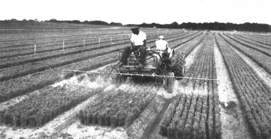
Suitable spray machines are commercially available from any agricultural equipment dealer. For nursery use, the machine is usually equipped with a spray boom wide enough to cover three beds at a time but hinged to fold back upon itself to facilitate movement from place to place (Figure 56). It is also desirable that the boom be equipped with an angled nozzle with shut-off valve at each end to permit spraying into fence rows or other obstructions, and with shut-off valves within the boom itself so that part of it can be closed if desired. A screen or filter in the line between the tank and the pump to trap solid particles will save the annoyance of clogged nozzles.
FIGURE 56. - Trailer type of spraying machine. - Courtesy, Forest Service, U.S.D.A.
Nurseries of such size as to require large-capacity tanks usually carry them on a trailer pulled behind a tractor. Such units may be powered by a separate motor to operate the pump or with a pump mounted on the tractor. The man riding the trailer operates the control valves, watches for clogged nozzles, and raises the boom or sections of it to facilitate turning or passing over terraces. However, it is possible to design the machine so as to avoid use of this extra man.
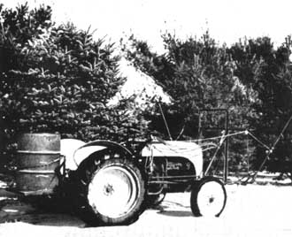
Some nurseries find it practical to mount a tank (as an oil drum) directly onto the back of a tractor and power the spray pump with the power take-off or the engine's fan belt (Figure 57). Such a piece of equipment can be assembled by a mechanic from commercially available parts and need not be at all costly.
The use of a backpack or hand-carried sprayer, either self-powered or manually powered, to spray small areas with weed killer is not recommended. With a manually directed nozzle, it is most difficult to obtain a uniform distribution of the required amount of material. As a result, the seedlings in parts of the bed may be killed or stunted, while the weeds in others receive less than an effective dose and remain unaffected. Nurseries with only a few beds or with experimental beds had better rely on hand weeding.
A wide variety of soil fumigants have been introduced into nursery work in the last few years. In varying degree, they eliminate all weeds, diseases, nematodes, and insects. Nurseries occasionally report spectacular benefits of improved germination, seedling vigor, etc., after using them. When fully successful, they eliminate nearly all weeding for the year, and greatly reduce it for several years to come. Their use is especially valuable to eradicate weeds that propagate from rhizomes, stolons, or bulbs and thus resist hand pulling, hoeing or spraying. Unfortunately, the most effective fumigants are very costly, dangerous to handle without skilled labor, and may require costly special equipment. No one of them has come into common use, and general recommendation cannot be made. Information concerning these products can be obtained from dealers in agricultural chemicals.
Controlling weeds by hand methods in storage areas, on road shoulders, and in other places where plant growth is unsightly or unwanted can he costly in large nurseries. Specialized chemicals have recently been developed to sterilize soil and prevent all plant growth for periods of a year or more, the duration of the treatment depending upon the rate of application. Information concerning these products can be obtained from dealers in agricultural chemicals.
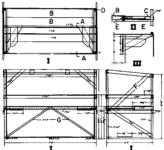
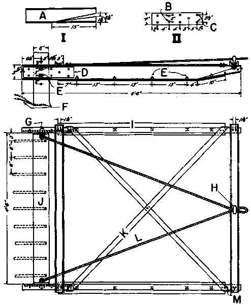
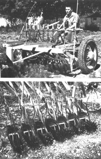
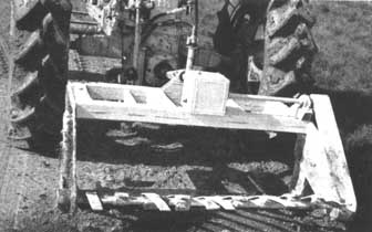
Cultivators that operate from behind a tractor can be built to cultivate and kill weeds between rows of trees, as in seedbeds sown in drills. Such a cultivator, first designed at an Illinois State nursery and later improved at a Tennessee Valley Authority nursery, is shown in Figures 58 and 59. The operator on the cultivator can move it to the right or left by pushing on the tiller bar and thus guide the machine between crooked rows of trees.
FIGURE 59. - Construction details of seedbed cultivator. - Courtesy, Tennessee Valley Authority.
|
I |
General plan |
|
II |
Side view |
|
III |
Detail "E" |
|
IV |
End view |
|
A. |
Bar |
|
B. |
Sliding bar |
|
C. |
Bar frame |
|
D. |
Bolt |
|
E. |
See II |
|
F. |
Cultivators controlled as a unit by steering mechanism. See II |
|
G. |
Standard pipe (2 in.) |
|
H. |
Wheel |
|
I. |
Slot (2 in.) for adjustment |
|
J. |
Foot rest |
|
K. |
4 wheels from pulverizer attachment |
|
L. |
3 prongs from 5-prong weeder |
|
M. |
Collar |
|
N. |
Stand pipe (¾ in.) for spacers |
There seems to be an almost infinite variety of insects and diseases that attack seedlings in every stage of development and every part of root and shoot. The seriousness of such pests and plagues differ for the various tree species and even among localities in which nurseries grow the same species. Hence, cures or preventatives that, are simple and 100 percent effective in some places or during some years, fail utterly in other places and times. Direct correspondence with entomologists, pathologists, and other appropriate technicians at research stations in the affected locality, or in similar localities, is the best means of obtaining specific information on any particular problem.
Pests and plagues are frequently fought by the application of certain sprays. Sprayings equipment used in weed control work is equally useful in this type of work.
In combating certain diseases, there has recently come into use a technique of applying protective coatings of suitable chemicals to seed prior to sowing. This is spoken of as "pelleting " the seed, and it is quite effective. It consists of first coating the seed with a " sticker," and then coating it with an effective chemical or chemicals. After drying, the seed is then sown in the normal manner. Allowances must be made in the sowing rate for the increased size and weight of pelleted seed.
The sticker is applied by pouring an appropriate quantity over the seed which is then tumbled in some sort of a revolving drum. Sticker compounds made from methyl cellulose or latex are on the market. Either serves the purpose well. After the seed are evenly coated with the sticker, an effective chemical is put in and the tumbling continued until all seed are uniformly coated. If desired, a second chemical, such as a bird repellant, can be applied in the same manner without additional sticker. After coating, the seed is spread on a tray or sheet to air dry. The treating process works best on small batches, and it should take but 3 or 4 minutes for a 10-pound batch. Excessive tumbling should be avoided to prevent chipping or damage to the seed, and the dry seed should not he rubbed more than necessary because-the protective coat may be damaged.
A small concrete mixer with a capacity of I cubic foot is commonly used in this work, but any can or box on a handcrank or foot treadle would serve. For a 10-pound batch of seed, a United States Forest Service nursery in Indiana uses a 20-gallon drum. On a small-scale job, the work can be done without any machinery; it is perfectly practical to pour the sticker or the effective chemical over the seed and then stir it by hand or pour it from one vessel to another until distribution is achieved.
Until recently, bird and rodent depredations were a serious cause of loss in newly-sown or germinating seedbeds, and elaborate protective screens were necessary. These were costly to build, to maintain, and to put in place and remove. The discovery of effective repellants and the development of the pelleting technique have eliminated this problem at nurseries using the technique.
The chemicals in general use at present are sublimed anthroquinone or tetramethylthiuram-disulphide 50 percent (50 percent TMTD). Some nurseries prefer the latter because it offers some protection against rodents and is also effective (as in Wisconsin) as a control for the damping-off disease. However, other nurseries feel that it has a slight retarding effect upon germination and prefer to use anthroquinone with a specific rodent repellant added.
The quantities of the chemical required for 100 pounds of seed (loblolly pine and slash pine) is 16.6 pounds of the 50 percent TMTD, or 20-pounds of the anthroquinone. They are applied as coatings to the seed in the manner described under the section on insect and disease control.
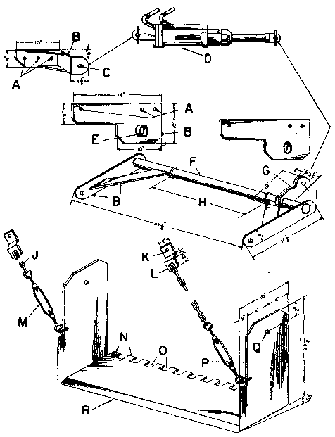
In large nurseries where labor is scarce and costly, the manual digging of trees is impractical. Many models of mechanical lifters have been developed to lift the soil and loosen trees so that they are easy to pull by hand without additional digging. The various models presented here are only illustrative of the general idea. There are others that perform equally well.
The sled type lifter shown in Figure 60 can be pulled directly behind a tractor, or by a cable to a powered winch. If a suitable tractor or winch is unavailable, it can be pulled with a cable to a capstan turned by a team of horses. The latter is in fact the original method used for this model of lifter. The design for a cable carrier is shown in Figure 61.
FIGURE 60. - Construction details of sled-type digger for pulling with cable to a tractor or capstan. - Courtesy, Forest Service, U.S.D.A.
|
I |
Detail of cutting runner |
|
II |
Detail of plate |
|
A. |
Cut web before bending |
|
B. |
Bolts (13/16 in. for ¾ in.) |
|
C. |
Rivets (9/16 in. for ½ in.) |
|
D. |
Plate |
|
E. |
Plow bolt |
|
F. |
Shakers to be riveted on for digger, removed when used as a root pruner |
|
G. |
Eye bolt (¾ × 5 in.) |
|
H. |
Eye (1½ in.) |
|
I. |
Steel shoe |
|
J. |
Old road scraper shore |
|
K. |
Steel plate |
|
L. |
Steel cable |
|
M. |
Bolts (3/8 in.) |
FIGURE 61. - Cable carrier, required to carry cable and prevent it from damaging trees. Courtesy, Forest Service, U.S.D.A.
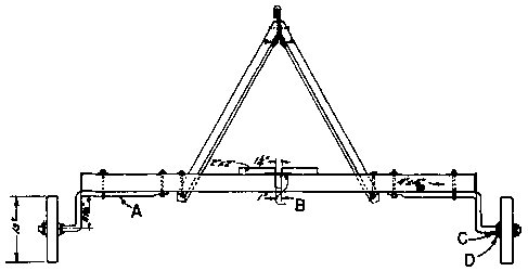
|
A. |
Steel axle (1 in.) total length 33 in. |
|
B. |
Thin metal plate under 2 ×2 in. |
|
C. |
Cotter pins (¼ × 1½ in.) |
|
D. |
Washers between wheels and cotter pins |
Tree lifters that vibrate and thus shake the soil from the roots of the trees being dug have been developed at some nurseries. They loosen the soil more than the other types and thus facilitate getting the trees out of the soil with less damage to the small roots. On such diggers, the heavy digging blade itself does not vibrate but fingerlike strips that extend backwards from the blade are vibrated up and down by a camshaft driven by a chain to a power unit mounted at some convenient place above the digger, or driven by the power take-off of the tractor. A plan and bill of material for a machine developed at the United States Forest Service nursery in Eveleth, Minnesota, are shown in Figure 62.
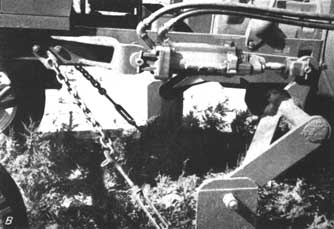
Another type of vibrating tree lifter, which removes nearly all of the soil from the roots, is used at several Pennsylvania State nurseries and at the United States Forest Service Chittenden nursery in Michigan (Figure 63). It is nothing more than a two-row mechanical potato digger, and it works well in certain soils when the seedlings are of sufficient size and density.
FIGURE 63. - B. Potato digger at work. - Courtesy, Forest Service, U.S.D.A.
For such a digger to serve satisfactorily, the trees should be 4 inches or more tall and dense enough to have their needles interlacing to some extent. Tiny trees will shake through the shaker chain belt, and scattered trees will fall over and become a hopelessly jumbled mass. This type of machine does not operate well in soils that hold together and resist shaking.
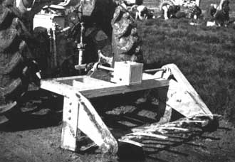
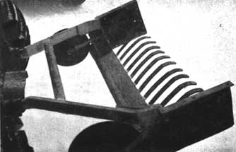
The lifter pictured in Figure 64 hangs from the center of a wheeled tractor in a position where it can be watched by the driver as he steers the tractor. He can raise or lower it immediately with the hydraulic controls he has at his finger tips. It was developed at the North Dakota State nursery at Towner, North Dakota, and does its work well. It is simple, rugged, and quick to respond to the tractor driver's control. Only 4 bolts are used to attach or remove it from the tractor. Construction details are shown in Figure 65.
FIGURE 65. - Construction details of litter. - Courtesy, North Dakota State Forestry Department
|
A. |
Holes (5/8 in.) for bolts to tractor |
|
B. |
Material (5/8 in.) |
|
C. |
Hole (1 in.) to receive pump |
|
D. |
Standard John Deere pump |
|
E. |
Sleeve to receive 2½ in. shaft |
|
F. |
Cold rolled steel shaft (2½ -in.) |
|
G. |
Stock (1 inch) made by welding two ½ in. Plates |
|
H. |
Distance of keeper rings depends on tractor width |
|
I. |
Hole to receive 1 in. pump pin |
|
J. |
Chain (3/8 in.) |
|
K. |
Hole (5/8 in.) |
|
L. |
Material (½ in.) |
|
M. |
Turnbuckle (5/8 in.) |
|
N. |
Teeth (3/8 × 2 in.) |
|
O. |
Space (7/8 in.) |
|
P. |
Material (¾ in.) |
|
Q. |
Hole (1 in.) |
|
R. |
The 2 in. cutting edge was taken from a worn maintainer blade (road grader). |
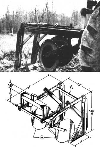
A lifter for attachment behind a tractor is shown in Figure 66, and its construction details in Figure 67. This was developed at the Michigan State University nursery at Sault St. Marie, Michigan. It can be used with either a wheeled tractor or a crawler tractor that has a suitable hydraulic-hitch mechanism.
FIGURE 67. - Construction details for rear-mounted lifter. - Courtesy, Forestry Department, Michigan State University
|
I |
Top view |
|
II |
Front View |
|
III |
Side view |
|
1. |
Car spring leaf (¼ × 1 ¾ × 18 in.) |
|
2. |
Plate shield (1/8 × 16 × 16 in.) |
|
3. |
Tractor hitch (1 × 3 × 42 in.) |
|
4. |
Welder brace (½ × 4 × 9½ in.) |
|
5. |
T-iron sprocket/brace (3/8 × 1½ × 15 in.) |
|
6. |
Iron sprocket/brace (3/8 × 1½ × 12 in.) |
|
7. |
Coulter (16 in. with ½ in. diam. axle) |
|
8. |
Iron pipe (2½ in. outside diam. × 28 in.) |
|
9. |
Grader blade (8 in.) |
|
10. |
Plow bolts (½ in. diam.) with nuts at bottom of blade |
The one-row tree lifter (Figure 68) is especially suitable for use on hardwoods lined out into rows. It was built by the Institute of Paper Chemistry tree genetics nursery at Appleton, Wisconsin. The lifter is designed for use behind a tractor with a three-point hydraulic hitch. By means of this hydraulic control, the lifter can be run at any desired depth from 0 to 9 inches. The 18-inch rolling coulters, which are mounted on the frame in front of the lifter shoe, prune the side roots. The lifter shoe prunes the lower roots, lifts the trees, and loosens the soil with a minimum of injury to the root system.
|
A. |
Pipe (2 in.) |
|
B. |
Coulter (19 in.) |
Operating lifters on heavy soils when the ground is too dry or too wet, or at too great a speed under any condition, breaks many seedling roots; there is a consequent reduction of vigor or death of such seedling-, when planted. After the lifter has undercut the seedlings, care must still be used in getting their roots out of the ground, by hand or with forks or shovels, because there may be further breaking of the roots or stripping of their bark. Supervision of the lifting should include occasional sifting of the seedbed soil as well as close scrutiny of washed trees to learn the extent of root damage. Changes in tractor speed, blade angle, and laborer techniques or a wait for proper soil-moisture conditions, may be required to reduce such damage.
There is no " standard " or " best " way to organize this phase of the work. Organization varies according to size of trees, required output per day, kind of labor, and demands of the customers. Some nurseries that produce trees of uniform size do not grade or count their stock they ship it bed-run with little or no attention to actual quantities. When it is necessary to determine total quantity, they weigh a given number of trees (1,004) or 10,000); this weight is then used as a gauge for quantity in filling the order. But other nurseries must grade their stock, discard substandard plants, and obtain ail accurate count.
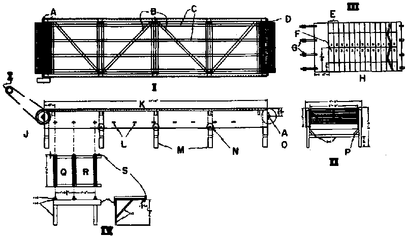
Where grading and counting are required, the work should be done in a building so the trees are protected from sun and wind. Such work is greatly expedited if a grading table with a conveyor belt is used to carry the trees from the people doing the grading to the packers.
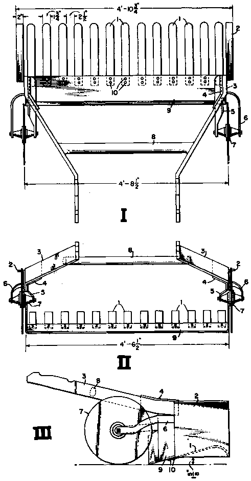
The grading table shown in Figure 69 was developed at state nurseries in New York and has been duplicated elsewhere, often modified in length, width, or other details to fit local conditions, The belt has numbered spaces painted on its surface, each number a different color, to aid the graders in their work. At, the New Jersey State nursery, the table belt was operated at a speed of 1 revolution per 59 seconds, with 5 persons on each side placing 2 trees in their assigned spaces. With such an organization, it delivered 300 trees per minute to the packers who tied them into bundles and packed the bundles into boxes or bales for shipment.
|
A. |
Brozoli bearings (1¼ in.) |
|
B. |
Cross members (2 × 4) |
|
C. |
Longitudinals (1 × 2) spaced 3 in. from sides, 13 in. in center - 4 in all. |
|
D. |
Clearance (1 in.) |
|
E. |
Space (10 in) between wood ribs on inside of belt |
|
F. |
Stencilled 2 in. numbers |
|
G. |
Straps and buckles |
|
H. |
Three platform aprons (45 × 159 in.) |
|
I. |
Motor to pulleys to overhead shaft |
|
J. |
V-pulleys from 20-1 reduction gear or overhead shafts and belting for reducing from motor to table |
|
K. |
Belt travel: 60 seconds per revolution |
|
L. |
Holes for box racks |
|
M. |
Legs (2 × 4) |
|
N. |
Three rollers (4 to 6 in.) |
|
O. |
Shaft (1¼ in.) or pipe (1 in.) |
|
P. |
Braces on end legs only |
|
Q. |
Box. Box size should be 16 × 27 × 8 in. high outside. |
|
R. |
Man stands here. 5 men to each side |
|
S. |
Ends of 1 × 3 fit into holes in sides of table |
A nursery of the State University of Michigan found it advantageous to have each grader count a full bundle of 50, fasten it with a rubber band, and place it on the belt that took it to the packer. The organization it found best is shown in Figure 70. Ten graders, three packers, and one clerk achieved an output of 120,000 to 175,000 trees per day with this organization.
FIGURE 70. - Suggested organization for counting and, parking. - Courtesy, Forestry Department, Michigan State University
|
A. |
Movable stools |
|
B. |
Conveyor |
|
C. |
Grading table |
|
D. |
Gone mounts |
|
E. |
Gone |
|
F. |
File |
|
G. |
Clerks' desk |
|
H. |
Table for trees |
|
I. |
Moss tank |
|
J. |
Overhead pipe |
|
K. |
Shipping ticket rack hung from ceiling |
|
L. |
Packing table |
|
M. |
Hose suspended from ceiling to dampen roots |
|
N. |
Rolls of paper under table |
For various reasons, some nurseries tie the trees into bundles of 50 or 100, or other convenient unit ' before packing them into a large bale. To do this by hand has proved costly, because hand-tying is too slow and the maintenance of tying machines is sometimes a problem.
The state nurseries in Alabama found that rubber bands of a size selected to accommodate a given size of bundle were satisfactory but slow and difficult to apply. To speed the work, they made the device pictured in Figure 71. This device is nothing more than a sheet of metal formed into a funnel and fastened to a horizontal support. A quantity of rubber bands is placed onto the holder in advance of packing. The roots of the bundle of trees are inserted into the funnel and a band pulled over it and onto the bundle. Rubber bands of different colors are sometimes used as a code to designate species, age class, or other such diversities.
The state nursery in Virginia prefers to use tape instead of rubber bands. The tape used is 3/8-inch pressure-sensitive cellophane which is commercially available in 60-yard rolls in any of six colors. With the device shown in Figures 72 and 73, an experienced workman can fasten bundles at the rate of about 10 per minute.
FIGURE 72. - A. Tape dispenser ready for next bundle. - Courtesy, Virginia State Forestry Department
FIGURE 72. - B. Taped bundle ready for packing. - Courtesy, Virginia State Forestry Department
FIGURE 73. - Construction details of tape dispenser. - Courtesy, Virginia State Forestry Department
|
I |
Tying Position |
|
II |
Cutting position |
|
A. |
Pin (¼ in.) for spare 3-inch wheel and roll of tape |
|
B. |
Pin (¼ in.) |
|
C. |
Wood screws (8 × 1 ¼ in.) |
|
D. |
Roll of tape |
|
E. |
Wood wheel (3 in. diameter) cut from ¾ in. pine |
|
F. |
Wood wheel (1 ½ in. diameter) ditto |
|
G. |
Glue side |
|
H. |
Removable pin |
|
I. |
Two cutters, one over the other |
|
J. |
Glue to glue |
|
K. |
Tape |
|
L. |
50 seedlings |
|
M. |
Tape, left ready for next bundle |
|
N. |
Bundle |
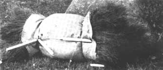
All manner of shipment systems, such as wooden crates, paper boxes, or bulk packing on the bed of a truck, are used, Each system fits local conditions very well, and need not be discussed here. But for bulk shipments that must withstand the rigors of public transportation systems, storage, and rehandling, the round bale made with wet moss and waterproof paper (Figure 74) has been found cheaper and superior to the others.
The Ontario Department of Lands and Forests has demonstrated that bales of trees can be delivered satisfactorily by free fall from an airplane. The bale pictured in Figure 75 bounced and tumbled about 30 feet between impact and stopping place without significant damage to the trees. Directions for preparing such bales follow:
Equipment
1. Tank or trough for soaking sphagnum moss or substitute.2. Fork for handling wet moss.
3. Wooden or reinforced hardware-cloth screen for draining excess water from moss.
4. For each baler, a table at least 4 feet long × 2½ feet wide, of convenient height, with 10- or 12-inch side supports.
5. For each baler, a strapping machine or wire-tying machine using 3/8-inch strap or No. 12 wire. (Despite the cost, it is cheaper to have one or two extra machines on hand than to incur a breakdown in packing through the failure of one.)
Material per bale
1. Two wooden slats, 1 × 2 × 24 inches. (For very tall seedlings, 36-inch slats.)2. One waterproof wrapper 6 × 2 feet (for very tall seedlings, 6 × 3 feet), of 7-ounce burlap backed with asphalt and kraft paper, or of heavy waterproof crepe paper reinforced with sisal fibres. (The essentials are (a) sufficient toughness to stand packing and shipping; and (b) resistance to water sufficient to keep bale from drying out and, if bales are shipped by express, to meet common-carrier's requirements about avoiding injury to other merchandise. Some nurseries print the nursery name and instructions for watering. It is also feasible to print tree planting instructions on waterproof paper and include a copy in the bale where it will be found by the planter when he opens it.)
3. Supply of sphagnum moss.
4. Two 3/8-inch by approximately 5-foot metal straps, or equivalent wires, to fit make of strapping machine or wire-tying machine used.
5. Two fastening seals.
Bating instructions
1. Lay two straps across the table, about 18 inches apart. (The distance apart depends on the size of the seedlings and the way they go together in the bale, as explained in 5 and 10, following.)2. Lay one slat at right angles across the straps.
3. Lay a wrapper, with its long dimension across the table, on top of the straps and slat.
4. Across almost the full width of the wrapper spread a layer of drained or wrung-out sphagnum moss 18 to 24 inches wide from front to back, and thick enough (2 ½ to 3 inches) to protect the seedlings.
5. On the layer of moss place loose or bundled seedlings with the sparser lower parts of their root systems overlapping the centerline of the wrapper and their root collars well inside the edges of the wrapper, but at least the tips of their needles projecting well beyond the wrapper. The seedling tops, however, should not project so far beyond the wrapper as to flop loose or to be injured in handling the bale. The layer of seedlings should not be more than 3 to 4 inches thick. The exact position of the seedlings depends mainly on their size. On each side of the layer the root collars should be about equally distant from the edge of the wrapper.
6. Spread 2 to 3 inches of moss over the roots and far enough up to the stems to cover the root collars and to maintain the thickness of the bale to a point slightly outside the strap on either side. The moss must extend beyond the seedlings, both front and back, to meet the first layer of moss.
7. Repeat steps 5 and 6 until the bale is the desired size, ending with a top layer of moss 2 ½ to 3 inches thick. (Numerous thin layers of seedlings and moss require little more labor than fewer, thicker layers, and make a better bale, especially for long shipment or several days' storage.) Bales are commonly made to weigh about 60 pounds apiece, before supplementary watering, letting the number of seedlings per bale vary according to the size of the stock. With a little practice, checked by weighing of bales, most bales can be made remarkably uniform.
8. Make sure that there is everywhere at least a 2 ½ to 3-inch layer of moss between the wrapper and the nearest seedling roots; bring the two ends of the wrapper neatly together in a double layer above the top of the bale.
9. Take the second slat and roll both ends of the wrapper jointly around it until the wrapper has pulled the bale together as tightly as can be managed conveniently by hand.
10. Bring the straps around the bale; tighten each firmly but not crushingly with the strapping machine (Figure 76); seal and cut off. The straps must go around the bale fairly near the edges of the wrapper and somewhat above the root collars, of the seedlings (less far, but still definitely above, in the case of longleaf pine) in such a way that rough handling cannot cause the seedlings or straps to loosen or shift, or seedlings or moss to fan out.
11. The finished bales are kept on their sides but may be stood on end, temporarily, for watering and draining before or during shipment or storage.
No two nurseries start with identical soils nor make exactly equal demands upon these soils. Thus, no course of soil management can be uniformly prescribed. Yet, general principles apply to all, and the following recommendations from the U.S. Department of Agriculture's
Agriculture Monograph No. 18, could be generally adapted in various regions after suitable local trials.
1. Erosion must be controlled. Mechanical packing, working of heavy soils when very wet, mixing of heavy subsoil into surface soil, excessive watering, and other procedures which may injure the soil physically should be avoided, or reduced in every possible way.2. Soil organic matter should be built up to and maintained at a 1.5 to 2.0 percent level by the use of green manure crops, composts, or organic soil amendments. Soils very low in organic matter may require annual or alternate-year applications of 10, 20, or even 40 tons of compost or organic supplements per acre.
3. Fertilizers and other substances added to the soil preferably should be chosen to produce and maintain a pH concentration of slightly above 5.0, but not above 6.0.
4. Unless they result in succulent or oversize stock incapable of good plantation survival, additions of nutrient elements to the nursery soil should at least equal and possibly greatly exceed the average annual quantities required locally for agricultural crops. Phosphorus and nitrogen are especially likely to be required.
5. Any nutrient element added in inorganic form before sowing pines should be applied cautiously in small to moderate quantities. Instead, either periodic additions during the growing season or moderate to heavy applications to the green manure crops may be preferable. Such additions might also be a means of supplementing the additions made before sowing.
6. Applications of lime should be avoided unless there is definite evidence of need for them. If such applications are needed, they should be made before green manure crops rather than before pines. Large applications of easily soluble inorganic nitrogen carriers, such as sodium nitrate, or of easily decomposed organic nitrogen carriers, such as cottonseed meal or dried blood, should not be made when or just before sowing pines. Also, they should not be made a short time before lifting.
7. In preference to being left bare for periods of some months, nursery soil should be sown to cover and catch crops that reduce erosion, keep down weeds, and prevent deterioration of soil structure and leaching of nutrients. Even a cover of weeds may reduce erosion and leaching and return a net benefit if disked in before producing seed or rhizomes.
8. Green manure, cover, and catch crops may have to be selected for their resistance to nematodes. During the winter and spring and until about July, such crops must be watched closely as a source of cutworm outbreaks.
9. Green manure, cover, and catch crops must be plowed in long enough before pines are sown to permit decomposition. One month is about the minimum safe period. Much longer is necessary with very heavy crops.
10. Large applications of organic matter, such as straw, sawdust, or even nonleguminous green manure crops, should not be turned in before a pine seedling crop without adding enough nutrients, especially nitrogen, to supply the micro-organisms that decompose cellulose.
11. Fertilizers should not be incorporated in compost to the extent of more than about 4 percent by weight of nutrient salts, based on airdry weight of the compost material.
12. Materials and practices deserving of local trial are as follows: Previously little-used raw materials (especially sawdust) for composts and organic supplements; slowly soluble carriers of nutrient elements, especially for green manure crops or for application before sowing pines; application of inorganic nutrient carriers periodically during the growing season but with care to wash them off the foliage promptly if applied in liquid form; moderate late-season applications of potassium (which seem to improve survival); building up soil organic matter by applying sawdust and nitrogen to legume green manure crops; and leaving late-summer green manure crops on the ground as a mulch over winter instead of turning them under in the fall.
13. If seedling development is poor and no mycorrhiza can be seen on the roots, inoculation of the beds with mycorrhizal soil or cultures should be tried as a means of improvement.
14. The final proof of the effectiveness of any nursery soil treatment, over and above its cost and its visible effect on the soil, is the plantation behavior of the seedlings it produces. The size and appearance of seedlings are not reliable evidence of their quality. Any drastic change in fertilizer treatment requires planting of the treated seedlings to verify their capacity for high initial survival.
In general, the techniques and machines described in this manual are equally adapted to the production of hardwoods or conifers. For example, the beds for either type of stock are generally made in the same manner and size. Seeding machines for conifers are satisfactory for some hardwood seeds and can be modified to serve for others. The transplanting equipment shown will serve for planting hardwood cuttings, as well as for rooted seedlings of either hardwoods or conifers. Similarly the diggers and the packing equipment is the same for either class of stock.
One important difference, which must be observed until local experimentation has shown otherwise, is that hardwoods are more susceptible to serious damage from the application of oil or chemicals to control weeds. Hardwood weeding can be expedited if the bed is sown with the seed in bands or rows and then cultivated with the powered cultivator shown in Figure 58 on page 73.
The diagrams for this article have been reproduced in as much detail as practicable but cannot be definitive. Readers requiring working drawings should refer to the author. The first part of the manual was printed in the last number of Unasylva and is now available as one reprint.
NOTE: 1 inch = 2.54 centimeters; 1 foot = 30.48 centimeters; 1 square foot = 0.0929 square meter; 1 acre = 0.4 hectare; 1 gallon = 4.54 liters; 1 pound = 0.45 kilogram.
![]()
![]()
![]()