The SIMRAD EY-M echo sounder used in this exercise is a small portable unit designed for operation in freshwater lakes. The operating frequency is 70 kHz. It has two time-varied-gain (TVG) controls of “40 log R” and “20 log R”, which compensate for spreading and absorption of the echo signal. The echo signals are shifted down from 70 kHz to 10 kHz at the calibrated signal output. This makes it possible to record the analog signals on an ordinary high-fidelity tape recorder. During the Bodensee experiment, all data were recorded with a “40 log R” TVG applied to the echo sounder preamplifier. The analog echo signals were recorded on a SONY TC-D5M tape recorder.
SIMRAD has developed a multi-element ceramic transducer for the EY-M sounder. It is a narrow-beam transducer with a circular beam pattern. The beam angle of the actual transducer used in the exercise was found by measurement to be 11.2 degrees at the -3 dB level. By substituting this angle in the theoretical directivity function b (θ) for a circular transducer, the effective diameter was found. From this, the directivity pattern was determined, and the beam split into ten 2-dB classes.

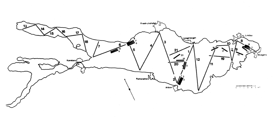
Figure 1 Transects of hydroacoustic survey and trawling made in Lake Constance, 24 – 27 Oct. 1983. Dotted lines: hydroacoustic transects; solid lines: trawling
The transducer was mounted on a V-fin and suspended about 0.5 m from the side of the boat. The speed was kept constant during the transects. Dependent on the boats used, this coud vary between 2–3 m/s. The transducer was towed at a depth of 0.5 m from the side of the boat. It was towed at a depth of 1 m. This form of mounting is preferable when operating from small boats. It gives the transducer good stability in the water, and it is easy to remove it from noise sources such as the motor and propeller. However, the TVG function starts at a depth of 2 m, and this mounting will therefore exclude fish located in the upper 2 – 3 m.
The echo amplitudes are reproduced from the recorded 10-kHz analog signal in an AC/DC converter, and the envelope sampled every 0.1 ms by an 8-bit analog-to-digital converter. The digital signals are stored on floppy disks by a Mostek FLP-80 micro computer. The same computer is used when running the analysing algorithm.
By using an echo sounder with a “40 log R” time-varied-gain (TVG) the received echo signals are independent of range. The echo amplitude then depends only on the angular coordinates of the target. The directivity pattern of the system is obtained by combining the transmit and receive directivity from the transducer. In this experiment, the directivity pattern was divided into 2-dB class intervals.
By applying the simple algorithm proposed by Craig and Forbes in 1969, it is possible to remove the effect of the beam pattern from the received echo distribution. It statistically transforms the echo distribution to a target strength (TS) distribution.
Earlier work demostrates a precision in the echo survey estimate which is better than 10% (Lindem, 1983). For further informations on hydroacoustic methods see Mathisen (1980) and Venema (1982).