 |
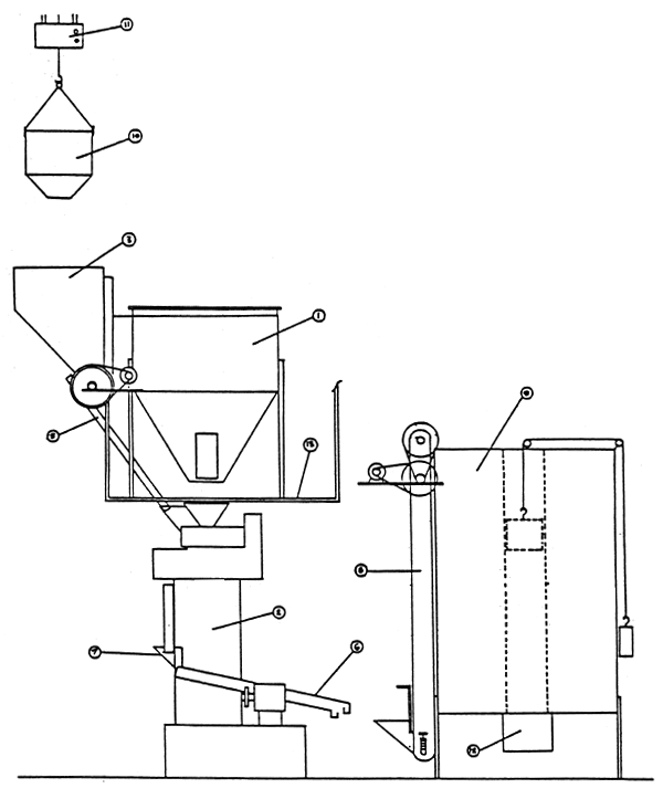
Legend
|
Figure 1. Present feedmill installation (side elevation)
For legend see Figure 1
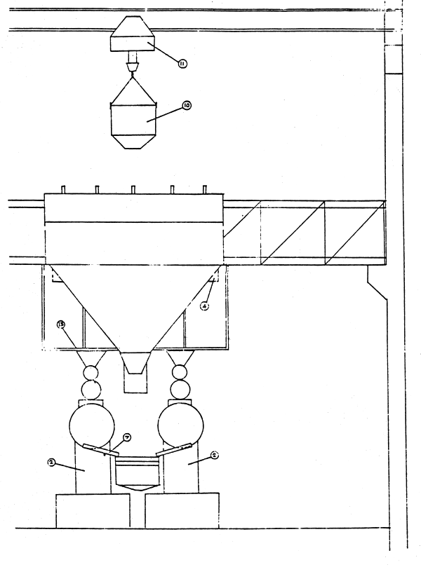
Figure 2. Present Feedmill (front elevation)
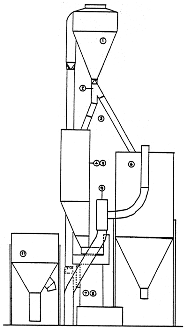 |
Legend |
| 1. Air cyclone 2. Distributor valve 3. Distributor valve (cyclone to bin) 4. Meal bin 5. Meal bin 6. Cooler/dryer 7. Pelleting machine 8. Pelleting machine 9. Fan for air lift 10. Air lift pipe 10a. Venturi intake valve 11. Vertical mixer |
Figure 3. Proposed modification A (side elevation)
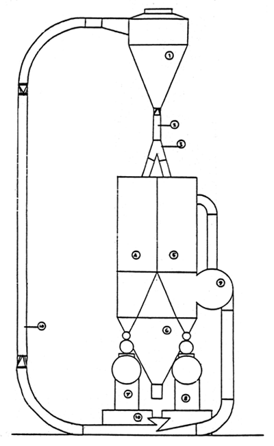 |
Legend |
| 1. Air cyclone 2. Distributor valve (cyclone to cooler) 3. Distributor valve (cyclone to bin) 4. Meal bin 5. Meal bin 6. Cooler/dryer 7. Pelleting machine 8. Pelleting machine 9. Fan for air lift 10. Air lift pipe 10a. Venturi intake valve 11. Vertical mixer |
Figure 4. Proposed modification A (front elevation)
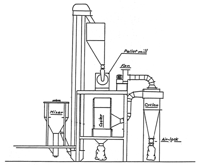
Figure 5. Proposed modification B
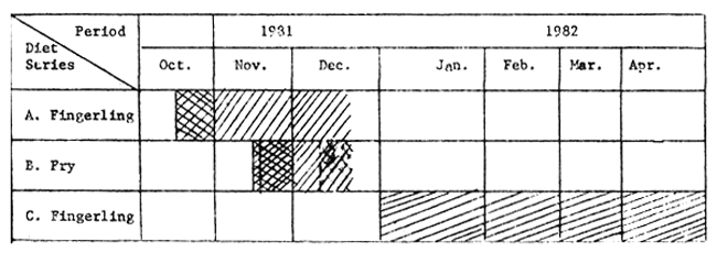
3×3 factorial; 9 diets; 3 replicates of 100 fish (average 10 cm) per pool; total: 2 700 fish
2 × 2 factorial; 4 diets; 3 replicates of 200 fish (average 5 cm) per pool; total: 2 400 fish
Select best 2 of 4 fry diets from B; factor fish on these into 2 best of the 9 given diets from A; 2×2 factorial; 4 diets; 3 replicates of 100 fish per pool; total: 1 200 fish.
Figure 6. Work programme for development of diets for Clarias culture.

Figure 7. Work programme for development of diets for Macrobrachium culture.