The purpose of project programming is to have a clear flow on how the project will be implemented, the starting and completion time for a given amount of work, and labour force. This is done by estimating the amount of labour force available and their daily output in order to determine the number of days a piece of work can be finished.
The preparation of the development programme/schedule requires careful evaluation and realistic calculations that would result in an efficient and economical implementation of job activities. Probable constraints that would hamper the smooth implementation of the project should be anticipated and solutions presented.
In assessing the availability and quality of manpower in the vicinity of project site, considerations are given to the quantity and experience of skilled workers, time of availability (year round or seasonal), rate and condition of payment, and working arrangements prevailing in the locality.
In the event of manpower shortage, importation of workers from adjacent places becomes likely and the same assessment survey should be done.
As an example, the following is a simplified proposed programme of work for a 30-ha milkfish farm.
| Activities | Work arrangement | Daily labour requirement | Duration (days) | Equipment/Tools | |||
|---|---|---|---|---|---|---|---|
| 1. | Site clearing | Daily basis | 100 | 75 | 1. | Chain saw | |
| a) | Under brushing; removal of tree trunks and debris; | 2. | Bolo | ||||
| 3. | Ax | ||||||
| b) | Path of perimeter dike | 4. | Bamboo raft | ||||
| 2. | Construction of gates | Contract work | 45 | 130 | All tools provided by contractor, such as concrete mixer or mixing form, digging tools, boat, water container, carpentry tools, masonry tools, steel saw | ||
| a) | Construction of temporary dike | ||||||
| b) | Construction of foundation | ||||||
| - Gate site excavation; | |||||||
| - Bamboo piling, boulders and gravel filling | |||||||
| c) | Construction/installation of wooden forms and reinforcing bars | ||||||
| d) | Concreting | ||||||
| e) | Removal of forms, plastering, soil backfilling, removal of temporary dike | ||||||
| f) | Gate curing, conditioning and construction of screens | ||||||
| g) | Construction and installation of secondary and tertiary wooden or concrete gates and pipes | Daily basis | 30 | 30 | As in a-f and 3 | ||
| 3. | Earthwork (manual) | Daily basis | 150 | 160 | 1. | Digging blade | |
| a) | Construction of dikes | 2. | Flatboat | ||||
| b) | Construction of canals | 3. | Flashboard | ||||
| c) | Uprooting stumps | 4. | Stakes, plastic hose, side slope model | ||||
| d) | Levelling pond bottom (cut and fill) | ||||||
| 4. | Construction of caretaker's hut, storage and working shed, chilling tank | Contract work | 25 | 65 | 1. | Concrete mixer or mixing form | |
| 2. | Digging tools | ||||||
| 3. | Masonry tools | ||||||
| 4. | Plumbing tools | ||||||
| 5. | Road dike | Contract work | 4 | 20 | 1. | Dump truck | |
| 2. | Payloader | ||||||
| 3. | Grader | ||||||
Based on the programme of work, a schedule of construction activities is also prepared. Development schedule should consider nature of funding and time elements. If funding is obtained through loan from the bank, the time of payment for the interest should be included in the development strategy. Banks usually charge interest payment on fish farm development loan two years after the first release. It is likely that during the second year, production would not be enough to pay for the interest. Chances are that unforeseen shortage of workers exists during construction or there may be a delay in pond conditioning especially if it is acidic. Under this situation, pond development should proceed ensuring that: (i) the ponds are secured against flood and other destructive forces of nature; and (ii) it must produce at the start of the second year, enough to pay for the loan interest and other financial requirements. Thus, schedule of construction of pond compartments should be phased such that one or more rearing ponds are already complete and functional, so that by the end of the year, production can start while the other portions are still being completed.
An example of general development schedule for a 30-ha farm is as follows:
| Activities | Jan | Feb | Mar | Apr | May | Jun | Jul | Aug | Sep | Oct | Nov | Dec | |
|---|---|---|---|---|---|---|---|---|---|---|---|---|---|
| 1. | Preparation of feasibility study | xxxx | xx | ||||||||||
| 2. | Acquisition of bank loan | xxxx | xxxx | xxxx | |||||||||
| 3. | Relocation survey | xxx | |||||||||||
| 4. | Canvassing of materials and labourers | xxxx | |||||||||||
| 5. | Procurement and stock piling of materials | xx | xxxx | ||||||||||
| 6. | Construction of worker's temporary shelter | xxxx | |||||||||||
| 7. | Site clearing | xxxx | xxxxx | xx | |||||||||
| 8. | Establishment of markers | xx | |||||||||||
| 9. | Construction of main gate and temporary enclosure dike | xxxxx | xx | ||||||||||
| 10. | Construction of main dike | xxxxx | xxxx | xxxx | xxxxx | ||||||||
| 11. | Construction of partition dikes | xxxx | xxxx | xxxx | |||||||||
| 12. | Construction of secondary gates | xxxx | xxxx | xxxx | |||||||||
| 13. | Construction of tertiary gates | xxxx | |||||||||||
| 14. | Construction of supply canal | xxxx | xxxx | ||||||||||
| 15. | Pond excavation and levelling | xxxx | xxxx | xxxx | |||||||||
| 16. | Construction of caretaker's hut and storage shed | xxxx | xxxx | ||||||||||
| 17. | Road dike and others | xxxx | |||||||||||
The purchase and stockpiling of materials should also be accomplished according to the construction schedule. Costs should be weighed against availability and transport of materials under different climatic conditions. Some materials like gravel, sand, cement, lumber, and bamboo poles should be purchased and transported to the pond site during dry weather. Transporting them at this time is easier and cheaper. Bamboos have to be purchased during dry season to get good quality poles. Some equipment like the cement mixer, hollow blocks machines, vibrators, steel cutters, and water pumps should be acquired or leased at the proper time. All these will require a cash flow which should be indicated in the construction schedule.
Experience in Malaysia indicates that since water control structures are generally small and widely scattered over the pond site, it has been expensive to transport material and construction plant to the various locations. In many cases, transport cost of material have exceeded the actual cost of material itself (Khoo and Santhanaraj, 1982).
Initial clearing begins where the main dike and main gate are to be located. Full scale clearing then continues as the construction of main dike and main gate proceeds. The entire area of the fishpond site should be cleared of all grasses, trees, roots and stumps. All cleared materials should be thoroughly removed from the site of work.
Site clearing can be accomplished by any or combination of the following methods:
Underbrushing. In underbrushing, vegetation including nipa trees and shrubs, of less than 10 cm in diameter are cut with the use of bolo. This operation must be done systematically in blocks and be completed immediately before the perimeter dike and the main gate are completed. This is to prepare the pond for the next process. Underbrushing is done by manual labour and the work begins as soon as the foundations of the main dike and the main gate have been established.
Withering (Optional). Withering is to kill the trees by filling up the pond with water. It has been found that mangrove trees, specially the group of Rhizophora, usually die out when their trunks are constantly soaked with water at a depth of more than 0.5 m for a period of 4 to 6 months. The fallen leaves serve as fertilizer.
Falling. Falling is simply cutting down big trees left after underbrushing. The falling operation should commence when the tree bark begins to peel, but before the leaves and branches fall. The prerequisite of falling is to dry and harden the ground, which can be done by keeping the water table of the entire pond area at 0.3 to 0.5 m below the surface for a period of 1 to 3 months, depending on the weather conditions. Either manual or mechanical method, or a combination of both, can be employed for falling. A chain saw is effective in falling big trees and cutting logs. It is a fast method and economical to use.
Uprooting of stumps. Complete removal of tree stumps and root system embedded in the soil is done by manual labour or by the use of small machines. Manual labour is effective and economical in areas having small stumps and roots, but for big stumps and larger areas, it is more economical to use a winch and pulley block (Fig. 6.1) or a mechanical tree puller (Fig. 6.2).
The mechanical puller consists of a winch and its accessories. The winch is powered by 8 to 16 Hp gasoline engine for lightness and portability. The winch and the engine are set on a common steel base provided with an anchor, holdfast or a log-deadman (Fig. 6.3). The steel cable, provided with a quick-detach shackle, is then tied securely to the stump. When the engine is started the winch will pull out the stump. For extra large trees, roots opposite the winch may have to be cut if the winch cannot pull the tree out entirely.
The mechanical puller is moved from place to place, until all the stumps have been uprooted. When pond is flooded with tide water, the uprooted stumps will partially float and can thus be removed from the pond.
(a) Digging blade. Manual construction of dike is usually done by piling soil blocks that have been cut by a digging blade. A soil block measures approximately 30 cm × 30 cm × 60 cm which is cut by a hand tool locally called “tagad” in the Philippines (Visayas) and “sarap” in Indonesia (Fig. 6.4). In Thailand, they also use this type of digging blade, with a slightly different construction. There are also other hand tools for digging soil found in the region and these are shown in Fig. 6.5.
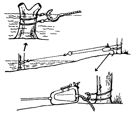
Fig.6.1 Sketch showing how to use a winch and a pulley block for manual destumping (After Maar and Mortimer, 1966)
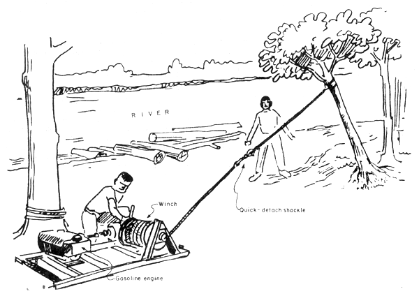
Fig.6.2 A mechanical tree puller (After Jamandre and Rabanal, 1966)
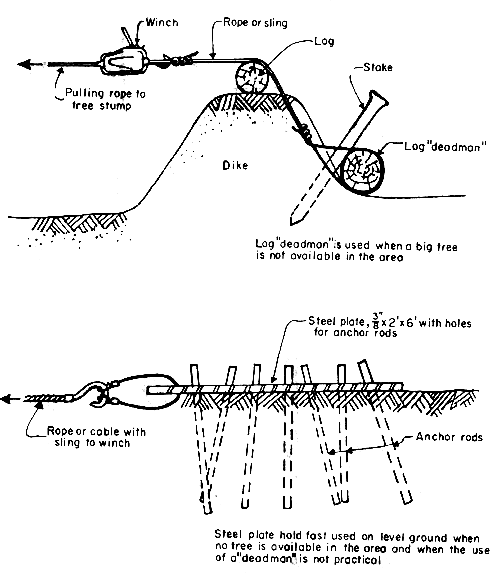
Fig.6.3 Types of anchor for manual destumping (After Hechanova and Tiensongrusmee, 1980)
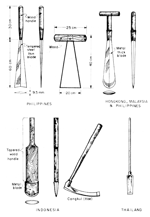
Fig. 6.4 Types of digging implements for fishpond construction
(After Jamandre and Rabanal, 1975)
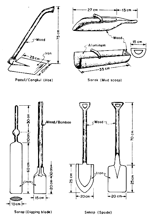
Fig. 6.5 Additional digging tools in Indonesia for fishpond construction and repairs (After Ranoemihardjo, 1982)
(b) Bamboo raft, dugout boat, flatboat. The soil blocks are transported from the digging site to the path of the dike by a bamboo raft, dugout boat or a flatboat. The bamboo raft, however (Fig. 6.6), has a much smaller load capacity than the flatboat (Fig. 6.7). The flatboat is presently considered the best method of hauling soil blocks because of the following advantages:
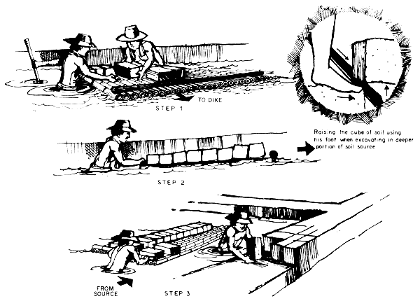
Fig.6.6 Bamboo raft for transporting soil blocks in diking
(After Denila, 1977)
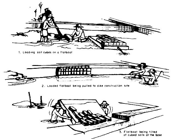
Fig. 6.7 Flatboat for transporting soil blocks (After Denila, 1977)
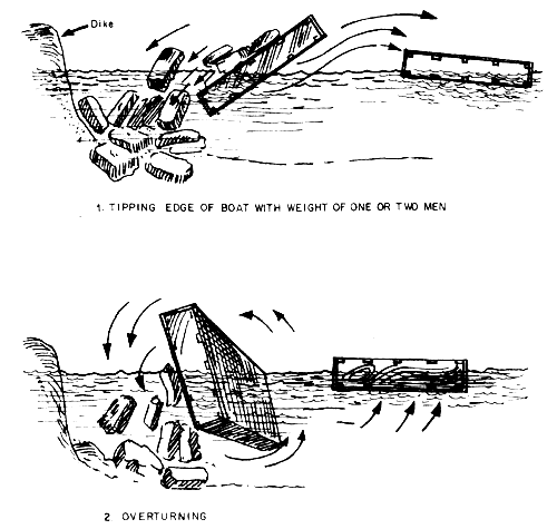
Fig. 6.8 Two ways of unloading flat boat (After Jamandre and Rabanal, 1975)
(c) Wooden mallet or tamping device. This tool is used to compact the soil blocks on top and sides of dikes. This is made of a short log about 30 cm long and 30 cm in diameter. The end that gets in contact with the soil is cut into a wedge of 45° angle and provided with a handle about 1.8 m long. The device is manually raised and made to fall against the dike surface repeatedly. Proper soil moisture condition is needed for using the mallet effectively.
(a) Dragline. Singapore and Malaysia generally use dragline. The operations consist of bringing to site a track-mounted crane. With the crane are many 0.1 × 0.3 × 4.0 to 5.0 m planks which are self-laid by the crane for its own base. As work progresses, the planks are self-shifted by the crane so that it is resting at all times on a series of platform planks preventing it from bogging down in mud.
This particular equipment is particularly good for dike construction, canal digging and deepening (Fig. 6.9). Hence, it is suited for excavating shrimp trapping ponds in order to have deeper water. However, it is not practical for large-scale within-compartment-levelling because of its being too slow and unwieldy. Its use is also limited where mass hauling of earth in some areas for dike building is involved. It is by design, an equipment for in-place working. There is now in the market a crane mounted on LGP (low ground pressure) tracks. This makes the crane more maneuverable in swampy areas and cuts its non-productive plank-transferring time by half. This crane can be equipped with clam shell buckets.
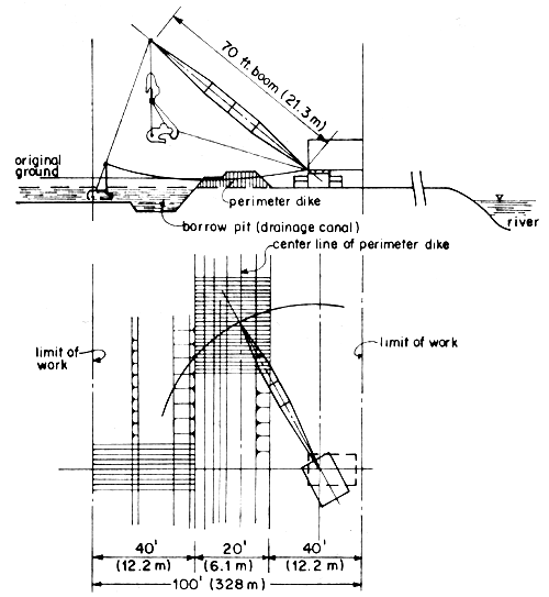
Fig. 6.9 Range diagram and limits of work of drag line as defined
for the construction of the perimeter dike
(After Hechanava and Tiensongrusmee, 1980)
The cost of using draglines vary with the kind of soil material and its size. The effective working range depends on the length of boom (Fig. 6.9).
(b) Dozer-crawlers (Fig. 6.10). This particular equipment is good for levelling provided the load-bearing capacity of the soil can support the equipment weight. Recent designs of these equipment are provided with mechanisms which improves speed and maneuverability, thus cutting down construction time. The effective working range of most dozers in dry soil conditions vary from 20 to 40 m.
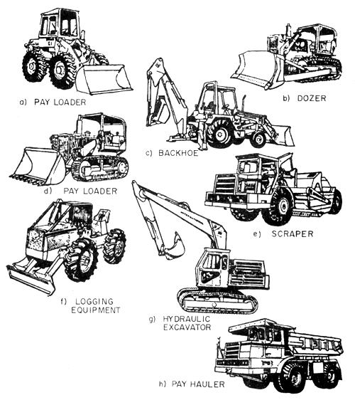
Fig. 6.10 Some heavy equipment for fish farm construction
(After Tarnchalanukit, 1982)
Most crawler manufacturers have now incorporated LGP tracks to their line of crawlers to enable it to work on wet soils. On LGP, the ground pressure usually is around 0.28 kg/cm2. The LGP crawlers come in a variety of sizes, ranging from 20 to 200 BHp. One has therefore a good choice to suit the area to be developed or the transport situation to the work area. In some instances, small LGP dozers are chosen over a large one for convenience in transporting the equipment to the job site by raft or passing on bridges which have limited load capacity.
(c) Hydraulic excavators, backhoe, shovels, cranes, pay loaders (Fig. 6.10). These are equipment that can also be used to advantage in fishpond projects. One advantage the hydraulic equipment have over cable cranes are their fast action and flexibility to adapt to a variety of situations. These can also be adapted with clam shells and grapplers and can be used for uprooting small tree stumps.
(d) Scrapers, dump trucks, wheel-type loaders (Fig. 6.10). These may also be used effectively where soil conditions permit.
(e) Suggestions on mechanization. Much waste has been observed in the use of mechanized equipment. In order to be able to adopt this method with success, one must know the following: (i) capacity; (ii) limitations; (iii) limit of maximum operating range; (iv) ground pressure; (v) working conditions; (vi) amount of work to be done; (vii) type of work required; and (viii) cost per unit of work accomplished.
There are equipment now especially fabricated for reclamation and swamp work. These types can be used in mangroves effectively. However, one should be conversant with the different types of equipment and be able to judge critically the type of equipment needed after seeing the project area. There are some large equipment which can be taken apart into several components and reassembled at job-site. Some cranes and hydraulic lifters are also designed to be barge-mounted with their tracks on while on the shore.
In addition, the economical or effective range of the equipment should also be known. At what distance should one consider a loader and a dump truck combination over a crawler? It would be uneconomical beyond about 35 m due to its track wear and long cycle time. Beyond 35 m on volume of soil movement, one might want to employ combination pay loaders with several dump trucks. The economics of this operation should be worked out. Scrapers (self-loading and crawler-assisted) are ideal for large projects. Dredges can be used effectively too. Under special situations, jetting pumps can effectively facilitate uprooting of stumps. All of the above require a thorough knowledge of the project site peculiarities as well as the different equipment available, their specifications, capacities and limitations. An expert's advise in this field is usually necessary.
The main gate is constructed ahead of the main or perimeter dike to allow time for curing of concrete and have it used while the main dike is being completed. All the materials needed should be in the site prior to construction.
During construction, the design specifications must be followed particularly in the construction of gate foundation; the provisions against undercutting of water, the spacing and size of reinforcements against side and bottom pressures; and the proper mixture and curing of the concrete or brick (hollow block).
Construction begins by preparing the site. The exact location is measured and staked out. Enough working space of 1 to 2 m around the gate foundation should be provided.
A reference point for checking the elevations of gate flooring, heights, soil excavations and others must be established.
A temporary but strong dike capable of withstanding tidal water pressure must be constructed to enclose the site and working space. Entrapped water inside the site is removed manually or by pumping.
(a) The gate foundation. Construction is guided by following either of the two illustrations in Figures 5.10 and 5.11. In Figure 5.10, the site is excavated to 0.6 m deep from the reference point. Removal of roots, stumps and mud or soft soil is done, if any. Excavation should include the portion where the toes of the gate will be constructed. Excavation is done manually or by dragline or a backhoe on tracks in mechanized construction.
The spacing and lengths of bamboo base, mangrove or wooden piles that support the structure should be observed. A common practice by fish farmers is to drive two lengths of piles vertically: the 3-m length is driven at one-meter interval while the shorter (one to two-meter) length is driven 25 to 30 cm apart within the longer piles. Leave at least 25 cm of the pile head above the soil surface. This exposed ends should be in level.
In some designs, wooden planks with pointed ends measuring 5 cm × 15 cm × 180 cm are also used in addition to bamboo piles. These planks are driven side by side along the centreline of side and wing walls and both ends of aprons. These planks extend the depth of concrete cut-off or toe walls and further help in preventing undercutting of water.
Boulders are laid about 20 cm thick between the piling to form a floor. Gravel layer of 5 cm thick is spread on top of the boulders, and then compacted. The exposed ends of the piles should be level with the surface of the gravel layer.
(b) Forms and reinforcing bars. After the foundation, the forms for the slab or flooring and toes are constructed. The reinforcing bars are laid as per plan. The elevation of flooring should be checked if still within the prescribed value.
Initial pouring of mixed concrete along the footing is done to keep in place the vertical reinforcements for side and wing walls including collars. Then the horizontal bars are tied with No. 16 wires with the vertical bars as per plan. In addition, reinforcements for catwalk or bridges are also installed. While installing the reinforcements, the forms for walls, bridges and collars are being prepared.
The forms are properly set and should be rigid to stand the weight of poured concrete and to avoid bulging of sides. The reinforcement bars should be centred within the forms. The forms are spaced apart to have a finished concrete wall of at least 15 cm.
(c) Concrete mixture, pouring and curing. Concrete mixture should be in proportion of 1:2.4 (cement:sand:gravel) for all concrete works. If concrete hollow blocks are used (for small main and secondary gates), the mixture should be 1:7 (cement:sand).
Prior to pouring of concrete mixture, the water that have seeped into the gate construction site should be drained out. Then pouring of mixture follows continuously until completed. During pouring, concrete vibrator or a piece of iron or firm wood should be used to compact the mixture to prevent hollow or void spaces and to insure smooth concrete surface upon removal of the forms. Saltwater should not come in contact with the concrete while still wet.
Allow the concrete to set in and harden for 2 to 4 days before removing the forms. Plastering the surface may be done as necessary. Plastering mortar of 1:3 (cement:sand) ratio should be applied at a thickness of 6 to 10 mm.
Soil backfilling of excavated areas is done to have a finished ground surface around the structure. Proper compaction between walls of the structure and adjacent soils should be observed.
Continuous curing of the concrete structure should be done for 28 days. Curing is done by covering it with jute sack or similar materials and sprinkling freshwater to make it moist throughout the day for the whole curing period.
The temporary dike may be removed after 30 days. Condition the structure by letting tidal water to come in and out of the gate.
Wooden gates have much shorter life span than concrete. This is preferred for reasons of economy or when initial capital is limited the use of wooden gate is resorted to until such time that the owner decides to replace it with concrete.
The parts, shape, height and inner dimensions of wooden gates are also similar with concrete. They are however, easier and faster to construct. Construction is carried out as follows:
The materials used are either regular lumber, stripped/ whole coconut or palm trunks and bamboo. These materials are selected for quality; they must be adequately shade dried for 2 to 3 weeks before construction.
The wood are planed to have smooth edge and surfaces. The materials are then cut as per plans and specifications of the gate. To prolong the life of the wood, thick coating of coal tar is applied. Creosote or other similar wood preservatives may also be applied. Some gate builders mix coal tar and cement and the mixture is painted in two coatings to the materials, then left under the sun for drying.
While drying the wood materials under the shade, the usual reference mark for checking the elevation of the gate should be established as well as preparation of the foundation.
The foundation may not be as strong as in concrete gate. Excavate the site according to desired elevation. Bamboo base or mangrove piles are driven to support the structure if needed (Figs. 6.11 and 6.12).
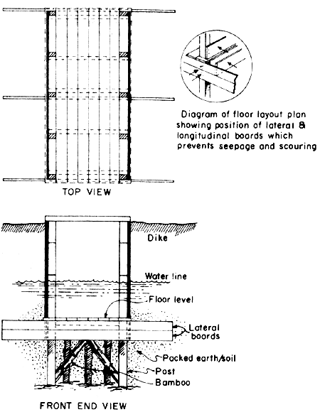
Fig. 6.11 Wooden gate construction
(No middle anti-seep board)
(After Jamandre and Rabanal, 1975)
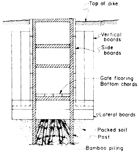
Fig. 6.12 Wooden gate frontal view, no wing wall but with anti-seep board (Modified after Jamandre and Rabanal, 1975)
The various parts of the gate such as the walls, flooring, cut-off walls, anti-seepboard (Fig. 6.12) are separately nailed to the respective braces, pillars or supports. This is done outside the site. The component units (side walls, flooring, cut-off wall, etc.) are then assembled together by using galvanized nails, or bronze nails, if available, to form the gate after the preparation of the foundation (Figs. 6.11 to 6.13). In some cases, the whole gate unit is already assembled outside the site and just lifted and placed properly on top of the site, but sometimes the the finished gate is quite heavy.
The walls and flooring of the gate are tightly nailed side by side. Water tightness improves the moment the wood is soaked in water and expands. However, there are also water sealant compounds that further insure water tightness.
In Indonesia, some secondary gates are designed and constructed without nailing the flooring, the side and wing walls. The wallings are vertically piled one on top of the other and tightly sandwiched between the vertical supports or pillars and the dike soil. Even the cleats or grooves for the screens are not nailed permanently. The major advantage of this design is convenience in repair or replacement of decayed wood member. The member to be replaced is just pulled out easily and then the replacement is immediately inserted.
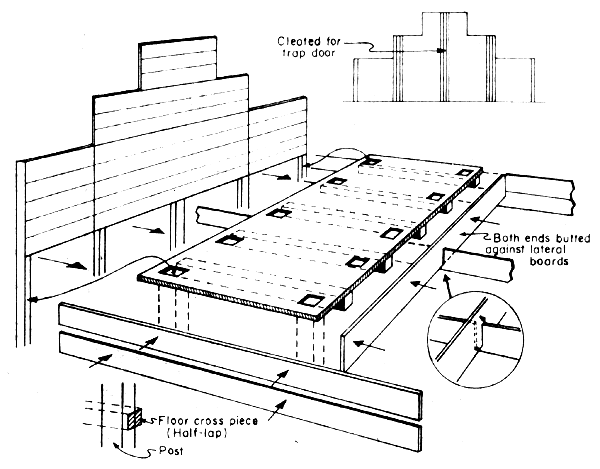
Fig. 6.13 Wooden gate construction, preferably preservative-treated wood
and copper or galvanized iron nails
(After Jamandre and Rabanal, 1975)
After installing the gate, the space between the excavations and walls are mud-packed by soil blocks arranged in layers. Then the soil is allowed to dry and harden.
Conditioning the gate is done by allowing tidal water in and out of the pond. Checking for seepage is also being done at this time.
The most important component of the fishpond system is the dike enclosing the entire pond area. The perimeter dike is the first dike to be constructed to free the area from the danger of floods. The utility of the pond system will depend on the strength and lifetime of the perimeter dike. Construction may be done by manual method with light implements and by using heavy equipment.
(a) Manual construction. Main dike passing across rivers, creeks and low areas should be constructed first. Construction should be done by arranging soil blocks properly in between staggeredly driven bamboo or mangrove piles as reinforcement. The arrangement of soil blocks and piles are shown in Figure 6.14.
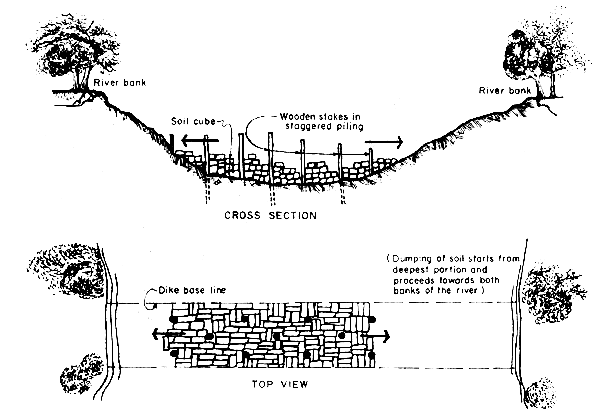
Fig. 6.14 Closing of river or creek (After Denila, 1977)
Note: This is not advisable but done only if necessary and possible
adverse effects compensated
As the first step, construction of all dikes is preceded by thorough clearing of the path of dikes and their immediate vicinity. The width of clearing is slightly wider than the base of the dike to be constructed. Trees, roots, stumps and undecomposed organic matter should be removed out of these path. Clearing is guided by staking out the centreline of the dike. After the clearing, the base and top width of the dike are properly marked with stakes on the ground. Construction of the core or puddle trench along the main dike follows in order to provide a good key between the dike soil and the foundation as well as minimizing seepage through the dike. The puddle trench is constructed by excavating a trench measuring at least 0.5 m wide by 0.5–1.0 m deep along the centre path of the main dike. The excavated trench is then backfilled to the same ground level with a new soil which is wet enough to be puddled by feet or compacted by a wooden mallet or tamping device. The importance of puddle trench is well recognized but sparingly practiced probably due to the added cost. Although costly, it cuts a lot of water management problems in the future.
Construction of main dike proper follows. The stakes set for the size of dike guide the proper arrangement or piling of soil blocks which are taken from higher grounds and are being transported by flatboats or rafts. Other methods of transporting soil blocks are by the line system and sliding system. In the line system, workers form a single line (Fig. 6.15). Each worker is positioned at 1 to 2 m apart. The line extends from the source of soil to the dike construction site. Soil blocks are relayed to each man until it reaches the piler. The sliding system applies when the source of blocks is close to the site (Fig. 6.16). The worker throws the block on the board letting the soil slide down to the base of the dike. Among these methods, the use of flatboat is considered the best.
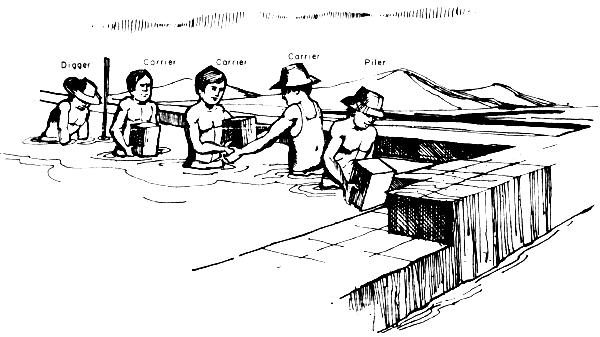
Fig. 6.15 Five workers working in group in pond with water
(After Denila, 1977)
The piler of blocks sees to it that they are tightly placed end to end. Compacting each layer of soil blocks by feet or tamping device is recommended. The proper placement of soil are shown in Figure 6.17. The recommended finished form of dike is shown in Figure 6.18.
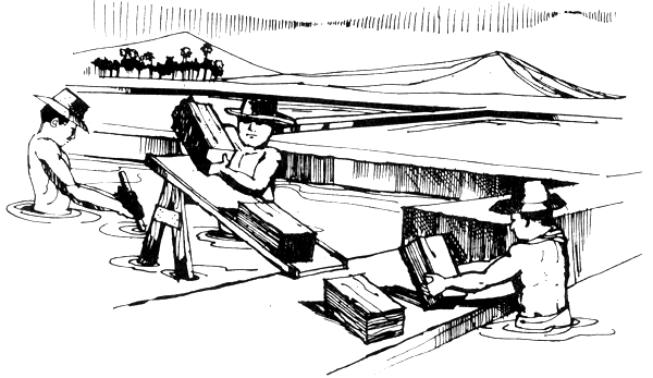
Fig. 6.16 The sliding board method of moving soil blocks (After Denila, 1977)
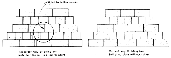
Fig. 6.17 Proper way of piling soil blocks for dike (After Denila, 1977)
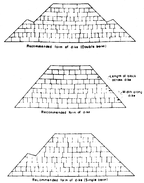
Fig 6.18 Arrangement of soil blocks and proper form of dike in manual method of construction (After Denila, 1977)
The proper side slope must also be observed in the piling of blocks. The base and top width stakes as well as a side slope model (Fig. 6.19) serves as guide in checking the correctness of side slope.
The height or elevation of the top of dike should also be checked, if done according to specifications. It is important to have uniform elevation of top of dike in every compartment. To accurately measure this, a 12-mm transparent plastic hose, 25 to 30 m long is filled with water. One end is held by a man at the starting point while the other end is held by another man. The water level at the two ends of the hose must be the same. This level is properly marked and is checked against the finished elevation of the top of dike. The same procedure is done in subsequent stretch or station of 20 to 25 m until the entire length of dike is covered.
The plastic hose with water is also used in laying out the bed slope of canals of a fish farm.
(b) Team work versus individual work in dike construction. Some construction workers group themselves as a team in working. The team is usually composed of four members. each with distinct functions — the soil piler, the soil block digger, raft or flatboat pusher, and the carrier. The carrier receives the soil blocks transported and unloaded by the boat pusher at the site, and passes them to the piler.
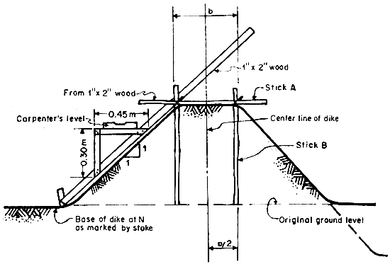
Fig. 6.19 Side slope model made for dike slope of 1:1
(After Hechanova and Tiensongrusmee, 1980)
Other workers prefer to work individually. Each worker is provided with flatboat and does the digging, transporting and piling (Fig. 6.20).
It is claimed that one skilled worker with flatboat can finish a dike with size of 6 to 7 cu.m in 8 to 9 hours, compared to 3.5 cu.m only for each member in the team work (Denila, 1977).
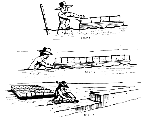
Fig. 6.20 One man - one flat boat operation (After Denila, 1977)
Construction of secondary and tertiary dikes follows the same procedure as in construction of perimeter dikes. Puddle trench is also recommended to be included in the construction. The dikes may have berm to accommodate excess soil from the pond and to decrease soil erosion and water turbidity after a heavy rainfall. This berm is also a good working space during repair of dike leaks or seepage rather than doing repairs by staying on the crown.
Water canals are constructed following the same procedure as in dike construction. Canal bottom is, however, excavated deeper than the pond bottom and secondary gates if the channel or canal is purposely designed for filling and draining the fishpond.
Pond levelling is the final step in fishpond construction. Some operators pay little attention to pond levelling and think that construction of fishpond is finished after the main and the secondary dikes have been constructed. One of the major reasons for low pond productivity is due to rough or poorly levelled pond bottom.
Levelling the pond just after the dikes are constructed is quite expensive. It is advisable to wait for two to three years until the root systems of the trees have partially decayed before levelling is started. This will lessen the capital outlay. Partial levelling may be done just after enclosure, but excavation should be limited only to portions where there are no trees. The soil excavated should be dump in low portions that cannot be drained. After two to three years, final levelling can be completed.
After a topographic survey has been made, the pond bottom elevations should be determined. Likewise, the volume of soil to be cut and the portions to be filled should be marked out by stakes. In the Philippines, a simple method of pond levelling is done by using the tidal water. The procedure for this is as follows:
Bring the water down to the desired pond elevation and place a bench mark to identify it (Fig. 6.21). Beside the bench mark, place another stake about 7.5 cm wide, 2.5 cm thick and 2 m long, marked from 0 to 100 cm (Fig. 6.22). The zero mark of the gauge should be level with the bench mark. The gauge indicates the depth of water and serves as a levelling guide during filling of low spots and in cutting soil from high places.

Fig. 6.21 Illustration of procedure in determining depth of soil above O tidal datum using water level, staff gauge and depth gauge
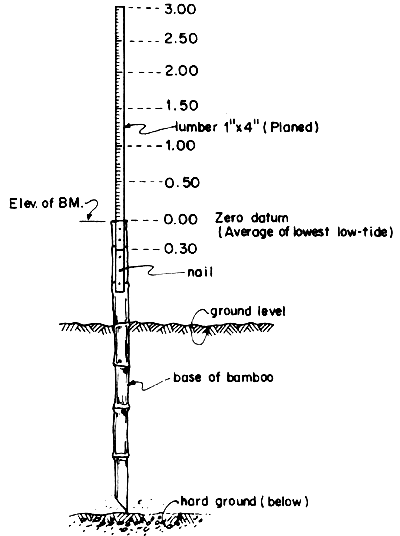
Fig. 6.22 Staff gauge as benchmark
(After delos Santos, 1980)
Establish stations by marking principal locations of high grounds or above the zero elevation mark as well as the low areas to be filled.
Allow water in to a depth of about 30 cm so that the flatboats are afloat and start excavation. All vegetative cover is stripped and loaded to the flatboats and dumped outside the pond. The standard length for one handle length of the digging blade is 30 cm so that if the handle is placed in the water and the ground level is 15 cm above the zero mark, 50 percent of the handle length should be excavated. In areas of extensive excavation, the soil can be loaded directly on flatboats and placed in the dikes, in low spots or areas that are below zero elevation. The remaining soil on either side can be levelled easily using spades (Fig. 6.23). One to two workers should be at the receiving end to supervise the dumping of soil in the deep portions. The receivers check the depths by a depth gauge (Fig. 6.24). Each receiver can supervise 20 flatboats.
When all marked portions have been excavated, bring down the water to 0 elevation. With the use of a spade the final levelling can be done.
The process is repeated for other stations or locations until all other low portions are filled.
During the final levelling, with the water at elevation 0, all water pockets should be connected by small canals.
In levelling work consisting of excavations and filling of low areas, a worker can have a finished job output as follows:
| Working range (from excavation to filling area) (m) | Levelled/filled area (m2) | |
|---|---|---|
| (a) | 10–100 | 40–50 |
| (b) | 101–300 | 30–40 |
| (c) | 301–500 | 20–30 |
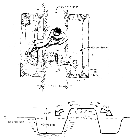
Fig. 6.23 Stripping method of levelling (Cut and fill)
(After Jamandre and Rabanal, 1975)
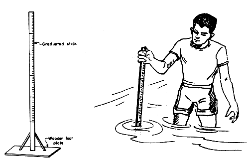
Fig. 6.24 A simple depth gauge (After Jamandre and Rabanal, 1975)