2.4 Devices and instruments for measuring sediments
A great number of apparatus and instruments have been developed in attempting to measure each process of the erosion-sediment transport sequence. However, at present, none has proved to be fully satisfactory, reliable and free from disturbing secondary phenomena. Some critical interpretation of the sample analysis by a specialist is always desirable.
2.4.1 Total collection tanks
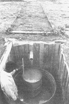
A total collection tank (Fig. II-1) may be constructed to measure erosion in small test plots. The collection tank should be large enough to contain the total runoff (water and sediment) expected in a 24- or 48-hour period. The volume of the water-sediment mixture is then determined and the solid sediment material sampled for subsequent laboratory analysis and computation of its weight and volume.
Total collection devices are often unsuitable because runoff storage requirements may be excessive. Also, very small drainage areas are generally not representative of field conditions.
2.4.2 Slot samplers
To remediate the drawbacks of total collection tanks, slot samplers, which collect a predetermined percentage of the runoff-sediment mixture, are preferred because they can be used for larger test plots. The sampled volume of water-sediment mixture is then reduced to manageable quantities.
Slot samplers can be used for any erosion studies from small test plots to actual watersheds of several km2. These samplers are automatic and no observer is required during the sampling operation. Furthermore, sampling can continue under heavy runoff events.
The two main types of slot samplers are the stationary multislot divisor and the Coshocton wheel sampler equipped with a revolving slot.
Multislot divisor (Fig. II-2): Runoff is routed from the collector through a conveyance channel to a sludge tank where the heavier sediment particles are deposited. Overflow from the sludge tank is then routed through the multislot divisor where a sample is obtained from a single slot and routed to a sample storage tank. A second or third sample storage tank may be connected to the first, if additional sample storage is needed.
The Coshocton-type runoff sampler (Fig. II-3) collects and concentrates runoff from an erosion test plot or a natural watershed into a collector at the plot end from which it flows into an approach channel. Water discharge from this channel falls on a- water wheel, which is inclined slightly therefore causing the wheel to rotate. An elevated sampling slot mounted on the wheel extracts a sample of water-sediment mixture with the representative proportion.
2.4.3 Suspended sediment samplers
Several types of samplers of suspended-sediment have been developed such as trap samplers, direct pumping, integrating samplers, etc. However, only few of them are designed so that the intake velocity into the sampler is equal to the actual stream velocity. This characteristic is essential for the samples to be representative of the suspended-sediment concentration of the stream at the point of measurement. A well-designed sampler faces the approaching flow and its intake extends upstream from the zone of disturbance caused by the presence of the sampler itself.
Instantaneous samples are usually taken by trap samplers consisting of a piece of horizontal cylinder equipped with end valves which can be closed suddenly to trap a sample at any desired time and depth.
The pumping sampler (Fig. II-4) sucks water-sediment mixture through a pipe or hose, the intake of which is placed at the sampling point. Regulating the intake water velocity in order to be equal of that of the stream, the operator can obtain a sample that is representative of the sediment concentration at the point of measurement.
The integrating sampler (Fig. II-5) consists of a metallic streamlined body equipped with tail fins to orient it in the flow. An intake nozzle of an appropriate diameter projects into the current from the sampler head. An exhaust tube, pointing downstream, permits the escape of air from the container which is located in the sampler body. Valve mechanisms enclosed in the head are electrically operated by the observer to start and stop the sampling process.
A new method of in situ determination of suspended-sediment concentration is the application of optical, ultra-sonic or nuclear gauges (Fig. II-6). The working principle of these instruments is that a beam of light, x-ray, ultrasound or nuclear radiation emitted by a source with constant intensity is scattered and/or absorbed by the suspended-sediment particles. The decrease of intensity of the beam measured by an appropriate detector or sensor situated at constant distance from the source, is proportional to the sediment concentration, provided other relevant characteristics of water and sediment (chemical, mineral composition, etc.) remain unchanged.
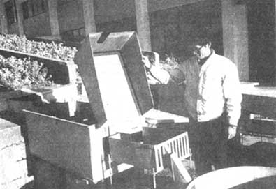
The automatic suspended sediment sampler is a system which automatically pumps up water and sediment samples from flowing water, storing up to 24 individual samples. The sampler can be used for routine monitoring and for recording the variation of sediment loads during transient floods.
Manual collection of suspended sediment samples can be a labour intensive and often unreliable method of obtaining data for sediment transport studies, so that automatic suspended sediment samplers are particularly suited for remote sites, or where there is a shortage of trained staff. The automatic sediment sampler can pump sediment suspensions through pipe lengths of up to 10m from flowing water, without altering the sediment concentrations or particle size distributions. It has a variable sampling time, intervals ranging from one a minute to one a day. The sampling schedule can also be programmed to trigger on rising water level for recording during transient floods.
Automatic sediment samplers have been used to monitor soil erosion from small catchments for studies of canal sedimentation, by taking regular daily samples from different depths so that the total sediment load can be calculated.
The single stage suspended sediment sampler (Fig. II-7) operates on the siphon principle. It is used to automatically collect suspended sediment samples from flash floods in intermittent streams at remote locations. The sampler consists of a bottle or other suitable container with about Ø 5 mm copper tubes that are formed to a siphon shape and inserted through taps which fit tightly into the tops of the bottles. Several samplers are mounted at various depths on a support that is fixed on the side of the stream so that samples are obtained at several water surface elevations as the water level of the stream rises.
Field experience suggests that sediment concentration obtained with this type of sampler may not be closely representative of that of the stream as the sample is always taken near the water surface during the rising stage, and the original sample may be altered by subsequent submerging. Intake velocities may not be the same as streamflow velocities. Because of these drawbacks, concentration data obtained with these samplers should be used with caution.
2.4.4 Samplers for bed-material discharge
Field measurement of bed-material discharge is difficult due to the erratic sediment movement which takes place in the form of moving ripples, dunes, bars, etc. No instruments have proved to be reliable for trapping the large and small sediment particles with the same efficiency, while remaining in a stable and flow-oriented position on the streambed and not altering the natural flow pattern and sediment movement.
Because of several uncertainties involved in sampling bed-material discharge, it is necessary to determine an efficiency coefficient for each type of sampler. The calibration takes place generally in a laboratory flume, where the bed-material discharge can be directly measured in a sump at the end of the flume, although uniform transport conditions over the width and length of the flume are difficult to maintain. Even under favourable conditions, efficiency factors are not easily determined because they vary according to the grain-size composition of the bed material, the degree of fullness of the sampler, etc. In any case, an efficiency greater than 60 to 70 percent can be regarded as satisfactory.
Available samplers can be classified into three types: basket, pan and pressure-difference.
Basket-type samplers (Fig. II-8) are generally made of mesh material with an opening on the upstream end, through which the water-sediment mixture passes. The mesh should pass the suspended material, but retain the sediment moving along the bed.
Pan-type samplers are usually wedge-shaped in longitudinal section and are located so that the point of the wedge cuts the current. The pan contains baffles and slots to catch the moving material.
Pressure-difference type samplers (Fig. II-9) are designed to produce a pressure drop at the exit of the sampler, sufficient to overcome energy losses, to ensure an entrance velocity equal to that of the undisturbed stream. A perforated diaphragm with a sampler body forces the flow to drop its sediment into the retaining chamber and to leave through the upper exit.
Bed-material discharge is determined from the amount of sediment trapped per unit time in a sampler located at one or more points on the streambed. There should generally be three to ten measurement points in a cross-section. In determining the distribution of sampling points, it has been noted that, except during flood periods, bed-material transport takes place in a portion of the stream width only.
A continuous record of bed-material discharge can be obtained by relating bed-material discharge to stream discharge. Considering the difficulties and shortcomings of the bed-material discharge measurement, computation by relationships based on theory and experiment are frequently used to supplement or control actual measured data, at least to ascertain their order of agreement. In the majority of rivers, the share of suspended sediment is predominant in the total sediment discharge. The percentage of bed-material compared to suspended material discharge is commonly assumed to be about 15 percent.
A rather new and indirect method for determining the bed-material transport is performed with the help of acoustic detectors. Submerged to the vicinity of the bed, these detectors pick up the "clicking" sound of moving gravel, indicating the movement of bed material at this particular point. Moreover, the intensity of sound and that of sediment transport may be qualitatively correlated with the size of the particles and their velocity.
Note: The source for Figures II-1, II-2, II-3, II-4, II-5, II-7, II-8, and II-9 is Hudson, N.W.: Field measurement of soil erosion and runoff. FAO Soils Bulletin 68, Food and Agriculture Organization of the United Nations, Rome, 1993. For the Figure II-6, the source is Crickmore, M.J., Tazioli, G.S., Appleby, P.G., Oldfield, F.: The use of nuclear techniques in sediment transport and sedimentation problems. Technical Documents in Hydrology. UNESCO, Paris, 1990.
Figure II-1. Total collection tanks
Figure II-2. Multislot divisor
Figure II-3. Coshocton runoff sampler
Figure II-4. Pumping sampler
Figure II-5. Integrating sampler
Figure II-6. Suspended sediment nuclear gauge
Figure II-7. Single stage suspended sediment sampler
Figure II-8. Bedload sampler
Figure II-9. Bed-material pressure-difference sampler
3.1 Introduction
3.2 Recommended measuring design
3.3 Instrumental equipment
3.4 Setting up of measuring stations
3.5 Field visits
3.6 Laboratory work
This chapter is devoted to the description of the characteristics of the measurement programme selected for the development of the Project, including not only the instruments needed, but also practical information of how to perform the setting up, the maintenance and the retrieval of information from it.
3.1.1 Design
The Programme is designed taking into account the hydrological and geoecological characteristics of Mediterranean coastal areas, especially:
• The small extent of uniform geoecological units, induced by the high diversity of the geology and topography (steep gradients and contrasted microclimates following aspect) in spite of the low altitude.
• The long history of human land use (degraded vegetation, modified microtopography, man-induced gully systems).
• The occurrence of short intense rainfall events, that can be preceded and followed by long drought periods.
The instrument design is fitted to the measurement of suspended sediment yield, or the particulate sediment fraction smaller than 2 mm. This fraction usually represents the main part of the total sediment yielded by small basins, with relative contributions higher than 80%, and is also the fraction linked to the loss of soil physical and chemical fertility as well as the water quality deterioration (Gregory & Walling, 1973; Hadley & Walling, 1984; Walling, 1988). Nevertheless, the sediment yields from some particular Mediterranean environments, like weathered granitic areas, would fail to be adequately measured by this design.
There are two main aspects to be taken into account about bedload transport by streams:
• The origin of bedload sediments is not usually the same as the source of fine materials. Stream bank erosion instead of soil erosion provides most of the coarse sediments.
• Measuring bedload transport is even more intricate than measuring suspended discharge; it needs comparatively expensive installations that are to be cleaned and maintained after every event.
If there is field evidence of a significant importance of bedload transport, a complementary measuring design should be implemented.
3.1.2 Technology
It is worth stating that, after the experience obtained during the development of the Pilot Project, it was agreed that the best choice would be to base the measuring instruments on the state-of-the-art electronic digital technology. The inconveniences of this choice are mainly related to the presumed lack of experience of the personnel, but this is overcome by the advantages of major autonomy and temporal resolution of the instruments as well as by the immense saving of labour with the use of computerized data management, compared with the traditional hand-based data analysis.
3.1.3 Duration
A measurement Programme devoted to the acquisition of quantitative reliable estimates of erosion and sediment transport rates would need to be designed for a very long period, due to the requirement to sample events of high magnitude and low frequency. Nevertheless, as the main purpose of the Programme is directed towards obtaining a scientific basis for better land management rather than to absolute figures, it can be organized in two steps:
• An initial phase of up to 3 years, for selection of sites, acquisition of instruments and implementation of the whole measuring design. This phase needs a wide scientific support in order to secure the best further advantages of work and money investments.
• A regular programme of 3-4 years, that can be developed by trained technical staff, but needs also scientific support for the adequate interpretation of results and for monitoring the programme implementation.
This design should ensure the adequate sampling of a range of events that are to be used to understand the erosion and sediment transport processes in the area, useful for guiding management strategies. Long-term erosion and sediment transport rates could be obtained trough the extension of the measuring period or by modelling the magnitude-frequency relationships. l
3.2 Recommended measuring design
3.2.1 Size of catchments
The measuring programme is based on the monitoring of water and sediment fluxes in a set of_small-sized catchments (0.5 - 20 km2). This represents a compromise between a full hillslope approach (runoff plots) and a fully hydrological approach (medium or big-sized drainage basins).
Plot approaches are adequate to calibrate erosion models or to analyze the performance of agricultural or soil conservation practices, but they would be too expensive for obtaining representative information of the actual erosion rates in the study areas. Studies at the plot scale can afford relevant information on erosion processes that would be useful for understanding the behaviour of the systems, but it is very difficult to relate plot-scale erosion rates with sediment yields, mainly because most of the sediments eroded from plots are deposited before reaching the streams.
On the other hand, sediment transport in large drainage basins is only fairly or poorly related to hillslope processes, because of the role of the sediment conveyance discontinuities: a significant part of sediments coming from hillslopes is deposited in temporary or permanent sinks, whereas the drainage network itself becomes the main source of the transported sediments. Soil conservation strategies based on measurements of sediment yield from large catchments can therefore fail to reclaim the actual sediment sources (Walling, 1983).
3.2.2 Number and arrangement of catchments
A minimum of a group of three catchments of different sizes is recommended. The catchments should be adjacent, in order to keep comparable characteristics of climate and to allow comparisons at the event scale.
Within a geographically homogeneous area several catchments, each with strongly differentiated land use and/or erosion rates should be considered bearing in mind that the measuring operations provide general trends rather than specific features related to point phenomena.
In most conditions, some of the smaller catchments should be contained within the larger ones (nested structure). This design helps to understand the rules of scale change in sediment transport processes.
This nested structure is highly recommended in areas of high erosion rates, in order to analyze the discontinuities of sediment conveyance (sinks and sources) that could hide the actual erosion phenomena or could be engineered to enhance the natural controls for sediment management.
3.2.3 Geoecological characteristics of catchments
It is recommended to select the several basins as representatives of the main erosion problems in the area. The smaller catchments should be selected to represent rather homogeneous areas either of high or low erosion rates, whereas the wider catchments can include heterogeneous terrain to understand the behaviour of the whole system.
The results of the mapping programme should be used as an indicator for selecting basins in which erosion is to be measured. Nevertheless, it is not possible to obtain an exact match between the two procedures, mapping and measuring. Furthermore, it is important to consider that pure, isolated characteristics are impossible to sample at any scale; the response of catchments being always the result of their characteristics as a whole (size, form, topography, geology, soils, land use, ...).
Pairs of catchments having analogous characteristics (twin catchments) could be considered for instrumentation within an experimental scope. The method envisages a calibration period, to asses the performance of one catchment compared to the other, and an experimental period, when the hydrological and erosion results of land management practices performed in one of the catchments are assessed through comparison with the other catchment, which remains undisturbed as a reference. The measurement programme could be used as the calibration period, but it will be necessary to continue the measurements after it, during a supplementary measuring period (Toebes & Ouryvaev, 1970).
3.2.4 Selection of measuring points
The location of measuring stations should be selected taking into account the following criteria:
• Accessibility: In addition to the work needed to set up the instruments, several hundreds of visits to the measuring stations will be needed during the development of the Programme.
• Protection against natural hazards (wildfires, landslides) as well as robbery and vandalism.
• Hydraulic adequacy: It is necessary to avoid points where low flows are missed (thick alluvial fills) or where high flows bypass the station (diverting channels or floodplains). The stream reach should be selected as straight and of constant slope as possible. These conditions are to be especially fulfilled if the water balance is to be assessed.
• Stream floor and bank stability: Stream reaches susceptible to major changes due to scouring or deposition of bedload or bank erosion should be avoided.
The use or improvement of pre-existing gauging stations is highly desirable in order to take profit of pre-existing information (calibration data, long hydrological records), as well as to make use of customary maintenance schedules.
The measurements are obtained through continuous monitoring of water discharges, together with some instantaneous observations of sediment concentrations, through sampling. The instruments needed are therefore the automatic permanent instruments at the stations to measure runoff and to take samples, the portable instruments to maintain the permanent instruments and to perform runoff measurements as well as sampling during field visits, and, finally, the laboratory instruments needed for measuring the sediment concentrations in stream water samples.
3.3.1 Field instruments at the stations
• Runoff control: Some structure (concrete or steel made) or natural constriction of the stream channel that provides a unique relationship between stream discharge and water level. More details are given in the header 3.4.
• Data logger: An electronic instrument designed to read and store information, following a modifiable programme, with a minimum capacity of two counting channels (rainfall and sampling event marks) and one analogue channel (water level). The memory of the instrument should be sufficient to allow a one-month autonomy with a recording rate of 5 minute-step. It is recommended to use an instrument directly interrogatable by a portable computer, and to be low power consuming device, fed by alkaline batteries, with a typical life longer than 12 months. All the accessories needed to set up and download data from the data logger must be available (software, cables and interfaces). The internal clock of the data-logger should be set to the solar time, in order to avoid errors due to seasonal changes of country official times.
• Water level sensor: An electronic transducer that converts water level into an electrical signal. It is to be directly fed and read by the data logger itself without the need of other devices or interfaces. There are several kinds of transducers:
• Shaft encoders or potentiometers are electronic instruments connected to classical float-pulley mechanisms for measuring water levels at stilling wells.
• Capacitive water depth probes are electronic instruments which use the contrast of dielectric properties between air and water to measure water level. They are robust and need cleaning only for very dirty waters.
• Piezometric sensors are instruments which measure hydrostatic pressure differences produced by water columns. They are good performance and reasonably inexpensive devices. The main problem with these instruments is that they can malfunction or be damaged after long drought periods.
• Ultrasonic instruments measure water level at a distance. These instruments are the best suited for heavily sediment charged waters, as they do not need any stilling well, but they are somewhat more expensive and need much more electrical source power than the others.
A capacitive sensor is recommended if long dry periods are expected (small streams in semiarid conditions). The model of the sensor chosen must be selected to ensure that all the range of water heights expected are covered and to give readings with an adequate resolution.
• Sampling instrument: It is very important to bear in mind that temporal variations of sediment concentrations are very high in ephemeral streams that drain small catchments, and the sampling gaps or mistakes are the main source of errors, which can be by one order of magnitude (Walling, 1988). Because of the ephemeral characteristics of runoff in Mediterranean areas as well as the mistakes that can be introduced in the manual sampling procedures, either or both of two kinds of automatic sampling instruments are prescribed; the choice depends on the economical and security constraints:
• A programmable pumping water sampling instrument. It has to meet two requirements: to be triggered by the data logger itself or by a water level threshold triggering mechanism, and to be able to output signals to inform the data logger for recording the exact time of sampling.
If the instrument is controlled by a water level trigger, the sampling program should be a sequential time type (one sample every time span), the length of the time span being adapted to the expected duration of the event (and also to the size of the catchment).
If the sampling instrument is controlled by the data-logger itself, the programme of the sampler must be set to sequential flow type, and the data logger is to be programmed to output digital (pulse) information to the sampler according to the water levels recorded (intelligent sampling). Another possibility is to perform a flow-proportional sampling schedule; this would be the best solution for obtaining a representative sampling of the transported sediments, but the inconvenience is the loss of information about the processes during the events.
A small solar panel (250 mA) is necessary to ensure a sufficient charge level of batteries to actuate sampling without weekly maintenance.
• A siphon-based sampling device which takes water samples at several water surface elevations as the water stage rises. These instruments are inexpensive, almost free of maintenance, and provide sampling of the rising part of the hydrograph which is usually missed by automatic pumping devices or by manual sampling strategies.
This instrument consists of a series of bottles (12 units recommended), everyone of them connected to two pipes. The entrance pipe of every bottle has a bend with the form of a siphon, whose height is the main characteristic of this bottle because it controls the height of the surface of the water able to fill the bottle. The exhaust pipes enable air to escape from the bottles when these are filled, the height of their free edge has to be higher than the highest possible level of the water to avoid recirculation of water samples. Both openings (entrance and exhaust) have to be protected against the entrance of the insects with a 2 mm mesh net. (Brakensiek et al., 1979, Walling, 1988).
If possible, the entrance siphons have to be placed in the same vertical of the control where the water height is measured, to ensure that the discharges reached when the respective bottles are filled is known. If the height-discharge characteristic curve of the station is known, divide the highest discharge by the number of bottles, and calculate the height of everyone of the siphons for every equal increment of discharge; if this characteristic of the station is not known as yet, you can take equal increments of height. The easiest construction solution is to attach the entrance siphons to a wooden shaft, then to secure it in the control section. An 8 mm (or similar) inner diameter flexible tubing for entrance and a thinner one for exhaust are recommended. Five to ten cm are recommended as height difference between the opening and the highest siphon level, depending on the magnitude of the quick oscillations foreseen for the water level.
The bottles can be one litre plastic ones, numbered starting from the lowest entrance one, and placed in a cabinet protected against vandalism with a key. This cabinet is to be located as near as possible to the siphons, in a low position with the bottles placed more than 20 cm below their respective siphons, and protected against the main water flow. Supplementary bottles and lids are needed to transport the bottles to the laboratory.
For relatively wide and quiet flow stream reaches, it is necessary to know the relationship between the suspended sediment concentrations in the samples and the mean concentration of the whole flow (Thomas, 1977).
• Rainfall recording stations: A minimum of one rain recorder per hydrometric station is prescribed. These instruments consist of tipping bucket magnet-reed contact measuring devices, that can be connected to the same data-logger used for runoff measurements. A resolution of 0.2 mm of rainfall per tip is recommended.
3.3.2 Portable equipment
The enclosed list provides an example of the durable and consumable instruments that are needed to perform the maintaining and sampling visits to the instrumented sites:
• Field books, pencils, waterproof pens, permanent markers (filter pens);
• a collection of bottles with caps for transporting water samples, for every sampler;
• a cleaning flask with distilled water, a cleaning brush for flasks;
• a 10-12 litre bucket;
• a shovel, a basket;
• a 5 kg hand scale (coil type);
• a clock and a stopwatch;
• a kit of tools (screwdrivers, pliers, scissors, measuring tape, etc.);
• a multimeter (voltmeter - ampmeter ohmmeter):
• a thermometer for water temperatures;
• a 0.5 l plastic graduated cylinder;
• a depth integrating suspended sediment sampler with accessories (rod or cable, reel and crane);
• a portable computer (notebook) with batteries and a waterproof bag;
• cables with plugs or interfaces for connection with the data-logger;
• diskettes for backup copies;
• a current meter with accessories (rod) can be also necessary if the runoff control is not calibrated by design.
The performances of the portable computer must be adequate for handling the software and transmission connection needed by the data loggers (PC AT compatible are sufficient in most cases). Autonomy, weight, robustness and reliability are more important than display quality, speed, as well as memory and hard disk capacity, that are usually the main elements determining the cost.
3.3.3 Laboratory equipment
The laboratory facilities should be adequate for performing routine determinations for sediment concentration of water samples.
The minimal requisites for laboratory durable equipment and consumables are summarized in the enclosed list:
• a water filtering facility, composed by two flasks (input and output), a filter holder, and a vacuum device (electrical or manual), with rubber pipes;
• pincers for handling filters;
• a precision balance, with a resolution of 1 mg;
• an electric heating plate with thermostat;
• a thermometer for water;
• a water electrical conductivity meter (portable if possible);
• cellulose membrane filters (0.45µm pore-size);
• petri slides or containers for individual filters;
• glass 1 l bowls (salad-type), heat-resistant;
• 1 l graduated cylinder;
• cleaning flasks, cleaning brushes for flasks;
• distilled wafer diluted HCI