The chopper is mainly used for stalk forage, such as rice straw, wheat straw, maize stover and maize for ensiling. Straw choppers can be classified by size into small, medium and large. The small-size chopper is mainly adapted for chopping dry straw or silage on small-scale farms. The large chopper - also called a silage chopper - is mainly used for silage on cattle farms. The medium chopper is normally suited to cutting dry straw and silage, so it is called a straw-silage chopper.
Choppers can be divided into cylinder or flywheel types, according to the mode of cutting. Large- and medium-size choppers are generally flywheel types, to facilitate throwing silage, but the majority of small choppers are cylinder type. Large and medium choppers are usually equipped with road wheels for easy movement, while small-size choppers are normally stationary.
Cylinder choppers
There are many types of cylinder chopper. The 93ZT-100 chopper (Figure 6-11), made by Wulanhaote Livestock Machinery Factory in Inner Mongolia, is taken as an example to describe the structure of a chopper.
The machine consists primarily of mechanisms for feeding, chopping, and throwing, with a transmission, a clutch and a frame. The principles of operation are illustrated in Figure 6-12.
The main parts of the feed mechanism are a chain conveyor, pressing rollers, and upper and lower feed rollers. For the upper feed roller, springs are used for pressure, with a cross-groove shaft coupled with a compact structure for driving. The chopping and throwing mechanism is in one unit, which consists of a main shaft, a blade rotor, rotating blades, a throwing vane and stationary blades. Gear teeth are 13, 22, 65 or 56. By changing the gear used, the speed can be adjusted to obtain various cutting lengths.
Figure 6-11. 93ZT-1000 straw chopper
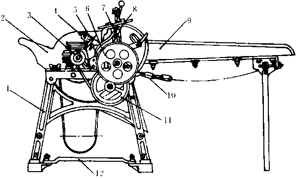
KEY: 1. Frame; 2. Throwing cover; 3. Small single-groove sheave; 4. Blades disk; 5. Movable blade; 6. Changeable gear; 7. Wheel-tension clutch; 8. Suspension bracket; 9. Feeding groove; 10. Chain; 11. Large single-groove sheave; 12. Supporting plate for motor.
Figure 6-12. Chopping action of cylinder-type straw chopper
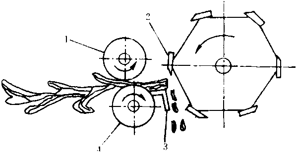
KEY: 1. Upper feed roller; 2. Cylinder blade. 3. Stationary bottom blade; 4. Lower feed roller.
Flywheel choppers
Flywheel chopper operation is illustrated in Figure 6-13, showing a feed chain, upper and lower feed rollers, a stationary lower blade, a cutter and a throwing fan. The straw is fed via the feed chain into the feed rollers, pressed and moved forward by them, then cut into pieces by the combination of upper and lower blades, and it is finally blown by the fan to the storage site or silo.
Figure 6-13. Chopping action of the disk chopper
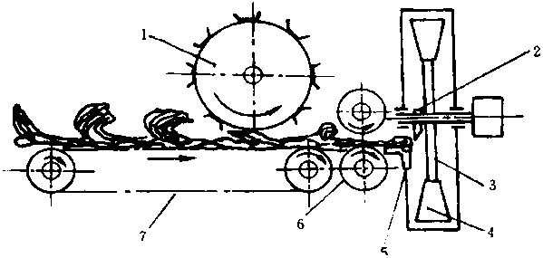
KEY: 1. Feed roller; 2. Blade; 3. Disk; 4. Blower fan; 5. Stationary bottom blade; 6. Feed roller; 7. Feed chain
Figure 6-14 shows the outline of a 93ZP-1000 straw chopper produced by the Liaoning Fengcheng Donsfeng Machinery Factory. Its output is 1 000 kg/hour, the length of chopped pieces are 15 mm or 35 mm and the rotary speed of the main shaft is 8 000 rpm. It has 2 movable blades, a power supply of 3 kW from an integral motor, weighs 110 kg, and its overall dimensions are 95 cm long, 98 cm wide and 140 cm high.
Figure 6-14. Structure of a 93ZP-1000 type chopper
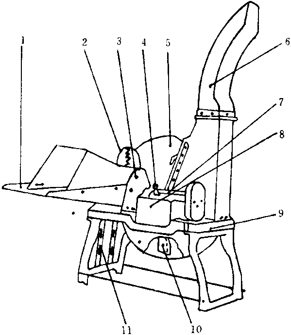
KEY: 1. Feed channel; 2. Bow shape frame; 3. Supporting frame for rollers; 4. Handle for changing position; 5. Cover; 6. Outlet for straw; 7. Connecting shaft; 8. Gearbox; 9. Chassis; 10. Movable blade; 11. Motor frame.
Some types of straw choppers, their technical parameters and their manufacturers in China are shown in Table 6-2.
Grinding methods and grinder types
There are four main grinding methods: impacting, grinding, crushing and sawing (see Figure 6-15). Impacting is suitable for hard and brittle raw materials, such as maize feed; sawing is better for large and fragile feed; and crushing and grinding are used for tough feed.
Table 6-2. Some chopper types, their technical parameters and manufacturers in China
|
Model |
Type & Speed |
Cutting length |
Power (kW) & Capacity |
Weight (kg) & Size (làwàh; cm) |
Price (¥) |
Maker |
|
93ZP-400 Straw |
Flywheel |
|
0.75 |
33 |
|
|
|
|
|
15, 35 |
|
|
730 |
(1) |
|
chopper (Feima) |
900 |
|
400 |
70à55à50 |
|
|
|
93ZP-1000 Straw |
Flywheel |
|
3.0 |
110 |
|
|
|
|
|
15, 35 |
|
|
1 190 |
(1) |
|
chopper (Feima) |
800 |
|
1 000 |
95à98à140 |
|
|
|
93ZP-1600 Straw |
Flywheel |
|
4.0 |
115 |
|
(1) |
|
|
|
15, 35 |
|
|
1 235 |
|
|
chopper (Feima) |
800 |
|
1 600 |
n.a. |
|
|
|
93ZQ-400 Straw |
|
|
|
|
|
(1) |
|
|
Flywheel |
|
0.75 |
35 |
|
|
|
and veg. chopper |
|
5, 7, 15, 35 |
|
|
757 |
|
|
|
900 |
|
400 |
70à55à50 |
|
|
|
(Feima) |
|
|
|
|
|
|
|
9QF-45 Silage |
Flywheel |
|
7.5-11 |
200 |
|
|
|
|
|
16 |
|
|
2 927 |
(1) |
|
chopper (Feima) |
1000 |
|
1 500 |
152à99à80 |
|
|
|
9ZP-4.0 Straw |
Flywheel |
15, 22, 35, 50 |
13.0 |
515 |
|
|
|
|
|
|
|
|
6 300 |
(2) |
|
chopper |
700 |
|
4 000 |
253à248à1773 |
|
|
|
PC C-60 Silage |
Flywheel |
|
10.0 |
1000 |
|
|
|
|
|
6-106 |
|
|
6 300 |
(2) |
|
chopper |
450 |
|
9 000 |
284à177à205 |
|
|
|
9ZP-1.6 Straw |
|
|
3.0 |
|
|
|
|
|
Flywheel |
|
|
n.a. |
|
|
|
and veg. chopper |
|
15, 20, 35 |
Grass 2 000 |
|
|
(3) |
|
|
|
|
|
n.a. |
|
|
|
(Fenglei) |
|
|
Straw 3 000 |
|
|
|
|
|
|
|
4.0 |
|
|
|
|
9DQ-100 Silage |
Flywheel |
|
|
335 |
|
|
|
|
|
9, 20, 28, 60 |
Straw 2 500 |
|
1 680 |
(4) |
|
chopper (Wuye) |
600 |
|
|
150à55à126 |
|
|
|
|
|
|
700-6 500 |
|
|
|
|
93ZT-1000 Straw |
|
|
|
|
|
|
|
|
|
|
3.0 |
190 |
|
|
|
chopper |
|
13, 26 |
|
|
1 188 |
(5) |
|
|
|
|
1 000 |
175à60à110 |
|
|
|
(Xing'anling) |
|
|
|
|
|
|
|
|
|
|
5.5 |
|
|
|
|
9Z-4 Straw |
Cylinder |
|
|
280 |
|
|
|
|
|
15-20 |
Grass 6 000 |
|
4 100 |
(6) |
|
chopper |
1200 |
|
|
n.a. |
|
|
|
|
|
|
Straw 1 500 |
|
|
|
|
|
|
|
n.a. |
|
|
|
|
9Z-8 Straw |
Flywheel |
|
|
|
|
|
|
|
|
15, 14 |
Grass 12 000 |
|
|
(6) |
|
chopper (Ximmu) |
600 |
|
|
|
|
|
|
|
|
|
Straw 3 000 |
|
|
|
|
9ZCA-1.0 Straw |
Cylinder |
|
3.0 |
195 |
|
|
|
|
|
13, 26 |
|
|
800 |
(7) |
|
chopper |
775 |
|
1 000 |
175à60à110 |
|
|
|
9ZC-6 Straw |
Cylinder |
|
10.0 |
1000 |
|
|
|
|
|
6, 13, 25 |
|
|
5 700 |
(8) |
|
chopper |
650 |
|
Silage 6 000 |
250à180à195 |
|
|
|
93ZP-2500 Straw |
Flywheel |
|
7.5 |
320 |
|
|
|
|
|
8-25 |
|
|
|
(9) |
|
chopper (Ximmu) |
850 |
|
2 500 |
238à134à173 |
|
|
NOTE: n.a. = information not supplied.
KEY TO MANUFACTURERS: (1) Liaoning Fengcheng Dongfeng Machinery Plant. (2) Beijing Linhai Agricultural and Livestock Machinery Plant. (3) Beijing Yanjing Livestock Machinery Co. (4) Shijiazhuang Agricultural and Livestock Machinery Plant. (5) Inner Mongolia Wulanhote Livestock Machinery Plant. (6) Shandong Feicheng Chopper Plant. (7) Henan Fugou Scientific Instrument Plant (MOA). (8) Shanxi Xi'an Livestock and Milk Machinery Plant. (9) Xinjiang Livestock Machinery Plant.
Many mills combine different methods. Those commonly found are hammer, fixed head, claw and roller mills. The hammer mill is well suited for straw feed. The roller mill uses a pair of opposed toothed rollers that rotate simultaneously in opposite directions and at different speeds to grind the feed. Roller mills are mainly used for grinding oil cakes. The principles of operation are illustrated in Figure 6-15 (5).
Figure 6-15. Grinding methods for feed
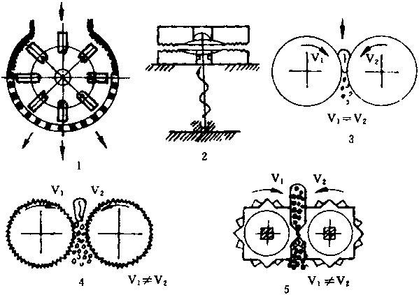
Key: 1. Impacting; 2. Grinding; 3. Pressing; 4, 5. Sawing.
Hammer mills
Hammer mills grind material by the impact of a high-speed rotary hammer. Hammer mills are either tangential-feed or axial-feed types, according to their structure.
Figure 6-16 shows the structure of the 9FQ-50 tangential-feed mill made by the Hongxing Machinery Factory in Jiangxi Province. The mill comprises a feeding part, a grinding chamber and a collector. The feeding part comprises a feed hopper and a feed control flap. The grinding chamber consists of a rotary disk, a hammer, a serrated plate and a screen. The major parts of the collector include a fan, a feed conveying tube and a collection hopper.
Fed from the feed hopper in a tangential direction, the material is impacted and driven to the grinding chamber by the rotating hammers with high speed. The material in the grinding chamber is firstly hit and ground to some extent by hammers, and then thrown at high speed at the serrated plate and the peripheral screen fixed inside the chamber to be further ground through impact with the serrated plate and friction with the screen.
Figure 6-16. Tangential-feed grinder
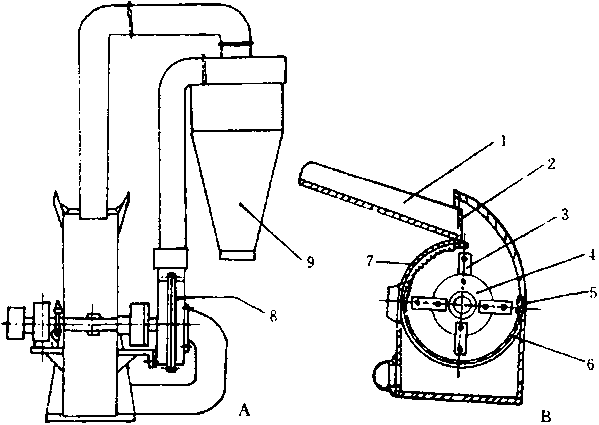
KEY: 1. Feed hopper; 2. Feed control; 3. Swinging hammer; 4. Rotary disk; 5. Small serrated plate; 6. Peripheral screen; 7. Large serrated plate; 8. Fan; 9. Feed gathering (collection) hopper.
The process then repeats until the particles pass through the screen and are discharged from the grinding chamber. The process inside the grinding chamber includes the functions of impacting, shearing and kneading, which improves the efficiency of grinding. The feed product is sucked from the discharging door to the conveying tube by a fan, then enters the collection hopper, and is finally discharged from the collection hopper after the meal settles out from the air stream.
The axial-feed mill (Figure 6-17) differs from the tangential-feed mill in both the direction of feeding and in primary cutting action. Straw fed from the axial-feed hopper is firstly chopped into small pieces by the primary cutting mechanism fixed in front of the grinding chamber, and these pieces then fall into the grinding chamber. Thus the load on the grinding chamber is reduced; and the feeding capability and efficiency of processing improved. The axial-feed mill is especially suited to grinding straw with high moisture content.
The advantages of the hammer mill are high productivity, wide application and fine particle output. It can be used to mill maize, concentrate feed, green grass and various straws with high moisture and fibre content, so it is also called a "grass powder miller." However, energy consumption is high.
The fixed-head mill differs from the hammer mill in that its blade is fixed to the rotary disk rather than connected to it by a pin, so it has much higher grinding capacity.
Figure 6-17. Axial feed mill. A. Outline; B. Operation
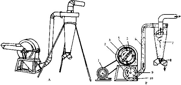
KEY: 1. Motor; 2. Housing; 3. Ring screen; 4. Hammer; 5. Primary cutter; 6. Conveying tube; 7. Feed collection (gathering) hopper; 8. Discharging door and tube; 9. Fan; 10. Frame.
Claw mills
Claw mills hit and grind material with claws fixed in a rotating disc, and are suitable for concentrate grinding because of compact structure, small volume and light weight.
Figure 6-18 illustrates the structure of a claw mill with its feeding, grinding and discharging parts. The feeding includes a feed hopper, a feed control door and a feed tube. The grinding part consists of a rotary serrated disk, a stationary serrated disk and a ring screen. Claws are fixed on the rotary and the stationary disks alternatively. The discharging part is a tube situated in the bottom of the machine.
After flowing into the grinding chamber from the feed hopper via the feeding door, the material is impacted, sheared, kneaded and gradually rubbed by claws into powder. At the same time, the airflow formed by high-speed rotation of the rotary serrated disk blows the powder out through the ring screen.
Figure 6-18. Claw mill
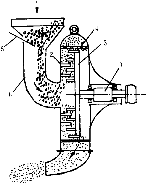
KEY: 1. Main shaft; 2. Stationary serrated disk; 3. Rotary serrated disk; 4. Ring screen; 5. Door to control material input rate; 6. Feed tube.
Factors influencing the effects of grinding
(i) Type of material to be ground. The grinding output with the same energy consumption differs according to raw material. Output with cereal feed is higher than with roughage. With a screen hole diameter of 1.2 mm and a moisture content below 15 percent, the output in kg/kW is 45-60 for maize and sorghum; 17-22 for chaff; 12-16 for sweet potato vines; 8-12 for maize stover; 7-12 for sorghum stover; 6-10 for legume straw; and 3-4 for maize cobs (2 mm screen hole diameter).
(ii) Moisture content. The higher the moisture content, the lower the output and the poorer the energy efficiency. Generally, moisture content should not be higher than 15 percent.
(iii) Rotary speed of main shaft. Each type of mill has a range of rotary speeds for the main shaft to obtain high output and low energy consumption for each feed. If the rotary speed is too low, the grinding capacity is decreased and feed discharge is hampered, so productivity is also reduced. In contrast, if the rotary speed is too high, idle energy consumption is increased, as well as wear, tear and vibration, and the total energy consumed is higher. The line speed for hammer mills made in China in recent years is about 70 -90 m/sec.
(iv) Feed rate. If the feed rate is too high, ground feed can not be discharged from the grinding chamber at the same rate, which results in clogging, which affects capacity. In contrast, if the feeding rate is too low, the milling capacity is not fully used and efficiency decreases.
The main mill types made in China are listed in Table 6-3.
The kneading machine is a new kind of straw processing technique developed in China, combining chopping with grinding. The machine processes residues, especially maize stover, into thin thread segments of 8-19 cm, completely destroying its node structure. Palatability is greatly improved, and the intake of the entire crop is also increased to 95 percent from the original 50 percent. The structure of the kneading machine is shown in Figure 6-19. In operation, the rotor, diameter 40 cm, rotates at a high-speed (2 856 rpm) driving 16 hammers arranged in 4 groups, which impact the straw fed continually. A tilted serrated plate, whose teeth are arranged helically and with changeable height, and 6 stationary blades are fixed to the concave plate of the machine, in order to keep the impacted straw moving in axially with the help of a fan. Taking the 9RC-40 kneading machine, made by the Beijing Linhai Agricultural and Livestock Machinery Plant, as an example: the power supply is 7.5 -13 kW (the machine can also be driven by 8.82 -11.0 kW from a four-wheel drive tractor) and the output of model I is up to 1 000 kg/hour, with 2 000 kg/hour from model II.
The kneading machine can increase straw utilization considerably simply by physical processing and it is well suited for maize stover, which already has high nutrient value. Energy consumption is high, 1 to 2 times that of a normal chopping machine of the same output, because the final particles are finer. Because straw can also be softened during ensilage or ammoniation, this chopper can meet animals' requirements when they do not directly eat straw.
The main types and technical parameters of the kneading machines made in China are shown in Table 6-4.
Table 6-3. Characteristics of some grinders produced in China
|
Model and Type* |
Speed |
Output |
Capacity |
Power |
Weight (kg) |
Price |
Maker |
|
9FQ-40B Feed |
3800 rpm |
95 |
800 |
7.5 |
150 |
790 |
(1) |
|
mill (Fenglei) [H] |
400; - |
22 |
160 |
|
83à79à90 |
|
|
|
9QF-50B Feed |
3250 rpm |
95 |
1300 |
13.0 |
240 |
1 600 |
(1) |
|
mill (Fenglei) [H] |
500; - |
20 |
260 |
|
107à106à99 |
|
|
|
6FC-308A Feed |
3800 rpm |
n.a. |
600 |
5.5 |
120 |
760 |
(2) |
|
mill [Fixed head] |
308; - |
|
- |
|
75à56à120 |
|
|
|
9FQ40 -20 Feed |
n.a. |
n.a. |
1000 |
7.5-11 |
170 |
850 |
(2) |
|
mill [H] |
|
|
- |
|
90à89à81 |
|
|
|
9F-45A High efficiency feed |
3600 rpm |
90 |
900 |
|
130 |
|
|
|
|
|
|
|
10.0 |
|
865 |
(3) |
|
mill (Fengshou) |
450; 1.2 |
30 |
300 |
|
88à87à105 |
|
|
|
[H] |
|
|
|
|
|
|
|
|
9F-36 Feed mill |
4 500 rpm |
|
1000 |
|
85 |
|
|
|
|
|
n.a. |
|
7.5 |
|
780 |
(3) |
|
(Fengshou) |
360; 2 |
|
280 |
|
75à99à114 |
|
|
|
9FQ40-20 Straw |
|
|
|
|
|
|
|
|
|
3 770 rpm |
|
1100 |
|
170 |
|
|
|
Mill (Fengshou) |
|
n.a. |
|
7.5-11 |
|
850 |
(3) |
|
|
n.a. |
|
Ð |
|
99à89à81 |
|
|
|
[H] |
|
|
|
|
|
|
|
|
9FQ-40 Feed |
- |
95 |
900 |
7.5-11 |
200 |
1 297 |
(4) |
|
mill [H] |
400; 2.0 |
25 |
200 |
|
90à57à81 |
|
|
|
9F-45A Feed |
3 600 rpm |
|
1090 |
|
|
|
|
|
|
|
n.a. |
|
11 |
n.a. |
n.a. |
(5) |
|
mill [H] |
-; 2 |
|
Ð |
|
|
|
|
|
9FS-45A Feed |
3200 rpm |
|
780 |
|
|
|
|
|
|
|
n.a. |
|
11 |
n.a. |
n.a. |
(5) |
|
mill [C] |
-; 2 |
|
Ð |
|
|
|
|
|
93FC-50 Straw |
|
|
|
|
|
|
|
|
|
3437 rpm |
134 |
1519 |
|
|
|
|
|
Mill (Hongxing) |
|
|
|
15 |
|
8 000 |
(6) |
|
|
500; 3 |
78 |
706 |
|
184à105à95 |
|
|
|
[H] |
|
|
|
|
|
|
|
|
9FQ40-20 Feed |
|
|
|
|
|
|
|
|
|
3730 rpm |
130 |
1000 |
|
180 |
|
|
|
mill (Hongxing) |
|
|
|
7.6 |
|
1 200 |
(6) |
|
|
400; 2 |
22 |
165 |
|
n.a. |
|
|
|
[H] |
|
|
|
|
|
|
|
|
9FQ-50 Feed |
|
|
|
|
|
|
|
|
|
3440 rpm |
69 |
884 |
|
488 |
|
|
|
mill (Hongxing) |
|
|
|
13 |
|
1 800 |
(6) |
|
|
500; 1.2 |
13.7 |
175 |
|
156à61à210 |
|
|
|
[H] |
|
|
|
|
|
|
|
|
9F-37-1 Feed |
|
|
|
|
|
|
|
|
|
4000 rpm |
|
250 |
|
125 |
|
|
|
mill (Lingfeng) |
|
n.a. |
|
7.5 |
|
700 |
(7) |
|
|
370; 1 |
|
50 |
|
69à70à68 |
|
|
|
[H] |
|
|
|
|
|
|
|
|
9F-500 Feed |
|
|
|
|
|
|
|
|
|
3250 rpm |
> 125 |
850 |
|
200 |
|
|
|
mill (Dongyue) |
|
|
|
11 |
|
1 320 |
(8) |
|
|
500; 3.5 |
> 20 |
400 |
|
154à97à154 |
|
|
|
[H] |
|
|
|
|
|
|
|
|
9F-400 Feed |
|
|
|
|
|
|
|
|
|
3000 rpm |
> 142 |
600 |
|
150 |
|
|
|
mill (Dongyue) |
|
|
|
7.5 |
|
1 100 |
(8) |
|
|
400; 3.5 |
> 25 |
250 |
|
149à99à146 |
|
|
|
[H] |
|
|
|
|
|
|
|
|
93Fc-650 Straw |
2500 rpm |
107 |
800 |
|
n.a. |
|
|
|
|
|
|
|
11 |
|
|
(9) |
|
Mill (Xinmu) [H] |
650; 4 |
46.8 |
560 |
|
2157à1274à1505 |
3 200 |
|
NOTES: *Types are [H] = hammer; [C] = claw. n.a. = information not provided.
KEY TO MAN UFACTUR ER S: (1) Beijing tonnexian Grinder Plant. (2) Shanxi Huguan Farm Machinery Plant. (3) Inner Mongolia Ningchen General Machinery Plant. (4) Liaoning Fengchen Machinery Plant. (5) Helongjiang Anqing Farm and Livestock Plant. (6) Jiangxi State Running Hongxing Machinery Plant. (7) Gangxi Hoxian Agricultural Machinery Plant. (8) Shandong Taishan Farm and Livestock Machinery Plant. (9) Xinjiang Livestock Machinery Plant
Figure 6-19. Illustration of kneading machine structure
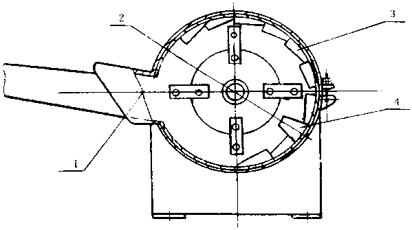
KEY: 1. Smooth plate; 2. Hammer rotor; 3. Unequal height teeth; 4. Stationary blade.
Table 6-4. Characteristics of some kneading machines in China
|
Model and type* |
Rotor Æ |
Power (kW) |
kg/kWh |
Weight (kg) |
Price (.) |
Maker |
|
93RC-40 Straw Kneading |
400 |
7.5-10 |
|
120 |
|
|
|
|
|
|
100 |
|
1 640 |
(1) |
|
Machine [H] |
2500 |
1000 |
|
13712669 |
|
|
|
93RC-40 Straw Kneading |
400 |
7.5-13 |
|
130 |
|
|
|
|
|
|
n.a. |
|
2 500 |
(2) |
|
Machine [H] |
2610 |
2000 |
|
15366127 |
|
|
|
K-67-50 Straw Kneading |
500 |
|
|
n.a. |
|
|
|
|
|
n.a. |
n.a. |
|
2 000 |
(3) |
|
Machine [H&B] |
n.a. |
|
|
n.a. |
|
|
|
9RS -1.5 Straw Kneading |
n.a. |
17-22 |
|
n.a. |
|
|
|
|
|
|
n.a. |
|
2 800 |
(4) |
|
Machine [H&B] |
1400 |
1500 |
|
16050122 |
|
|
|
9RS -0.7 Straw Kneading |
n.a. |
5.5-10 |
|
n.a. |
|
|
|
|
|
|
n.a. |
|
1 800 |
(4) |
|
Machine [H&B] |
2000 |
700 |
|
1323783 |
|
|
|
|
Chopping 900 |
|
|
|
|
|
|
9RSL -50 Multi-function feed |
|
7.5 |
|
195 |
|
|
|
|
Tearing 2000 |
|
n.a. |
|
1 500 |
(5) |
|
Kneading Machine [H&B] |
|
5000 |
|
21554150 |
|
|
|
|
n.a. |
|
|
|
|
|
|
9RC-40 Straw Kneading |
|
7.5 |
|
160 |
|
|
|
|
n.a. |
|
n.a. |
|
n.a. |
(6) |
|
Machine [H] |
|
1000 |
|
n.a. |
|
|
|
9FRQ-40B Straw Kneading |
|
|
|
n.a. |
|
|
|
|
n.a. |
n.a. |
n.a. |
|
750 |
(7) |
|
Machine [D] |
|
|
|
n.a. |
|
|
|
93F-45 Straw Kneading |
450 |
4 |
|
600 |
|
|
|
|
|
|
50 |
|
3 200 |
(8) |
|
Machine [H] |
2500 |
200 |
|
18080105 |
|
|
NOTES: * machine types are [D] = disc; [H] = hammer; [H&B] = hammer and blade.
n.a. = information not supplied
KEY TO MANUFACTURERS: (1) Liaoning Fengchen Machinery Plant. (2)Beijing Linhai Farm and Livestock Machinery Plant. (3) Helongjiang Achen Huajianuy Metal Structure Plant. (4) Inner Mongolia Chifeng General Livestock Plant. (5) Helongjiang Anda Livestock Machinery Plant. (6) Helongjiang Achen and Mechanical Electrical Equipment Plant. (7) Jilin Jutai Farm Tool Plant (8) Shanxi Xi an Livestock and Milk Equipment Plant.
Kneading and cutting machine models 9LRZ-80 (Figure 6-20) and 9RZ-60 (Figure 6-21) were designed by the Non-conventional Feed Institute, China Agricultural University. They passed appraisal by MOA in 1998. The appraisal said that the machines were an innovation in China, with world-leading performance.
Figure 6-20. Type 9LRZ-80 kneading machine
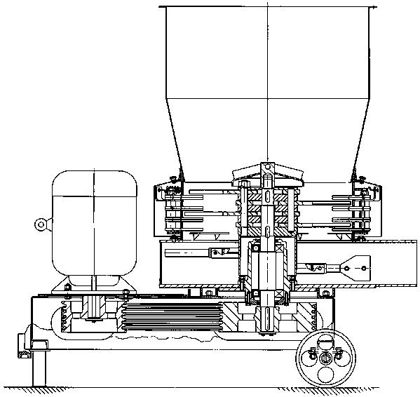
Kneading and cutting machines combine cutting, kneading and mixing in one operation. Maize stover, wheat and rice straw, bean vine and tuber vine can be processed to thread-like soft material.
The future developments of the series include the replacement of the cutting blades in the chopper by running blades; and the incorporation of a hammer in the kneading machine and of a mixing rotor in the mixer. There are now 16 running blades and 6 sets of fixed blades. Changing the number of running blades and fixed blades will alter the cutting length and softness. The material will be thrown to the inner region of the cylinder, and will be chopped, cut and kneaded to thread-like form. When tubers and concentrate are fed into the machine together, material will be cut and mixed.
Figure 6-21. Type 9RZ-60 kneading machine
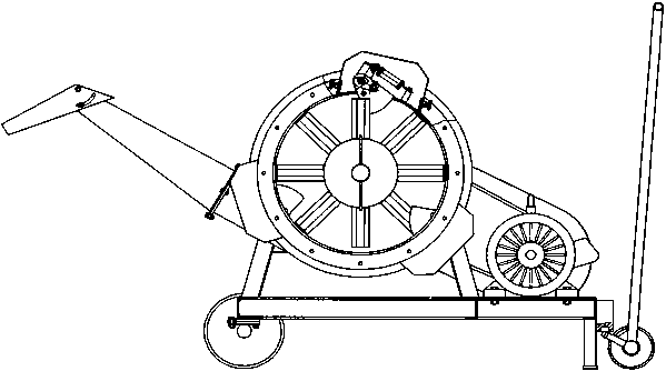
The new series has the following advantages:
The new axle structure increases the feeding capacity.
In the working cylinder, the running and the fixed blades will cut and knead at same time, so that energy can obviously be reduced.
By simply changing blade numbers, different lengths and softness can be obtained. It is suitable for green and dry materials, and especially for wet and tough material (such as palm nut shell, reeds, and chaste tree twigs).
It is suitable for maize stover silage. The processed material can be compacted easily. Without nodes remaining, the whole stalk can be eaten by the animal.
The 9LRZ-80 is appropriate for large farms. It requires a power source of 22-30 kW, and has a capacity of 6-8 t/hour, and an output of 0.39 tonne/kWh. Its node breaking efficiency is 99 percent.
The 9RZ-60 kneading and cutting machine can be equipped with a 15 kW electrical motor. The 9RZC-60 has an 18 hp diesel engine. Both have an output of 3-4 t/hour, and are suitable for medium-sized farms.
Table 6-5. Specifications of kneading and cutting machines
| |
9LRZ-80 |
|
9RZ-60 |
|
|
Power (kW) |
22 |
|
11-15 |
|
|
Productivity (t/hour) |
|
|
|
|
| |
With 14-40% moisture |
3-5 |
|
2-3 |
|
With 40-70% moisture |
6-8 |
|
3-4 |
|
|
Grade of processed material |
|
|
|
|
| |
< 50 mm |
|
ca 78% |
|
|
50 - 100 mm |
|
ca 20% |
|
|
|
> 100 mm |
|
ca 2 % |
|
|
|
Node breaking efficiency |
|
> 99 % |
|
|
Compared to a chopper, the 9LRZ-80 can save 2 160 kWh and 1 080 work-days for processing 6 000 tonne of green stalks. Total savings are about ¥ 3 000.
After being ground into meal, having had concentrates and other nutrient elements added, straw makes a complete feed, and can be pressed by a pelleting machine. The pelleted feed, containing all nutrients, increases palatability and intake, and at the same time decreases feed waste and reduces feeding time. However, the cost of equipment for pellet processing is high. The machine consists of a pelleting device, a steam generator, an oil and molasses doser, a cooling device, a separator and a sieve.
There are two types of pelleters: disk die and ring die pelleters.
Disk die pelleter
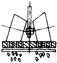
Several disk die pelleters have been made in China. Figure 6-22 shows a disk die pelleter, comprising a screw conveyor, a gear-box, a stirrer and a pelleting device. The screw conveyor, whose rotary speed is adjustable, is mainly used to control the charging rate. The stirrer situated under the conveyor stirs the material, admitting steam through a side hole to heat and cook the material while it is transferred to the pelleting device. Inside the die there are 2 to 4 press rollers and a disk with many holes (shown in Figure 6-23). In operation, the disk rotates at a speed of 210 rpm. After falling onto the disk die, the cooked meal is distributed evenly by a spade and forced through the round holes of the die by the press. The cylindrical pellets from the die are then cut into pieces 10-20 mm long by a blade under the disk. Disk presses can be classified into three types: movable die, movable roller and movable die and roller types. Hole diameter in the die can be 4, 6 or 8 mm. The diameter of the roller ranges from 160 to 180 mm.
Figure 6-22. Pelleter with disk die
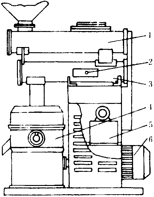
KEY: 1. Screw conveyor; 2. Steam inlet; 3. Stirrer; 4. Press; 5. Wormwheel box; 6. Motor.
Figure 6-23. Operation of the disk die
Ring die pelleter
The ring die press has been widely used in engineering. Figure 6-24 is an illustration of its operation. The main parts are a screw conveyor, a stirrer, a pelleting device and a drive mechanism. The screw conveyor, whose rotary speed can normally be changed gradually in the range of 0-150 rpm, is used to control the loading rate. A side opening to the stirring chamber allows steam to be injected. In the stirring compartment, the meal is mixed with over-saturated high-pressure steam. Sometimes oil, molasses and other additives are added during mixing. When ideal conditions can not be met, water can be used instead of steam, but in this case mixing is poor, output is decreased, and energy consumption and friction are increased.
The mixed meal goes into the pelleting device, which consists of a ring die and pressing rollers. In operation, the ring die rotates, making the rollers turn and press the material through the cylindrical holes of the ring die. The cylindrical pellets rotate with the ring die, and are cut by a blade. The larger the hole diameter, the higher the output of the machine and the lower the energy consumption. Hole diameter is determined by animal requirements.
Figure 6-24. Operation of a pelleter with ring die
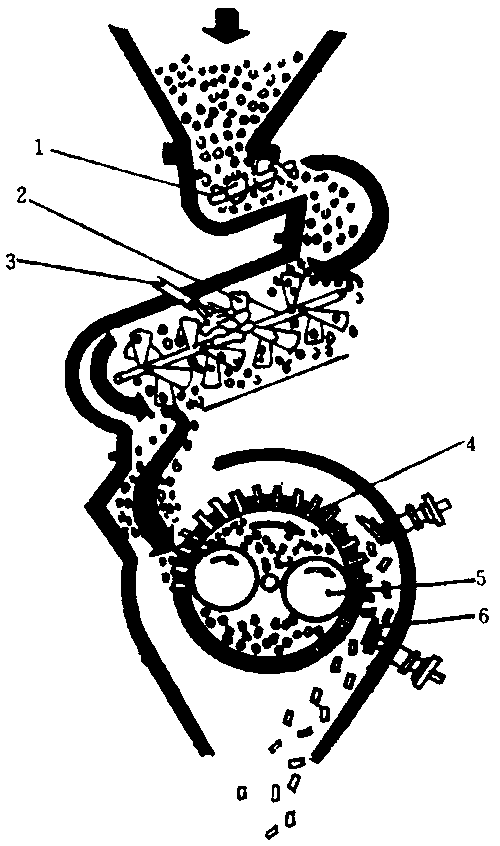
KEY: 1. Srew conveyor; 2. Stirrer; 3. Steam or air inlet; 4. Ring die; 5. Rollers; 6. Cutter.
Wafers are about ten times the size of pellets. The wafering machine made by the Guangdong Huada Machinery Factory can make rectangular wafers 25 ¥ 25 mm or 30 ¥ 30 mm, and also cylindrical wafers of 8-30 mm in diameter. The density varies from 0.6 to 1.0 g/cm3, and the bulk weight from 0.4 to 0.6 tonne/m3. The output is 600-1 000 kg/hour. Five operators are needed.
The 93KWH-40 waferer and the 93KWH complete wafering set have been developed by the Jiangxi Hongxing Machinery Plant. The rotary speed of the main press shaft is 167 rpm, the output is 300-600 kg/h, and the power needed 37 kW. The whole system's energy needs are 62.5 kW.
After milling and addition of concentrates, chemical additives and other minerals, the straw is wafered to increase nutrient value, intake and digestibility. The wafered feed is not only easy to transport, to store and to feed, but also very convenient for marketing due to its high density.
The wafering process is shown in a flow chart (Figure 6-25). After size reduction (chopping, grinding) to a specified size, controlled by the screen holes, roughage such as rice straw, wheat straw, maize stover, bulrush and sunflower stem is transported by forced air to the cyclone (2) and then to the buffering bin (3). The material from the bin (3) is conveyed via a double-screw conveyor (4) and a rationing conveyor (5) to the mixer (8), where chemical additives and concentrates are added separately at prescribed rates from hoppers (6 and 7). At the same time, water and steam are also added to the mixer. The uniformly mixed material falls to the wafering machine (11) to be made into cubes. The cubes are transferred to a horizontal cooler (13), and then drop to the packing machine.