![]()
![]()
![]()
6.1 Roads
6.2 Watercourse Crossings
6.3 Log Pond and Wharf
6.4 Quarries
|
OBJECTIVES To plan extraction systems that are safe and economical. To minimise the loss of productive forest area. To minimise sedimentation of watercourses. To minimise disturbance to excluded areas. To provide and maintain good surface and side drainage during
and after construction of roads and other infrastructure. |
6.1.1 Road Classification
Major roads
Major roads are those that can carry trucks with large log volumes (e.g., 2,500 m3 or more per week averaged over the logging operation).
Minor roads
Minor roads are those that can carry trucks with moderate log volumes (e.g., between 1,000 and 2,500 m3 per week averaged over the time that they are in operation).
Haul tracks
Haul tracks are those that can carry trucks with small log volumes (e.g., less than 1,000 m3 per week averaged over the time that they are in operation).
6.1.2 Road Design
Location
Roads should be designed in locations according to the following:
Areas to avoidForest Authority should be responsible for the co-ordinated development of infrastructure including location of roads;
Areas where roading should be avoided are:
Suggested maximum side slopes
- gullies,
- swamps and mangroves,
- wetlands/watercourses,
- conservation/reserve areas.
50%.[2]
Suggested maximum batter slopes
100%.
(This will be on moderately stable soils.)
Road grade specification
|
Road class |
Preferred maximum allowable grade (%) |
Preferred maximum adverse grade (%) |
Preferred maximum length at maximum grade |
|
Major road |
10 |
8 |
1000 m |
|
Minor road |
15 |
10 |
750 m |
|
Haul tracks |
18 |
12 |
600 m |
Steeper grades (up
to 20%) for short sections (maximum 500 m) would be acceptable if this reduces
the disturbance from road construction. Any two sections of
road at absolute maximum gradient should be separated by 100 m of level or lower
gradient.
Roading width should
be kept to a minimum but will depend on the truck width and travel
speed.
Road widths
Suggested maximum road widths are:
|
|
Gravel Surface |
Compacted Clay Surface |
|
Major road (2-way) |
10.0 m |
15.0 m |
|
Major road (1-way) |
6.3 m |
11.0 m |
|
Minor road |
6.0 m |
7.3 m |
|
Haul track |
5.0 m |
6.0 m |
Curve widening will be required on corners to allow for off-tracking of trailers. Recommended road curves and widening of corners to allow for off-tracking on all road classes are:
Off-tracking on curves (metres vs radius of curvature) based on a vehicle with overall length of 14 m
|
Radius (m) |
25 |
30 |
40 |
50 |
60 |
75 |
100 |
150 |
200 |
|
Off-tracking |
1.65 |
1.20 |
0.95 |
0.80 |
0.70 |
0.55 |
0.40 |
0.35 |
0.20 |
NOTES: Additional width is required in each lane, ie a two-lane road requires a total widening to the roadway width of twice the tabulated value.CURVES
Fit curves to the
topography. The minimum radius of the curve is related to visibility and the
speed of vehicles will be travelling on the road. These are shown in the table
below.
|
Design speed |
30 kph |
50 kph |
80 kph |
|
Minimum radius (use may require signs) |
25 m |
30 m |
55 m |
|
Desirable minimum radius |
35-75 m |
75-120 m |
140-300 m |
|
Minimum sight distance required |
30 m |
64 m |
120 m |
|
Meeting sight distance |
50 m |
100 m |
220 m |
6.1.3 Road and Haul Track Construction
Timing of constructions
Preliminary roadline
clearing should be undertaken well ahead of final construction in any one site
to reduce sedimentation from undrained sections.
Major and minor
roads are to be completed well before logging.
Construction is not
to commence more than 12 months before harvesting.
Survey requirements
Survey and mark the
centreline of roads and haul tracks on the ground using the defined
specifications.
Locate obligatory
control points.
Locate log
landings.
Roadline development
All merchantable
stems are to be felled and extracted along the road alignment.
All clearing debris
is to be heaped and burnt within the area of roadline (or roadside log landing
if this is included in the harvesting plan).
Organic debris
should not be used as fill.
Soil heaps, berms
and debris stockpiling along roadside is prohibited.
TEMPORARY TRACKS
These are tracks
constructed to allow machinery to gain access to an area ahead of the main
construction activity.
They are not generally permitted. Their location and justification should be discussed in the harvesting plan. A field inspection by the Forest Authority Officer is suggested before approval is considered.
Where a temporary
track is approved, it should be:
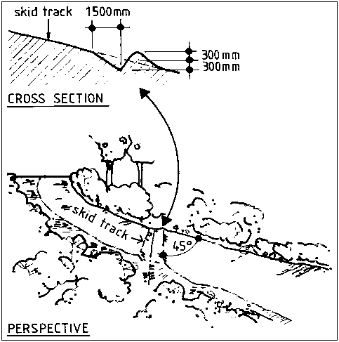
- sited so as to avoid felling trees greater than 30 cm dbh;Road and haul track drainage
- less than 4 metres wide;
- stabilised, with cross drains constructed immediately after use has been completed.
SPACING
Drain all roads to
minimise sediment production. Road drains should be constructed as
follows:
- at changes of slope;
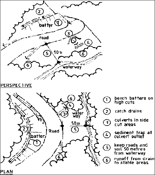
- within 50 metres of watercourse crossings;
- additional drains as needed to stay within the maximum spacing requirements.
Side drains that are
adjacent to roads that have been box-cut should have rock bars at half the
maximum drain spacing.Indicative drain spacings used in Asia and the Pacific are as follows:
|
Centreline gradient (%) |
Maximum drain spacing (metres) |
|
|
Unstable Soil |
Stable Soil |
|
|
0-15% |
40 |
60 |
|
15-20% |
20 |
40 |
|
20-25% |
10 |
20 |
|
25%+ |
- |
15 |
DRAINAGE
The following suggestions are made to promote suitably drained roads and haul tracks:
DRAIN OUT-FLOW
Drains are not to
directly enter watercourses but should be diverted into surrounding vegetation
at least 50 m before a watercourse.
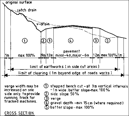
Figure 6-2: Road and Haul Track Drainage Construction
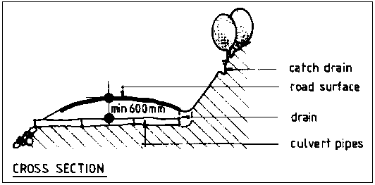
Figure 6-3: Silt Traps on Drains
Major and minor roads
Roads are to be
located on elevated areas wherever possible to minimise side cutting, width of
clearing and drainage problems.
Where side cutting
is necessary, cuts are to be formed as shown in Figure 6-4.
Where side cutting
is not necessary, earthworks should limited to the width allowed for the
pavement plus verge and table drains on either side. An additional width to
allow for travel by track machines may be approved following inspection by the
Forest Authority Officer. Approval must be received before felling and clearing
commences.
Surfacing material
can be coral, crushed rock, compacted clay or gravel.
Figure 6-4: Major and Minor Road Construction
Haul Tracks
Haul tracks are to
be located on spur lines (ridges) wherever possible to minimise side-cutting and
drainage problems.
Side-cutting should
be formed as shown in Figure 6-4.
Where side-cutting
is not necessary, the width should not exceed that specified for the travel
surface.
Revegetating cut and fill areas
Revegetation should be undertaken and can be carried out using a range of measures such as cereal cover crop (e.g., rice, millet), grass or seed of fast-growing shrubs or trees immediately after construction.
Limits to road construction
Wet weather
restrictions apply.
Road construction
should not occur during the wet season.
Road maintenance
All drains, pipes,
culverts and bridges are to be kept open at all times. They are to be inspected
thoroughly and repaired before the onset of the wet season/monsoon and during
periods of heavy rainfall.
Removal of soil from
the surface of roads, except during initial construction, is not
permitted.
Road surface
maintenance should be performed as needed. Crossfall and road shape should be
maintained to allow effective drainage.
Good surfacing
gravel should not pushed to the road edge or into drains.
Road closure and rehabilitation
Consultation with
local stakeholders should be conducted prior to deciding on road closure. All
feeder roads approved for closure should be decommissioned and
rehabilitated.
Remove log culverts
and temporary bridges to allow unobstructed waterflow (Figure 6-5).
The road surface
should be maintained intact so the road can be reopened when required.
Cross-drains (Figure
6-6) should be installed at the following density.
|
Road gradient |
Space between drains |
|
0-3% |
Nil required |
|
4-14% |
120 m |
|
15-20% |
80 m |
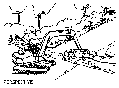
Figure 6-6: Cross-Drain System
|
OBJECTIVES To provide permanent bridges or culvert crossings (to be retained after harvesting) over all watercourses crossed by roads, constructed with durable materials. To provide temporary bridges or crossings in areas where roads will be decommissioned after harvesting. To restrict disturbance to watercourses and surrounding buffer areas to that necessary for crossings. To minimise sedimentation of watercourses. |
Bridges
Bridges should be used for road crossing of all Class 1, 2 and 3 streams (except where fords are acceptable). They may also be used to cross other watercourses.
Culverts or pipes
Culverts or pipes should be used for crossing gullies and waterways (if bridges are not used). FAO Watershed Management Field Manual Guide 13/5 provides details for culvert sizes.
Fords/low-level crossings
Fords are acceptable when:
Temporary bridges
Temporary bridges may be used for roads after harvesting.
Log clusters with earth fill
Log clusters with earth fill should NOT be permitted for any watercourse in any situation.
6.2.2 Construction of Watercourse Crossings
Location
The location of all watercourse crossings is to be inspected and approved by the Forest Authority Officer prior to construction. The chosen location of the watercourse crossing should:
Temporary crossings
- are immediately downstream of straight and stable watercourse sections;
- have easy high bank access;
- do not require deep box cuts;
- require minimum alteration or disturbance to the high bank;
- have stable beds.
Temporary crossings are permitted to allow equipment involved with the construction of the watercourse crossing to be moved to the other side. They should be constructed as follows:
Permanent crossings
Permanent crossings
must be of a size to allow wet season flood flows to pass without damage to the
crossing or its foundations. (Government authorities may be able to provide
information on flood levels, as will local inhabitants.)
The height from the
stream bed to the bottom of the bridge deck must be at least equal to the height
of the high bank.
The width of the
crossing must be at least equal to 80% of the width of the watercourse measured
from high bank to high bank.
All water crossings
must be single lane.
Earthworks
Excavators should be
used where possible for the construction of all watercourse crossings. Manual
labour should also be considered as appropriate in specified
circumstances.
All earthworks
should be carried out so as to prevent soil entering the watercourse. No soil is
to be used or placed past the high bank without first having erected and secured
a suitable barrier.
Road construction
within the buffer area should be by end-haul.
All spoil should be
removed to outside the buffer areas or placed in road fills where
possible.
Watercourse buffer
vegetation should be retained to the edge of the crossing.
Foundations
Bridge and culvert
foundations are to be located on stable materials.
The foundations are
to be excavated to a solid base and not formed by pushed material.
Construction
No machinery will operate in the watercourse during construction.
Bridges
Approaches must have
a straight and level alignment for a minimum of 10 metres on either
side.
Decks can be
constructed of durable sawn timber, or other non-erosive material (e.g., clean
rock fill). Soil fill or soil covering is not permitted unless the timber deck
is completely covered with material such as geotextile and has protection beams
on both sides.
All parts of the
bridge must be well anchored to prevent their washing away.
The stream banks
adjacent to the bridge, on both the top and bottom sides, must be stabilised
using wings of durable logs, stone pitch or other equivalent construction
(Figure 6-8 and Figure 6-9).
Figure 6-7: Temporary Bridge
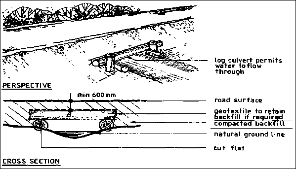
Figure 6-8: Timber Bridge
Figure 6-9: Soil Covered Timber Bridge
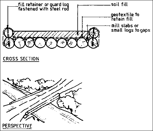
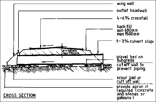
Culverts and pipes
May have earth fill,
but must have stable abutments constructed to the level of the running surface
to prevent spoil entering watercourse.
Scour pads
(structure to minimise erosion) should be provided at culvert exits. They should
be used if higher energy water flow is likely (Figure 6-10).
All culverts should
have a cut-off wall to prevent erosion under the pipe.
The head and outlet
walls should be stabilised with log or stone pitched walls.
Culvert gradients
should be 1-3%.
Use of log culverts
is discouraged and should only be used for culverts on temporary
roads.
If log culverts are
used, geotextile or another retaining mechanism should be used to retain
backfill.
Figure 6-10: Culvert Construction
Fords/low-level crossings
Low level crossings should:
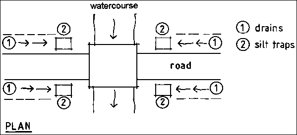
Silt traps
Silt traps are to be
provided at the four corners of bridges and culverts.
Silt traps should be
cleaned regularly.
|
OBJECTIVES To minimise the area used for processing and shipping of logs. To avoid adverse impacts on the marine environment. To store logs in a manner that minimises damage and loss. To prevent log off-casts from entering watercourses or the
sea. |
A log pond and wharf
loading ramp plan, showing the location and construction specifications should
be submitted to the relevant authority prior to construction.
Gently sloping areas
(up to 6%) are preferred to promote drainage.
Constructing log
ponds by filling reclamation areas below low-water mark will only be considered
where:
- there is no alternative;
- construction and operation will not damage the adjacent marine environment;
- and drainage water is directed away from the sea.
Locate to provide
the best and most direct access for log ship barges. Deep-water ports are
preferred to reduce the cost and disturbance associated with barging
operations. Retain a 50-metre
buffer area between the log pond and the shoreline (or mangrove vegetation) or a
watercourse.
Clearing of
shoreline or river frontage vegetation (including mangroves) should be limited
to that necessary to construct the wharf and associated log storage area. A
maximum frontage of 100 metres is desirable.
Timing of construction
Construct the log
pond and wharf in dry weather.
Excavators should be
used where possible for construction to minimise disturbance to surrounding
environment.
Design
LOG POND
Log pond areas
should be well drained. Spoon drains (3-4 metres wide and 30 cm deep),
constructed at a maximum interval of 40 metres will channel runoff to vegetated
outlets. The maximum slope of spoon drains should be 1-3%.
The major crossing
points of drains should be gravelled to a depth of 30 cm. The gravel should not
restrict the flow of water along drains. Where gravel is not available, crossing
points should be corded so that the top of the cording is level with the base of
the drain.
Drains should not
directly enter water bodies. Water must be filtered by a designated filter
strip.
Log and waste
storage areas between the drains should be elevated with a crossfall of 4-6% and
should be at least 1 m above high tide level.
Fuel storage areas
should be bunded and located at least 50 m from the high tide mark.
WHARF
Construct using
clean gravel fill only. Soil material should not be used.
The loading face of
the wharf should be a wall-type construction with a top log. Walls may be
constructed of round timbers, rock or other material able to prevent slumping of
wharf fill into the sea. All timbers should be secured to prevent their falling
into the sea. Only durable timber species should be used.
Maintenance
Drains should be
kept open at all times.
Silt traps should be
cleaned regularly.
Log storage areas
and the surface of the wharf should be kept elevated by applying gravel or coral
as required.
Existing log ponds and wharves
Earthworks and other
rehabilitation are required to bring existing facilities to these
standards.
Decommissioning of log ponds and wharves
The drainage system
should prevent stormwater runoff from the site entering watercourses or the
ocean without first passing through a filter strip. Water bars may be
required.
All stream beds
should be restored to allow unimpeded flow of water.
All waste, waste oil
and fuel must be removed from the site.
6.3.1 Barging/Beach Loading
Location
An area should be selected that will:
minimise damage to
the shoreline;
minimise the
requirement for machinery to enter the water (machinery should only enter the
water with the approval of the Forest Authority Officer).
Design
Adequate drainage
(as detailed for log ponds) must be installed.
If damage from
vehicles might occur on the waterline strip, cording should be installed as a
protective measure.
Decommissioning/Rehabilitation
The drainage system
should prevent stormwater runoff from the site entering watercourses or the
ocean without first passing through a filter strip. Water bars may be
required.
All stream beds
should be restored to allow unimpeded flow of water.
All refuse, waste
oil and fuel must be removed from the site.
Cording should be
removed from the waterfront.
|
OBJECTIVES To provide appropriate material for road/landing/log pond surfacing for harvesting operations. To minimise disturbance to forest and watercourses. |
Quarries should be
located within production forest areas where possible.
Extraction of gravel
and rock materials from road cutting areas during the formation of the road is
preferred to the development of large quarries.
Proposed quarries
within areas excluded from harvesting require the inspection and approval of the
responsible Forest Authority Officer.
River gravel
Obtain the approval
of authorities other than the Forest Authority if this is a legal
requirement.
River gravel will
only be used where quarry rock material is not available.
River gravel or rock
will only be taken from deposited fans in wide rivers.
Gravel or rock is
not to be excavated from incised streams.
Reef material from marine areas
Limited extraction of dead reef material will be considered only if:
If the reef area is within a declared fish breeding ground or habitat area, the approval of other authorities should be obtained where this is a legal requirement.
6.4.2 Quarry Management
All commercial trees
should be harvested on the proposed quarry area.
Drains should be
constructed around the uphill side of the quarry to prevent runoff entering the
area. The drains are to direct all runoff away from the quarry and are to direct
water to vegetated areas where possible.
The base of the
quarry is to be drained at all times. Drains must not directly enter
watercourses.
Overburden including
topsoil and organic debris should be stockpiled for spreading in the quarry
surface when operations are completed. Runoff should not be allowed to pond in
the stockpiled area.
The face of the
quarry should be maintained in a stable condition at all times.
Blasting operations
should be carried out by certified personnel only. Strict public safety measures
should be followed at all times with signs and guards posted at safe distances
to prevent entry to the danger zone during blasting operations.
6.4.3 Quarry Rehabilitation
Rehabilitation
should occur progressively as quarry areas are no longer used.
Removed overburden
should be replaced followed by topsoil and organic matter.
The site should be
replanted/resown with trees, shrubs or a cereal crop.
![]()
![]()
![]()