![]()
![]()
![]()
The environmentally sound forest harvesting system is based on a general forest inventory for the entire F2M forest area and a comprehensive preharvest survey of each cutting unit prior to harvesting. These data enable one to thoroughly plan all harvesting operations associated with skid trail alignment and directional tree felling in order to minimise damage to residual stands and to reduce environmental impacts. All operations undertaken are guided by the consideration that unless the forest is left in a condition that will permit the attainment of a desired future condition, sustainability cannot be assured.
All harvesting operations must be well planned in order to meet the requirements of environmentally sound forest harvesting. Therefore, short term planning, so-called tactical planning, has to be based on strategic planning (Dykstra & Heinrich 1996).
This strategic harvest plan for the project area demarcates non-harvest areas, namely preservation areas and deforested areas, divides the production forest area into compartments and shows the existing as well as the proposed transportation systems. The strategic plan itself is part of the forest management plan and both are based on a comprehensive land-use plan.
The tactical plan provides details of operations that are to be carried out during a period of one year, with emphasis on the dry season. It is estimated that the output in January to April is about 30% lower than the rest of the year. However, one of the intended features of the F2M project is year-round timber harvesting providing stable, continuous employment.
The tactical plan is associated with the annual operating area, which will be referred to as "compartment" throughout the report. These compartments of about 2000 ha production forest and 800 ha protection forest are single, contiguous blocks that are divided into 10 ha-plots, so called cutting units, which are the smallest administrative units. Since these cutting units are contiguous and only ground-skidding machines are used due to favourable terrain conditions, planning the layout of landings and skid trails for all of the units is done simultaneously.
After commercial inventory and terrain reconnaissance have been carried out (two years before harvesting commences), each cutting unit is mapped individually. The boundaries of the cutting unit and all features that may influence harvest planning (water courses, swampy areas, slopes, or other problem sites) are shown on this approximately 1:1700 scale map. Furthermore, the location of each individual tree of the cutting unit that might be harvestable is marked on the map.
All information about each harvestable tree is recorded on inventory sheets in the field and fed into the company-owned data bank for further processing. Running several routines until the threshold volume has been reached; the most mature trees are selected first by considering silvicultural guidelines of the sustainable management plan as well as the actual market acceptance of certain tree species. Although the selection is made individually for each 10 ha-plot, the inventory results of the entire 2000 ha production forest within a compartment are used in the decision process to prevent the felling of species that are too scarce.
All trees selected to be harvested are marked on the computer generated map of the cutting unit and their spatial distribution is evaluated by the computer operator. Poor spatial distribution is corrected if necessary to avoid large canopy openings caused by the felling of several neighbouring trees.
The generated final map of the cutting unit serves as the basis for the layout of skid trails. It shows the location of each harvestable tree, tree selection status, and terrain features.
The skid trail system is designed and drawn on a map, with field checks in cases of question, by the forest engineer supervising all harvesting operations. This ensures that the harvesting plan is feasible and that all harvesting operations can be undertaken safely, efficiently, and economically.
A copy of the map and the accompanying information on each harvestable tree is given to the crew leader of the felling crew, who will determine the best direction of fall for each tree to be harvested. In order to detect hidden defects, namely internal decay, an investigative cut with the chainsaw blade is made into each tree selected. All decisions made on individual trees are based on the transportation system shown on the map, the information provided by the inventory, and information obtained in the field when felling operations are executed.
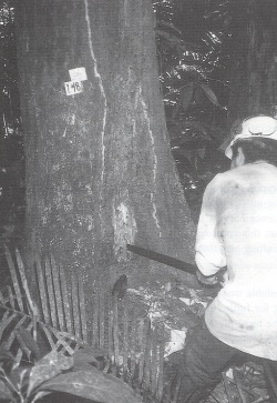
Photo 2. Decay check of trees selected for harvest
If a selected tree proves rotten or if felling of a selected tree would cause too much damage, another non-selected, harvestable tree is chosen for felling in order to meet the desired volume per cutting unit. Each tree where felling is rejected is marked on the map and the occurrence of decay recorded. The latter provides information on the probability of internal decay occurrence in certain areas and certain tree species, which will increase the reliability of planning based on inventory data in the future.
All trees cut during felling operations are marked on the map. Numbers are fixed on each individual log and recorded on data sheets in order to guarantee that no log will be forgotten during the pre-skidding phase. All new information is fed into the computer after felling operations have been finished. A newly generated map of the cutting unit and a list of all trees with corresponding log numbers are given to the crew leader of the pre-skidding crew.
Usually, pre-skidding of logs is planned to be carried out two weeks after the completion of felling operations in order to avoid any disturbance or delays that might arise if both phases were carried out simultaneously within a cutting unit. Immediately after skid trail opening by the pre-skidding crew, logs are concentrated at the skid trail by means of cable. Some logs might be cut into pieces due to their weight. Numbers are fixed to each new log and are registered.
For skidding, which is usually planned two weeks after pre-skidding, the crew leader of the skidding crew receives the map and the list of all trees with corresponding log numbers in order to avoid any loss due to forgotten logs during the skidding phase.
Actual skid trail location and location of landings will be drawn on the map after their establishment since they are considered to be permanent.

Photo 3. Systematic registration of logs prevents timber losses during the extraction phase
As a result of comprehensive land-use planning, the forest management map with elevation contour lines, drawn to a scale 1:20000, shows the following features:
· borders of the permanent forest estate; |
· areas of non-forest land uses; |
· forest cover type, important topographic features, streams and swamps; |
· existing infrastructure and other artificial features; |
· areas where timber harvesting is to be prohibited altogether by law or will be restricted due to the general concept of the sustainable management plan; |
· annual operating areas where harvesting is to be carried out as identified in the forest management plan. |
The areas where timber harvesting operations are prohibited by law are the following:
· streamside buffer zones |
at minimum, 50 m from the sides of a river in case of river width > 10 m; |
at minimum, 30 m from the sides of a river in case of river width < 10 m; | |
· vicinity of water springs |
radius of 50 m from the edge of water springs; |
· steep lands |
Slope gradient > 45%. |
In order to meet the target of about 1/3 preservation forest area of the total F2M forest area (Precious Woods 1995), the following areas have been selected to become preservation areas (biological reserves) based on data and information provided by the general forest inventory as well as aerial photography:
· area of 5000 ha serving as genetic pool; |
· low areas (swamps) where soil damages are unavoidable if ground-skidding systems are used; |
· slopes where systems other than ground-skidding are recommended because of damages and costs. |
A regular grid (north-south/east-west) is laid out over the entire F2M project area forming UTM-blocks (4 km x 4 km) and serves orientation purposes so that all administrative units, compartments, and cutting units, can be conveniently referenced on the ground. All main lines (north-south lines) of the grid were opened and permanently marked by the topographic crew and will be kept open by clearance of undergrowth when necessary.
A topographic crew consists of 6 workers:
1 crew leader with theodolite
2 assistants for field survey and permanent marking of main lines
3 assistants for opening the main lines
Each UTM-block in production forest is subdivided into 10 ha cutting units. Special field crews open help lines 250 m apart running at right angle to the main lines. Starting at the intersection points other lines are opened 400 m apart running at right angle to the help lines to establish the desired grid of 250 m x 400 m rectangles. These are given co-ordinates of letters and numbers so that each cutting unit can be identified. All corner points of each cutting unit are permanently marked. A temporary grid of 50 m x 50 m quadrates, which is needed by the inventory crew, is established within each cutting unit.
A field crew consists of 3 men:
1 crew leader with compass
2 assistants for opening the help lines
A commercial forest inventory conducted during the dry season is planned to be done 2 years before harvesting.
An inventory crew consists of 5 men:
1 crew leader (forester) and
4 assistants (tree identifiers).
The crew members go parallel to one another through the rows of the cutting unit, formed by the 50 m x 50 m quadrates, from south to north and vice versa. They search for trees of commercial interest with dbh > 50 cm. Each tree found is marked; the following parameters are assessed in the field and recorded by the crew leader on data sheets:
· Girth at dbh-height measured by means of a girth measuring tape |
|||
· Botanical identification of tree species |
|||
· Tree location and tree number |
|||
· Quality features, visible defects | |||
· Inclination of tree | |||
· Additional information (measurement height if changed) | |||
A dbh-based formula has been developed by the company to calculate the tree volumes because the measurement of heights is considered imprecise and takes too long.
The following is assessed and recorded in order to provide reliable information for comprehensive planning of harvesting operations:
· Utilisable dead trees including their location |
· Topographic features which may influence harvest planning |
Other tasks of the inventory crew:
· Tree locations and topographic features are drawn on graph paper |
· Climber cutting |
In forests where climbers tend to bridge between tree crowns it is recommended that the climbers be cut well in advance of the felling operation (Dykstra & Heinrich 1996). The climbers die and become brittle; this reduces the chance of a felled tree pulling over neighbouring trees as it falls and facilitates directional felling. Therefore, needed climber cutting is done by the inventory crew at the same time harvestable trees are registered.
Based on data provided by the company, the following performance can be expected for individual activities in field surveying and tree mapping:
individual field activity |
production rate |
establishment of 4 km x 4 km grid |
0.01 manday/hectare |
line cutting of 250 m x 400 m grid |
0.25 manday/hectare |
line cutting of 50 m x 50 m grid |
0.50 manday/hectare |
commercial inventory |
0.33 manday/hectare |
Felling, one of the most hazardous occupations, is carried out by well-trained personnel outfitted with appropriate safety gear and using equipment suitable for the given work task. The final decision on the felling direction of each tree to be harvested is made by the crew leader of the felling crew based on the tree location map and the planned skid trail network. The field situation, with respect to the distribution of future crop trees, existing regeneration, and already felled trees, is also considered.
Measures have been taken in order to meet social, ergonomic, economic and environmental objectives more effectively. The environmentally sound forest harvesting system includes all these considerations:
Objectives |
Measures |
||
safety of felling operations |
· |
personnel fully qualified for the work task, in good health, with ability to recognise hazardous situations, and with personal responsibility; |
|
· |
best qualified chainsaw operators are selected to become crew leaders; |
||
· |
appropriate safety gear and properly maintained equipment; |
||
· |
consistent training in proper felling techniques; |
||
· |
close supervision, |
||
· |
climber cutting prior to harvesting; |
||
minimise damage to residual trees and stand |
· |
a maximum of 40 m³/ha for each cutting unit may be harvested, on average 35 m³/ha are harvested; |
|
· |
a maximum of 80% of the commercial volume found for a particular tree species may be harvested, thus assuring the tree species' continued existence; |
||
· |
final decision on felling direction made in the field; |
||
· |
proper felling technique; |
||
· |
climber cutting 2 years before harvesting; |
||
· |
harvesting map stays with the crew leader; |
||
· |
responsibility of the crew leader for felling direction; |
||
maximise volume of wood |
· |
proper felling techniques; |
|
utilised from each felled tree |
· |
climber cutting 2 years before harvesting; |
|
· |
bucking and grading rules; |
||
· |
close supervision; |
||
facilitate efficient extraction |
· |
harvesting map stays with the crew leader; |
|
· |
directional felling; |
||
· |
climber cutting 2 years before felling; |
||
· |
close supervision. |
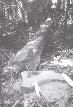
Photo 4. Directional felling, a key for success
In making the final decision on the felling direction, the following has to be considered with respect to:
Extraction |
· |
felling direction at an oblique angle to the skid trail (35°-40° angle range suggested by Dykstra & Heinrich 1996); |
|
· |
felling direction on a skid trail in a straight line position but opposite the skidding direction; |
||
· |
trees should be felled towards the skid trail to reduce the extraction distance; |
||
· |
trees should preferably be felled away from the skid trail if large tree crowns are expected to cause problems for the extraction crew; |
||
· |
extraction should not be disturbed by crowns of trees next to a skid trail; |
||
Residual trees and stand |
· |
trees should be felled toward existing canopy gaps if they are not already too large (e.g. for favourable conditions for natural regeneration of the desired tree species); |
|
· |
damage to potential crop trees and advance regeneration should be avoided wherever possible; |
||
Timber utilisation |
· |
the planned direction of fall should avoid breakage due to falling on obstacles such as tree stumps, logs, or convex terrain. |
The crew leader is responsible for the correct alignment of tree stems with respect to extraction routes. Furthermore, the crew leader supervises and gives advice to the other crew members, alternates with the other chainsaw operators in tree felling, and is responsible for observance of safety precautions by all crew members.
Usually, there was only one chainsaw in use at one time. A second chainsaw was maintained by the crew assistant. The other chainsaw operators support felling preparations.
The analysis of the work studies suggested that in the future a smaller felling crew could be used. The crew and equipment actually observed in the study and the planned crew configuration are shown below:
actual felling crew |
planned felling crew |
|||
1 crew leader/chainsaw operator |
1 crew leader/chainsaw operator |
|||
2 chainsaw operators |
1 chainsaw operator |
|||
1 assistant |
1 assistant |
The productivity of felling operations should not decrease because of the planned changes concerning the felling crew. Since the chainsaw operating time varied considerably among the three chainsaw operators of the observed felling crew and was up to nearly 50% of the total chainsaw operating time for one of the three chainsaw operators; the planned reduction of the crew size should not overburden the remaining crew members.
The extraction of logs is carried out in two phases. The first phase, the pre-skidding of logs, begins with the opening of a single skid trail by means of a crawler tractor assisted by chainsaw. The skid trail is located according to the alignment shown on the map of the cutting unit. For opening a single skid trail an efficiency level of about 8.3 min/100 m skid trail was found in the studies.
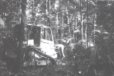
Photo 5. Skid trail opening by the D4 crawler tractor
Turning at the end of the opened skid trail, the crawler tractor moves to the first concentration point determined by the crew leader. This decision is based on the tree and log location map of the cutting unit and the specific field situation. This field decision considers future crop tree locations, regeneration, understory, and obstacles.
The assistants of the pre-skidding crew alternate between pre-setting chokers and pulling the winch line out to the log while the crawler tractor remains on the designated skid trail at all times. The chainsaw operator will crosscut logs and remove smaller trees in the cableway when necessary.
The logs are drawn to the concentration point by means of the winch mounted on the crawler tractor. Since the distance between adjacent skid trails is planned at 100 m, the winching distance will be a maximum of 50 m.
Changes planned to the pre-skidding crew as suggested by the case study are stated below:
actual pre-skidding crew |
planned pre-skidding crew |
|||
1 machine operator |
1 machine operator |
|||
1 crew leader |
1 crew leader/chainsaw operator |
|||
1 chainsaw operator |
2 assistants |
|||
3 assistants |
Changes planned to the equipment used for the pre-skidding of logs as found when the study was carried out are stated below:
equipment used |
equipment planned |
|||
1 D4H TSK crawler tractor with winch |
1 tracked skidder (designed for logging) |
|||
1 Stihl AV 066 chainsaw |
1 Stihl AV 066 chainsaw |

Photo 6. Pre-skidding of logs to the skid trail
The skidding operation is planned to begin one week after completion of pre-skidding within a cutting unit. The logs prepared for extraction at several points of concentration along the skid trail are delivered to the landing by means of wheeled skidder. The skidder remains on the skid trail at all times, since all logs to be skidded are already concentrated at the skid trail and the logs can be easily picked up with the skidder mounted grapple without any need to leave the skid trail.
The study found no need for changes with regard to the skidding crew and the equipment used for the skidding operation:
actual skidding crew |
equipment used |
||||
1 machine operator 1 assistant |
1 Cat 518C wheeled skidder with grapple |
||||
1 Stihl AV 066 chainsaw |
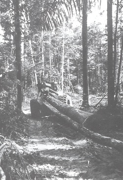
Photo 7. Wheeled skidder equipped with grapple remains on skid trail at all times
Landings are collection areas to which logs are delivered during the extraction process and represent the interface between extraction and transport (Dykstra & Heinrich 1996). Their location and design are carried out during strategic harvest planning, at the same time that the forest roads are located and designed. Therefore, the guiding principles concerning this matter will be treated under forest road planning in chapter 3.7.
At the landing the logs are temporarily stored for the following reasons:
· delays in extraction process if loading activities are carried out simultaneously; |
||
· a one-month buffer to ensure continuous timber supply to the sawmill; |
||
· loss of log weight during period of storage; |
||
· separation of tree species or utilisation groups. |
At the landing the logs are stored in log decks. Softwoods are decked separately from other species. The storage time for softwood species is planned for one month. For all other species a storage time of about two months is planned, since they are not considered at risk of deterioration in quality due to insect or fungal attack.

Photo 8. Log loading for long-distance transport at the landing site
The log loading is carried out by means of a front-end loader; the transport of logs to the company-owned sawmill is by means of the company-owned truck. In general, bucking at the landing is restricted to the occasional cases when the log weight seems to exceed the loader's capacity.
The log transport from the forest to the processing facility is carried out by the company-owned logging truck with a capacity of 35 t. The transport infrastructure is provided by public and forest roads. On average, about 30 m³ of roundwood are transported each trip.
Due to the transportation costs, the average transport distance is an important economic factor. The average transport distance from compartment B to the company's sawmill is 16 km. The average haul distance is 25-30 km for the entire forest property of about 81000 ha. Since there was no long-distance transportation occurring from compartment B during the time of the case study, a log haul from a landing in compartment A was observed.
The average transport time per trip recorded for compartment A was about 1 hour with an average transport distance of 18 km. The time distribution among the work elements was as follows:
Work element |
time |
time shares | |
Travel time unloaded |
25 min |
39 % | |
Loading operation |
14 min |
22 % | |
Load control and fixing load |
2 min |
3 % | |
Travel time loaded |
24 min |
36 % | |
Total time |
65 min |
100 % | |
Travel time unloaded was about the same as travel time loaded.
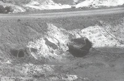
Photo 9. Public road leading through area of wet soil disturbing water regime and causing tree dieback
Environmentally, forest roads are unquestionably the most problematic features of timber harvesting operations. They are complex engineering structures upon which transport efficiency depend and are essential to reliable access to the forest for management and monitoring purposes (Dykstra & Heinrich 1996).
Therefore, comprehensive planning is required for proper location, design, construction, and maintenance of forest roads and subsidiary structures, in order to meet environmental and economic objectives.
Figure 5. Layout of forest infrastructure
To open the annual compartments in the most efficient way, the following are considered:
· forest roads are constructed where access to individual compartments is required but the transportation system as a whole is designed for the entire forest property; |
||
· road density for ground-skidding operations is planned for an average skidding distance of 500-600 m and a maximum distance of 800 m; |
||
· minimise the total length of roads and skid trails to keep costs of construction and maintenance low and to reduce environmental impacts; |
||
· avoidance of difficult terrain and streams, circumventing problem areas such as swamps to minimise environmental problems; |
||
· year-round access to the forest must be provided; |
||
· planned driving speed of 40 km/h; |
||
· minimum storage capacity of 1200 m³ per landing. |
Due to these considerations the following densities are planned:
· Forest roads |
8-9 metres/hectare |
||
· Skid trails |
120 metres/hectare |
Landings are established about 500 m apart on both sides of the forest roads; each landing (40 m x 40 m) is planned to serve as a collection area for timber harvest from four cutting units (see Figure 5).
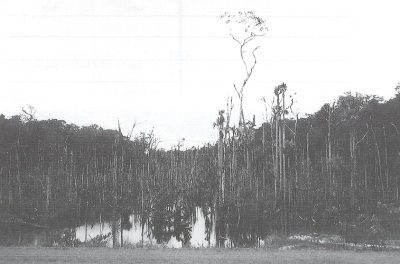
Photo 10. Hollow trees used as culverts
Since the terrain conditions are favourable for forest road construction with regard to site gradients there are no particular rules for culverts. Determination of proper size and spacing of culverts will be decided for each site individually according to terrain condition and runoff rates expected.
Building forest roads in primary tropical rain forests involves clearing vegetation and moving soil in order to create structures capable of supporting heavy vehicles. The machinery needed is hired from local building companies since road construction activities are restricted to the dry season. Company owned machinery would result in high costs due to a long period of non-operation.
Use of the following equipment is planned for the necessary activities in forest road construction:
activity |
equipment |
type |
||
Clearing/first opening |
crawler tractor |
Caterpillar D8 |
||
Grading |
crawler tractor |
Caterpillar D6 |
||
Compacting |
vibration roller |
Dinapac CA15 |
||
Surfacing/shaping |
motor grader |
Caterpillar 120B |
||
To provide year-round access to the forest and to improve the bearing strength of the roads, the base layer will be reinforced by a 10-15 cm thick layer of gravel depending on soil conditions after adequate compaction to form at least a 40 cm thick main body. Gravel will only be spread within the road width of 5 m. A clearing width of 10 m will permit the roads to dry properly after rainy periods. This will avoid the necessity of temporary road closures.
The landings have been constructed by means of the company-owned D4 crawler tractor independent of road construction activities since access to compartment A and parts of compartment B was already provided before harvesting began. The time required for construction of a landing, 40 m x 40 m in size, with the company's D4 crawler tractor was recorded and totalled about 2 hours.
To reduce the total cost of construction, the landings will be surfaced with gravel only if use is planned during the rainy season.
It is planned that landings will be constructed during forest road construction activities in the future. The equipment used for construction will be either a D6 or D8 crawler tractor providing higher performance.

Photo 11. Construction of landing by the company-owned D4 crawler tractor
Unlike the road construction activities, road maintenance is done by company-owned machinery. Necessary repairs such as replacement of inefficient or damaged culverts will be carried out by the D4 crawler tractor; re-shaping and re-surfacing of roads will be done by the Caterpillar 120 B motor grader.
![]()
![]()
![]()
![]()