![]()
![]()
![]()
1.1 The sonar system
1.2 Time varied gain (T.V.G.)
1.3 Acoustic reflecting properties of fish
1.4 The echo-integrator
1.5 Calibration
1.6 Performance check of equipment
An active sonar system is an apparatus used for obtaining information about underwater objects and events by transmitting sound waves and observing the return echoes1 The sound waves produced by sonar systems used for fish detection and biomass estimation are of the same nature as those produced by musical instruments, moving vehicles, machinery, human speech organs, etc. However, the human ear has a restricted range of perception of sound limited approximately to frequencies between 50 and 12000 Hertz (cycles per second, abbreviated Hz). Sonar systems used in fisheries utilize ultra sounds, i.e., the sounds of frequency 12000-500000 Hz, (i.e., 12-500 kHz) which are not detectable by the human ear.
1 An apparatus used only for receiving the sounds generated by underwater objects is called a passive sonar system, which can be utilized in marine biology for detecting sounds generated by fish and other aquatic animals.The users of the sonar system, i.e., sailors, fishermen, and marine researchers have adopted the following terms:
- a sonar system that transmits vertically is called an “echo-sounder” (Fig. 1a).The functioning of both kinds of appartus is the same. Therefore when discussing the basic theory of acoustics and the functioning of acoustic equipment in general we will use the term “sonar system”, and when discussing the practical use of a particular kind of equipment we will use one of the customary names, i.e., “echo-sounder” or “sonar”.
- a sonar system that transmits horizontally is called a “sonar” (Fig. 1b).
The operation of sonar systems used in fisheries work is quite simple (see Fig. 2). Sound is generated in discrete pulses, and after each pulse the system waits for a certain period when a timer (usually part of the display device) activates an electrical transmitter for a fixed period of time. The electrical oscillation of the transmitter is converted mechanically into pressure oscillations (i.e., sound waves) in the water at the vibrating face of the transducer, which continues to generate sound until the timer switches off the transmitter. The result is a sound pulse of a certain duration travelling through the water away from the face of the transducer. Any target (e.g., fish) in the path of this pulse will return an echo to the transducer, which in the waiting mode performs the reverse of its function in the transmitting mode, i.e., it converts pressure oscillations at its face (the echo) into electrical oscillations that are picked up by a receiver, amplified, and converted into some visible sign on the display device, normally a paper recorder oscilloscope screen (see Fig. 2).
The processing of echoes returned by a target requires translating the reflected sound wave that reaches the transducer face, into a form suitable for obtaining information about the target. For example, one important piece of information to be obtained from echo-sounding is the presence or absence of targets. The presence of a target gives a high peak of voltage on the transducer’s terminals, and then at the receiver’s, compared with a low background voltage, and it can be observed as a peak on the oscilloscope display, or a dark mark on the recorder paper (Fig. 4). (The background voltage is the electrical noise or static inherent in the system. It is usually called self-noise).
Assuming that the sound velocity in seawater is a known constant, we can obtain another item of information about the target, namely the distance between the target and transducer (called the range), by measuring the time interval between transmitting pulse and receiving the echo from the target.
From the same simple display units such as a recorder and oscilloscope we can obtain even more information on the target. If it happens that both a small target and a large target of the same acoustic reflecting properties (e.g., two fish of the same species but different in size) appear at nearly the same range it is obvious that from the small target a smaller echo will return than from the bigger one. The small target will produce a rather thin and light echo trace on the recording paper, and a small peak on the oscilloscope, while the big target will produce a very dark echo trace on the recording paper and a high peak on the oscilloscope. But this kind of information is qualitative rather than quantitative. More sophisticated processors and displays have been developed for measuring the quantity of fish detected, particularly echo-integrators.
As mentioned above, information about underwater targets is received in coded form as an echo signal; the main function of a processor is to decode the signal to obtain the required items of information.
The density of acoustic energy, crossing the area normal to the direction of propagation of sound waves in unit time is called the intensity of sound wave.
As we know by experience the intensity of a sound wave decreases with increasing distance from the source of a sound wave. Let us consider the example shown in Figure 3; the observer nearest to the source of sound (distance R1) hears sound of a higher density than the observer who is further from the source (distance R2).
The same law applies to an echo-sounder. Let us imagine that two fish of the same size and species appear within the centre of the transducer’s beam - one fish at the distance R1, close to the transducer, and the other one at the distance R2, further from the transducer (Fig. 4a).
It is obvious that the fish, which is closest to the transducer (distance R1), will produce a higher echo than the other one which is further from the transducer (distance R2).
In order to obtain the echo signal independent of range from the transducer we apply to the echo-sounder, the special signal processing unit which is called the Time Varied Gain amplifier (T.V.G.) (Fig. 4b).
When a sound wave transmitted by a transducer and propagated through a medium meets an object of a density different from that of the medium itself (e.g., a fish in seawater), part of its acoustic energy is absorbed by the target and the remaining part is reflected.
Each target (i.e., reflecting object) has characteristic reflective properties which can be expressed by the ratio between intensities of incident and the reflected sound wave.

where
Ir = intensity of reflected sound wavesThe above ratio expressed in logarithmic units (decibels) is called target strength, which is given by:
Ii = intensity of incident sound waves
TS = 10 log t S (dB)
The other magnitude which characterizes the acoustic properties of the target is its equivalent cross section, and can be expressed as:

Experiments with fish species with swim bladders have shown that about 85 percent of the sound energy is reflected by the swim bladder. Species lacking swim bladders reflect less acoustic energy than those with swim bladders. In general, the reflecting directivity pattern, and the relationship between fish size and scattering cross-section, can be determined for species in both categories.
The acoustic properties of fish as they affect estimates can be summarized as follows:
1. The target strength (or scattering cross-section) of a fish has a directivity pattern, i.e., the relative intensity of sound reflected by a fish back to the source depends on the “aspect” of the fish, i.e., its orientation relative to the source (see Fig. 5). The directivity pattern depends in general on the anatomy of the fish, its overall size, and the dimensions of the swim bladder relative to the wave length.2. For a given species of fish (i.e., fish of a certain anatomy) and for a given wavelength (or frequency of sound) there is a close relationship between the target strength (or equivalent cross-section) and the size of the fish: the larger the fish, the larger its target strength or equivalent cross-section.
3. In the absence of a large variation in the size of fish of a given species, we can approximate the relationship with a simple proportionality between the equivalent cross-section and weight per fish:
s ~ w
The echo-integrator is a special signal processor which integrates echo signals appearing on the output of an echo-sounder with T.V.G. (i.e., range independent amplifier).
The detailed description and derivation of functioning of an echo-integrator is beyond the scope of this chapter and one can find profound treatment of this subject in the manuals of applied fisheries acoustics (see references).
The deflection of the echo-integrator is proportional to the density of biomass of sampled fish per unit area which can be expressed as:

where
It has been proved by various experiments that the above integrator equation is valid for a given species of fish, if the variation in the sizes of fish is not too large. (The scattering cross-section of fish of a given species can be taken as approximately proportional to the weight per fish in this case). However, the integrator output signal might give a good indication of the total biomass density of fish in a survey area even when a number of similar species of different sizes are surveyed.: average density of biomass (t/n.mi2)
: deflection of the echo-integrator per ESDU (Elementary Sampling Distance Unit)
C: “calibration constant” of the integrator
Hence, the estimated biomass in the surveyed area can be expressed as:
where
A: survey area in n.mi2
In order to obtain a quantitative estimate of fish surveyed with a sonar system consisting of an echo-sounder with T.V.G. and an echo-integrator, we have to determine the value of the proportionality coefficient in the echo-integrator equation, i.e., the value of “C”.
One of the most reliable methods for determining the value of the calibration constant is direct calibration on live fish. This method was first described by Johannesson and Losse (1977).
Let us consider an acoustic system consisting of an
echo-sounder with T.V.G. and an echo-integrator as a “black box” with
an input, biomass density  ,
and an output, integrator
deflection
,
and an output, integrator
deflection . We do not know
what is inside the black box, but the relationship between input and output can
be found experimentally by measuring both at various input levels (Fig.
7).
. We do not know
what is inside the black box, but the relationship between input and output can
be found experimentally by measuring both at various input levels (Fig.
7).
Summarizing, the concept of the direct method of calibration
on live fish lies in measuring the value of the integrated echo signal
,- caused by a known biomass
density of fish and then
determining the relationship between
and
from the results of several
such experiments. According to the integrator equation we should obtain a
proportional relationship between
and
.
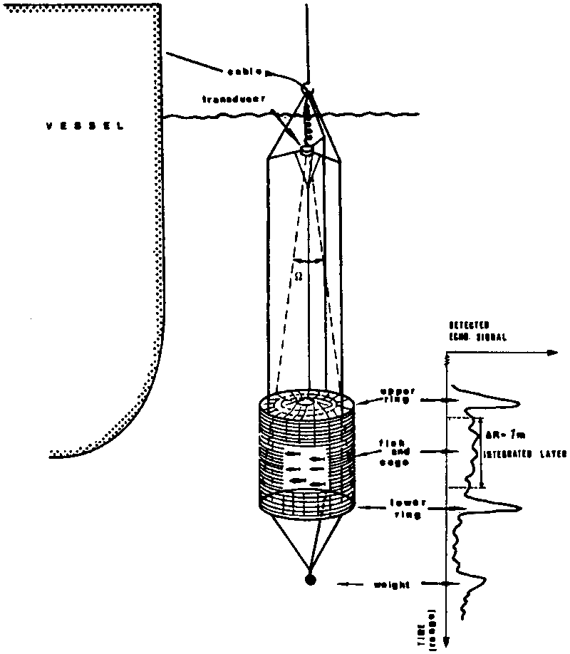
The arrangement for calibration on live fish is shown in Figure 8, A known quantity of fish is impounded in a special cage, which is placed below the transducer at the centre of its beam.
If a number of experiments are performed with different densities of fish, the value of the calibration constant can be estimated by fitting a linear regression line to the experimental values of the variables d (biomass density) and M (integrator deflection).
d = AM + B
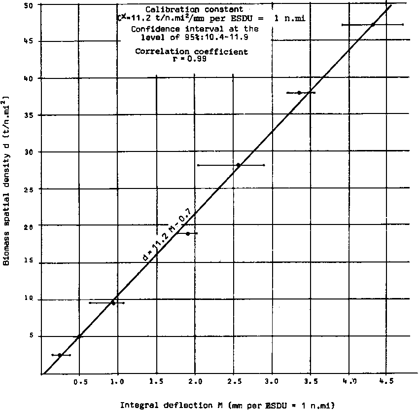
A = C = slope of the regression line, equal to the calibration constant valueFigure 9 shows an example of the results of direct calibration on anchoveta (Engraulis ringens) with a 120 kHz echo-sounder by Johannesson et al., of the FAO/NORAD/IMARPE Acoustic Training Centre in Lima. The results of the experiments are plotted on the graph, i.e., integrator readings (M) versus biomass density (d). The first measurement of echo-integrator deflection was taken with the cage empty, i.e., without fish. For each density of fish a number of integrator readings were then recorded and the mean value was calculated. The mean integrator deflection for a given biomass density, reduced for the reading from the empty cage, is denoted on the graph by a thick point. The lines parallel to the (M) axis through the points show the variation of integrator deflection at each density of fish.
B = intercept of the regression line
The regression line and the calibration constant value presented in the example of Figure 9 were estimated according to the procedure described above. The calculated value of the intercept of the regression line (B = 0.7) is not significant and can be considered zero for practical purposes. In this experiment the regression line fits well (correlation coefficient r = 0.99). However, it can happen that the value of the intercept of the regression line is large, and the regression line does not fit the empirical data well. This indicates that the assumed physical model of calibration does not correspond to reality. It can happen if the cage is not placed in the centre of the transducer’s beam (the current diverts the cage from its central position, or the cage is not aligned within the transducer’s acoustic axis), or if the fish are not uniformly distributed within the volume of the cage.
The behaviour of the fish and their condition (especially any mortality) must be observed during the experiments (for instance by a diver or underwater camera). The calibration should be carried out after a few hours acclimating the fish, first in the keep-net and then in the cage. A purse-seine can be used as a keep-net for the fish, since it provides quite a good semi-natural pen.
The central position of the cage can be controlled by observing on the oscilloscope the level of echo signals from reference targets (spheres) placed at the centre of the cage above the upper ring and below the lower ring.
This method of calibration has limitations due to fish behaviour, which in turn depends on species and on density of fish in the cage. According to observations by Johannesson et al., (Unpublished data of experiments at the FAO/NORAD/IMARPE Acoustic Training Centre, Lima), Burczynski and Azzali (1977), and Rijavec and Burczynski (1977), for a certain range of fish densities in the cage, the integrator deflection and the spatial density of fish are proportional but not for all densities. A graph of the patterns of observations is shown in Figure 10.
a) Low densities of fish: if the fish do not school but distribute themselves uniformly throughout the cage, there is direct proportionality between the echo-integrator deflection (M) and the biomass density (d) (dotted line on the graph). If the fish school at the centre of the cage, the echo-integrator readings will be higher than expected from the proportionality law (upper continuous line on the graph). If the fish school at the edge of the cage, the echo-integrator readings will be lower than expected (lower continuous line on the graph). All three cases are predictable from the directivity pattern of the transducer.Most fish aggregations found in natural conditions, i.e. during surveys, can be classified as having low and medium densities. Hence, the results of the calibration on medium and low densities, if variations from proportionality law are not observed, can be directly applied for fish biomass estimates.b) Medium densities of fish (fish uniformly distributed within the volume of the cage). A proportional relationship is observed between echo-integrator deflection (M) and biomass density (d).
c) High densities of fish: saturation of (M) against (d), a proportion of the fish are swimming horizontally, the remainder, vertically and with the various tilt angles due to high packing density; possible effect of increased attenuation in the environment which consists of seawater and fish bodies and possibly also a secondary reflection effect between individual fish.
According to the discussion on basic laws of acoustics the value of the echo signal appearing at the output of a sonar system depends, on the one hand, on fish parameters (FP) and, on the other, on sonar system parameters (SSP) (Fig. 11). Hence, the estimated value of the calibration constant “C” is a function of (FP) and (SSP):
C = f [(FP), (SSP)]
In other words, the value of the calibration constant obtained by experiment is valid only for the given species of fish, the given size distribution of fish and the given set of acoustic equipment.
The technical parameters of acoustic equipment can change with time2. On the other hand, calibration on live fish is a costly and time-consuming operation, and it can be carried out under special favourable weather conditions (i.e., lack of swell and underwater current). To avoid repeating a calibration, it is best to ensure that estimated fish parameters (FP) from a “master experiment” can be applied for estimating the value of the calibration constant for subsequent acoustic surveys on a given fish species and this is possible provided the actual sonar system parameters (SSP) are known.
2 Examples: The efficiency of a transducer decreases when the echo-sounder is not used for a long period of time (especially if a vessel is in a harbour), because of the covering of the transducer’s radiating face by shells and marine vegetation (it happens in tropic waters quite fast); the gain of an amplifier or transmitted power can be significantly changed when replacing electronic components of instruments (e.g., transistors), etc.Summarizing, we have to measure the values of the parameters of a sonar system (SSP) in order to check that the equipment is working properly, i.e., according to technical specification (if not it must be adjusted), and in order to be able to revise the previously estimated value of the calibration constant if the values of SSP have changed.
The procedure of measuring the SSP is called a “performance check” or “acoustic and electronic calibration of the equipment”.
The performance check of equipment should be a routine operation for each survey.
Usually calibration procedures are carried out with an external transducer, while echo surveys are carried out using the vessel’s hull-mounted transducer. This procedure is recommended for convenience of operation with the cage and the live fish.
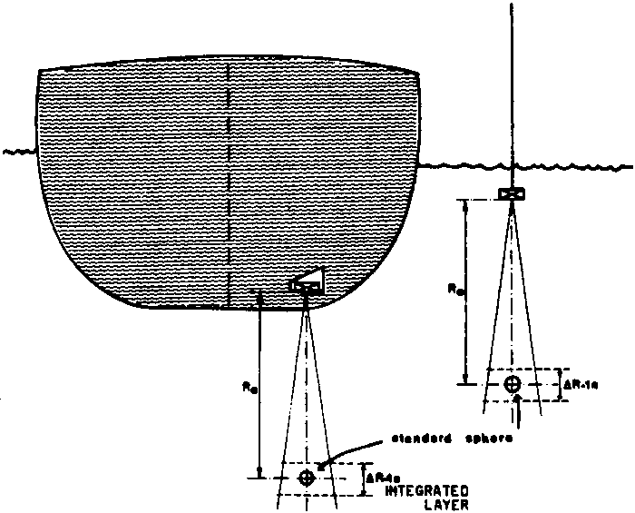
The inter-calibration of the two transducers can be done by measuring the integrator deflection for both of them, produced by a standard target i.e., a sphere placed in the centre of the transducer’s beam2 and in the middle of the integrated layer (Fig. 12). The calibration constant for the vessel’s transducer can then be calculated as follows:
where
Ce = the value of calibration constant obtained from experiments on live fish with the external transducerThe inter-calibration of transducers with a standard sphere target (Fig. 12) has been proved by Johannesson (FAO/NORAD/IMARPE Acoustic Training Centre in Lima) to be a method giving reliable results. The value of the calibration constant obtained from results of calibration experiments with a given species, can be recalculated for any other set of equipment installed on the vessel, if the estimated value of “C” is referred to the measurements on a standard target. Measurements of the integrator deflection from a standard target should be included as a routine procedure in the performance check of the equipment.Me = the integrator deflection for a period of time corresponding with ESDU = 1 n.mi for the external transducer
MV = the integrator deflection for a period of time corresponding with ESDU = 1 n.mi for the vessel’s transducer
2 Examples: The efficiency of a transducer decreases when the echo-sounder is not used for a long period of time (especially if a vessel is in a harbour), because of the covering of the transducer’s radiating face by shells and marine vegetation (it happens in tropic waters quite fast); the gain of an amplifier or transmitted power can be significantly changed when replacing electronic components of instruments (e.g., transistors), etc.
Figure 1 Detection and location of fish by (a) echosounder (b) sonar
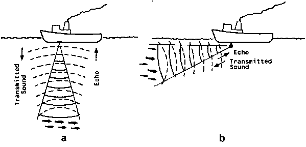
Figure 2 Functioning of an active sonar system
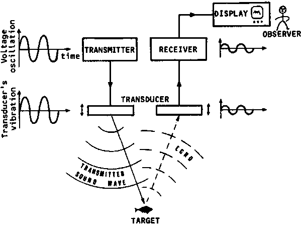
Figure 3 Sound waves generated by a gong
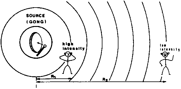
Figure 4(a) Display of echoes produced by two single targets (a) echosounder without TVG
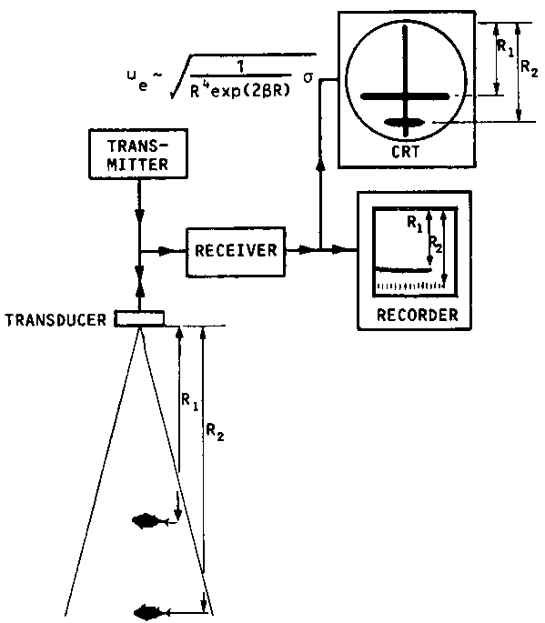
Figure 4(b) Display of echoes produced by two single targets (continued) (b) echosounder with TVG
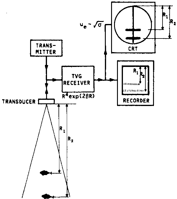
Figure 5 Two-plane polar diagram of the target strength (equivalent cross-section) of fish versus direction of propagation of sound wave for cod of length L = 69 cm: (a) coordinates, (b) diagrams for frequency f = 97 kHz, (c) diagrams for frequency f = 30 kHz (diagrams constructed according to measurements by Haslett, 1977)
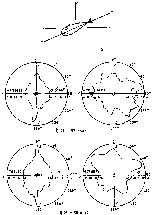
Figure 6 Average surface area sampled by an echo integrator
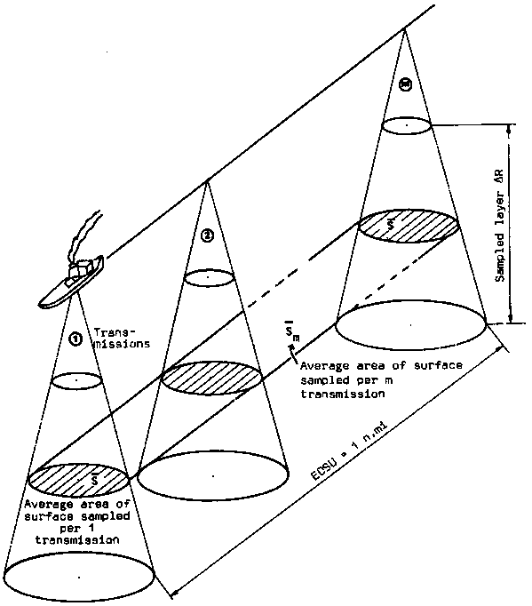
Figure 7 Concept of calibration on live fish: (a) BLACK BOX, (b) INPUT/OUTPUT relationship
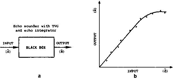
Figure 8 Arrangement for calibration on live fish
Figure 10 Observed echo integrator readings at low, medium and high biomass densities
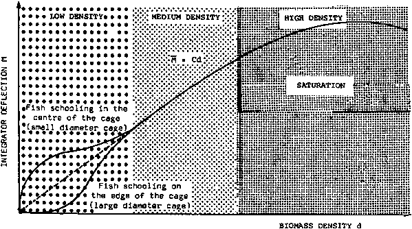
Figure 11 Schematic relation between Fish Parameters (FP), Sonar System Parameters (SSP) and the output signal of the sonar system
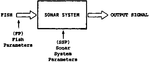
Figure 12 Inter-calibration with a standard target
![]()
![]()
![]()