![]()
![]()
![]()
The layout of a floating farm in Singapore which follows the PPD design is one with 32 raft units, each 5m × 5m (Figures III/1 & III/2). There may however be variations to this from farm to farm. For example, there are farms with smaller raft units of 2m × 2m or 3m × 3m or even a combination of units. This depends on the need of the farm.
2.1 Materials
a The materials required for the construction of a floating farm with 32 (5m x 5m) raft units are listed in Table III/1:
| Material description | Unit | Est. quantity | ||
| 1 | Timber, kapur (Drvobalanoos aromatica) | |||
| a | 101 mm (4") × 76mm (3") × 7m | pc | 320 | |
| (0.054m3/pc) | (17.28m3) | |||
| b | 203 mm (8") × 25mm (1") × 7m | pc | 180 | |
| (0.035m3/pc) | (6.4m3) | |||
| c | Plywood, 2.42m (8') × 1.21m(4') | pc | 10 | |
| 2 | Galvanised iron parts | |||
| a | Bolt-nuts sets | set | ||
| 101mm (4") × Ø12.7mm (1/2"), B.S.W. | 30 | |||
| 127mm (5") × Ø12.7mm (1/2"), B.S.W. | 300 | |||
| 203mm (8") × Ø12.7mm (1/2"), B.S.W. | 1200 | |||
| 228mm (9") × Ø12.7mm (1/2"), B.S.W. | 300 | |||
| 304mm (12") × Ø12.7mm (1/2"), B.S.W. | 20 | |||
| b | Mail, 75mm (3") length | kg | 40 | |
| c | Washers | |||
| Square, 50mm (2") × 50mm (2") | pc | 3000 | ||
| Round, to fit (a) | kg | 1000 | ||
| 3 | Mild steel parts | |||
| a | Bracket, corner (Figure III/13) | no. | ||
| Type A | 64 | |||
| Type B | 64 | |||
| b | Pipe, internal Ø 38mm (2") × 3.1m | no. | 128 | |
| (Figure III/I) | ||||
| c | Joint, swivel (Figure III/1) | set | ||
| Type A | 18 | |||
| Type B | 4 | |||
| d | Plate, 865mm(34") × 75mm (3") × 12mm (1/2") thick | pc. | 160 | |
| 4 | Other metal materials Zinc sheet 76cm × 46cm | pc. | 24 | |
| 5 | Floatation system | |||
| a | Drum, plastic, 910mm (36") ht × Ø 580mm(23") | no. | 400 | |
| b | Paint, antifouling, 22.5 litre/tin | tin | 6 | |
| c | Brush, Paint, 150mm (6") | no. | 10 | |
| d | Resin, polyester, 20 kg/tin | no. | 10 | |
| e | Thinner, lacquer, 4.5 litre/tin | tin | 10 | |
| f | Catalyst, peroxide | litre | 10 | |
| g | Rope, roll of 220 m polyethylene, Ø5 mm (115") | roll | 30 | |
| 6 | Anchoring system. | |||
| a | Thimble, | no. | 30 | |
| b | Shackle, | no. | 30 | |
| c | Spike, | no. | 6 | |
| d | Rope, polyethylene, Ø01mm(4") Roll of 220m | roll | 4 | |
| e | Rope polyethylene, Ø6mm (1/4") Roll of 220m | roll | 4 | |
| f | Anchor, concrete block, 2–3 ton/blk | no. | 12 | |
| 7 | Tools and Others | |||
| a | Hammer, clawed | no. | 6 | |
| b | Saw, | no. | 3 | |
| c | Spanner, adjustable | no. | 10 | |
| d | Hacksaw | no. | 2 | |
| e | Axe | no. | 2 | |
| f | Chisel | no. | 6 | |
| g | Tape, measuring | no. | 2 | |
| h | Oil, wood preservation, 5 litre/tin | tin | 25 | |
| i | Light pilot with white flashing lamp and Victor batteries (each 6V) | set | 4 | |
| j | Paint, red lead primer 4 litre/tin | tin | 8 | |
b The materials required for the construction of a 5m × 5 m raft unit are listed in Table III/2 below :
| Material description | Unit | Est. quantity | ||
| 1 | Kapur (Dryobalanoos aromatica) timber: | |||
| a | 101mm (4") × 76mm(3") × 7m | pc | 9 | |
| b | 203mm (9") × 25mm (1") × 7m | pc | 8 | |
| 2 | Galvanised iron parts | |||
| a | Bolt-nuts sets | set | ||
| 203mm (8") × Ø 13mm (1/2") | 40 | |||
| 127mm (5") × Ø 13mm (1/2") | 16 | |||
| b | Nails, 75mm (3") length | kg | 0.7 or mor | |
| c | Washers | |||
| Square, 50mm (2") × 50mm (2") (Figure 10, this handout) | pc | 100 | ||
| Round, to fit (a) and (b) | kg | 0.16 or mor | ||
| 3 | Mild steel parts | |||
| a | Bracket, corner (Figure III/13 | no. | ||
| Type A | 2 | |||
| Type B | 2 | |||
| b | Pipe, internal Ø 38mm(2") × 3.1m (Figure III/1) | no. | 4 | |
| c | Plate, 865mm(34") × 75mm(3") × 12mm(1/2") thick | pc. | 2 | |
| 4 | Floatation system (Figure III/7) | |||
| a | Drum, plastic, 910mm(36") ht × Ø 580mm(23") | no. | 8 | |
| b | Rope, polyethylene Ø5 mm (115") | mtr | 40 | |
| 5 | Tools and Others | |||
| a | Hammer, claw | no. | 2 | |
| b | Saw, | no. | 2 | |
| c | Spanner, adjustable | no. | 2 | |
| d | Hacksaw | no. | 2 | |
| e | Axe | no. | 2 | |
| f | Chisel | no. | 2 | |
| g | Tape, measuring | no. | 2 | |
| h | Oil, wood preservation, 5 litre/tin | tin | 1 | |
2.2 Marking and preparing timber for bolt fittings
Based on those specifications given in the layouts of a 32-5m × 5m unit and a single 5m × 5m unit raft structure in Figures III/1 and III/2 respectively, wooden beams of kapur timber, each measuring 101 mm × 76 mm in cross section and 7 m in length are carefully and accurately measured and marked. Holes of Ø 14mm (9/16") are drilled in the marked places.
Carpentry procedure for a single 5 m × 5 m raft frame unit is covered in Practical III/1.
2.3 Float preparation prior to raft assembly
A floating fish farm comprising 32 (5m × 5m) raft units, a central walkway and floating but would weigh about 26 tonnes. Four hundred plastic drums (Figure III/7) each of about 200-litre capacity is estimated to have a buoyancy of about 56 tonnes, with 70% displacement and is the optimal number required to float the whole farm.
2.4 Anchoring system and its preparation
Anchoring can be considered to be the most important aspect of floating farm construction because it is responsible for the farm's position and safety. Anchoring involves the sinking of suitable weights connected by ropes to the floating structure and placed at strategic points to hold down the farm.
Anchors can be the conventional sort used by ships or heavy objects such as metal blocks and containers filled with concrete; concrete blocks or even wood piling on the sea bed.
In our case, trapezoidal concrete blocks (Figure III/S) are selected for their cost and ease of fabrication. Fourteen blocks (Figure III/9) each of 2–3 tonnes are required to hold down a floating raft comprising 32 interlocked raft units to be located in the East Johore Strait, Pulau Ubin area.
Eight anchor blocks are placed on the side of the farm facing the ebb tide, and 4 on the side facing the flood tide. This is because the ebb tide current is stronger than the flood tide.
Two anchors are located in the mid-section of the other two sides.
As a guideline, anchor blocks should have a total weight which is 1.5–2 times the weight of the whole floating structure. In this instance, the estimated 26-tonne structure is anchored by 28–42 tonnes of anchor (1.1–1.6 times). However, this depends also on farm location and sea conditions.
2.5 Installation of the anchoring system
The rope system (Figure III/11) secures the anchor blocks to the raft. Polyethylene rope (0 45 mm) is used. Each end is eye-spliced (Figure III/12) with the appropriate thimble and shackle for holding. A brightly coloured float or buoy (encased in a rope for protection and ease of operation) connects the end point of the anchor rope just below water surface. From the float/buoy another similar rope leads to the raft unit. This method is more secure as it allows easy identification of anchor location should the anchor rope snap.
To install the anchors, it is important to mark the farm boundary with small floats as this is where anchors are supposed to be dropped. A plumb line is used to measure water depth at low end high tides (neap and flood tides). The small markers, each consisting of several bricks for weight, a rope and a float, are dropped at the positions where the anchors should be. Anchor blocks are then transported by barge or pontoon to the site. One end of the anchor rope is shackled to the anchor block ring while the other end is shackled to the float/buoy. The block is lifted by crane and lowered at the marked position. This is continued until all anchors are positioned.
The procedure for installing the anchoring system is covered in Practical III/2.
2.6 Fabrication of metal joints, plates, brackets and pipes
Figures III/1 and III/13 show the different types of metal joints, brackets, plates and pipes used in a floating farm. These are parts which connect the raft structure, reinforce extended timber beams, and provide for holding of metal pipes.
2.7 Assembling the raft unit
Assembling operation is done on shore, usually the beach for convenience. Wooden beams can be joined by bolt-nuts with the aid of clamps. There are 4 main sections to the raft structure (Figure III/4), each comprising 8 raft units of 5m × 5m.
Assembling is therefore done part by part, that is in segments of 4 raft units. Two of these segments would then form one section of 8 raft units.
Plastic drums which have been treated are attached to the raft segment to float the structure and metal brackets and joints fixed.
The central walkway, which basically comprises two parallel long beams, and several short horizontal beams is also assembled (Figure III/14).
Timber planks, each of 203 mm × 25 mm × 7 m, are used to cover the edges of each raft unit or frame, to serve as walkways or platform for various work operations.
A wooden hut (Figure III/1) can be constructed when the raft structure is being assembled or during the construction of central walkway.
At around the same time when the floating raft segments are being assembled, the anchorage system will have to be set at the farm site. The floating raft can then be towed and aligned and rope connections made to the anchor floats.
Finally, metal parts like the bolt-nut sets, brackets and plates should be painted with lead primer followed by 2 coats of anti-corrosive paint to protect against corrosion. The bolt-nuts sets are further sealed with good quality bitumen sealant. All timber should be painted with wood preservative oil.
The detailed procedure for raft assembly is covered in Practical III/2.
Maintenance can be time consuming and laborious because of fouling and corrosion. The work involved is summarised as follows:
3.1 Floats
Encrustating or fouling organisms (Figure III/15) contribute most to weight and subsequently buoyancy loss. Boring organisms such as the teredo worm are responsible for leakages. Such fouling will have to be routinely removed to maintain good buoyancy and extend drum float life. Antifouling paints lose their effectiveness within 2–3 months.
Maintenance is therfore directed at keeping to cleaning and treatment schedules for the floatation system, and this begins 3–4 months after initial immersion. During this time, the drum floats will be turned 180° to even out the bio-fouling. The fouling organisms exposed to air would die off and although some would fall away, still require manual scraping for proper removal. By the sixth to eighth months, the drums would have been turned through 360° and have to be removed for total cleaning and treatment. This involves manual scraping and repainting with antifouling paint (Figure III/16). The cycle then begins all over again. It is estimated that by this method, 70–80% of the floatation system should last about 8 years or more. Other minor maintenance involves cap resealing and plugging up of small leaks.
The procedure for changing the float unit is covered in Practical III/3.
3.2 Timber structures
Timber parts need re-painting with wood preservative every 1-1 1/2 years. This is standard practice. As timber may crack with time, dismantling of the beams and replacement may be necessary.
3.3 Metal parts
Bolt-nuts need replacement once every 1–3 years, depending on their condition and how well they have been protected initially;
Metal brackets will last from 1–4 years, after which replacement is necessary. General maintenance includes re-painting of the brackets whenever necessary;
Movable joints need to be greased every week to ensure free movement. Replacement is required every 4–5 years;
Metal pipes will normally last 1–2 years, after which replacement is required. Routine painting of the pipes with anti-corrosive may also be necessary from time to time;
Galvanised nails should be replaced once corroded. This is usually on a yearly basis.
3.4 Anchoring system
Fouling organisms on the ropes cause them to sag with time. This puts a strain on the farm. These organisms should therfore be removed regularly. The frequency of cleaning depends on the farm location, but as a rule this is done once every 4 months for fish farms in the Pulau Ubin area off Singapore.
Manual cleaning is time-consuming and tedious. A metal device on a wooden set-up on board a boat helps to remove fauling more efficiently. The device helps to remove fouling by resting the anchor rope on its crook and clears off the encrustations when the boat moves (Figure III/19). The cleaned rope is then beaten in water to remove stubborn encrustations. Ropes can last 3–5 years, after which a complete change is required for safety purposes.
Anchor floats need to be replaced (Figure III/20) every 4–5 months with some cleaning in between. Other maintenance required are replacement of shackles and thimoles, inspection of metal parts mainly sheckles and thimbles by divers every 2–3 years.
The procedure for anchoring system maintenance is covered in Practical III/2.
1 Objective
To construct the basic 5 m x 5 m raft unit of a floating fish farm.
2 Materials
See Table III/2
3 Procedure
3.1 Preliminary preparation of timber.
3.1.1 Marking
Make markings on the 76mm × 7m side of the wooden beam which is 101mm × 76mm × 7m. This side should face upwards. The markings are for bolt and nut positions.
Make the first mark 0.56 m from the left end of the beam (Figure III/3) and the second, 5 m from this. Mark also the mid-point opf the 5 m length. Make the final marking at 0.56 m from the 5 m mark and saw off the beam to obtain a length of 6.12 m. With markings at 0, 0.56, 3.06, 5.56 and 6.12 m starting from the left end.
Make similar markings on 5 wooden beams. These are the top beam of the raft unit.
Mark another set of 4 wooden beams (underside beams of the raft unit) as in (b) and (c) but without the mid-point mark for the 5 m length. The beam is a length of 6.12 m with markings at 0, 0.56, 5.56, 6.12m starting from the left end, (Figure III/4).
3.1.2 Drilling
Holes are drilled in the markings made for the bolt-nut sets to be fitted.
Use a hand or electrical drill fitted with 9/16" drill bit to make the holes.
Scoop out a square depression of 5cm × 5cm × 2cm (depth) (Figure III/5) around each hole with a chisel and hammer.
3.1.3 Timber treatment
Paint all timber with two coatings wood preservation oil. Allow the timber to dry.
3.1.4 Preparation of floats
This will be carried out during III/2.3 “Floatation system, installation.”
3.1.5 Preparation of anchors
This will be done as in III/2.5 “Installation of the anchorage system”.
3.1.6 Assembling the raft unit
Gathering the materials
Collect the prepared timber, floats and anchors and move them to the beach.
Raft frame construction
Collect the prepared timber, floats and anchors and move them to the beach.
Eight wooden beams prepared as in (3.1) are bolted together firmly by 20 bolt-nut sets and according to the positions as shown in Figure III/6, making a double-beamed square wooden frame.
Note that 4 wooden beams are placed cross-wise and on top of the other 4 wooden beams.
Seal the 5cm × 5cm × 2cm depressions in the wood with bitumen sealant.
Align the central wooden beam parallel to the top beams and the mid-points of the beam below (underside). Bolt as shown at the 4 points on the beams below.
Fix 4 metal brackets of the ‘A’ and ‘B’ (laterally inverted) tyres to the corners of the raft frame, with a 125mm (5") bolt-nut set, using a drill with 9/16" bit to bore the necessary holes.
Move the raft frame to the beach where the water depth is no more than 0.5 m at high tide.
Insert 8 floats systematically under the underside beams, fitting them along the 2 parallel and opposite gaps (each 0.56 m × 6.12 m) at 4 floats per gao.
Tie each float to the raft unit with Ø 5mm polyethylene rope.
Nail suitably-sized timber planks cross-wise at about 15cm space intervals along the double beams framing the raft unit to form a walkway.
This completes the raft unit which is ready for floatation.
Exercises
Note the markings on the wooden beam that is used in the construction of the raft unit.
Note the positions of the floats and the level of the water surface in relation to the float.
Note how the raft unit is assembled and the need for teamwork.
Design and plan for the construction of a wooden raft unit suitable for a 3m × 6m × 3m (depth) netcage. Show in your drawings, timber markings, float positions and what the final structure should look like. List all the materials and their quantity required.
Consider the design and plan for constructing a hexagonal raft unit which has a ‘diameter’ of about 4 m.
Practical III/1
Name:
Country:
Date:
Questionnaire
Raft frame construction and maintenance
| 1 | Are floating rafts used for fish farming in your country? | ||
| [ ] Yes | [ ] No | ||
| 2 | What are the materials used in the construction of floating raft? | ||
| [ ] wood | [ ] bamboo | [ ] PVC pipe | |
| [ ] metal | [ ] Others | ||
| 3 | What is the shape of the floating raft? | ||
| [ ] square | [ ] rectangular | [ ] round | |
| [ ] hexagonal | [ ] Others | ||
| 4 | How are the rafts set? | ||
| [ ] singly | [ ] connected | ||
| 5 | How are the rafts connected together? | ||
| [ ] in single rows | [ ] in several rows | ||
| 6 | To whom do the rafts belong? | ||
| [ ] commercial | [ ] government | [ ] Others | |
| sector | |||
| 7 | Is the construction of raft units/floating farms directly relevant to your work? | ||
| [ ] Yes | [ ] No | ||
| 8 | Would you like to be part of a discussion group on raft unit and floating farm construction? | ||
| [ ] Yes | [ ] No | ||
1 Objective
To study the construction, installation and maintenance of the anchorage system of a floating farm.
2 Procedure
2.1 Construction of a concrete anchor block (Figures III/10 A-B)
Position the galvanised chain and metal bar in a half oil drum which comes from cutting a 200L metal drum cross-wise into two.
Erect a wooden structure to support the chain and metal bar, which form the grip to the anchor block.
Prepare concrete as follows:
Preparation of concrete
Man washed sand, coarse gravel and cement and water at a ratio of : : : *3 by weight.
For one half-drum, mix 3 baskets*1 of sand, 5 baskets of gravel*2 and 30 kg of cement with *4 litres of water.
While pouring the prepared concrete into the half-drum, use a board mounted on a stick to compace the soft concrete.
Fill to the half-drum with concrete.
Cover the top portion of drum with paper to pre art falling objects from embedding into the concrete.
Let the concrete stand for 2–3 days to set. The block should weight out 200 kg. Larger blocks can be made in a similar manner.
* Fill in the blanks
* 1 kg/basket
* 2 kg/basket
* 3 : : ratio of sand : coarse gravel : cement
* 4 litres water to mix.
2.2 Installation of the concrete anchor block
Drop small markers, each consisting of several bricks for weight, a rope and a float, at the positions where the anchors should be;
Transport the anchors on a boat to the designated position in the sea;
Tie the anchor with an anchor rope (0 25 mm) and float;
Drop the anchor at its designated position;
Tie the anchor to the raft (Calculation for length of anchor rope to be used is shown below):
Calculation of anchor position
The length of the anchor rope should be 3–5 times the water depth at High Water Spring Tide (HWST).
| Example: | Water depth at HWST (AC) = 9m | |
| Length of anchor rope (BC) | = (3 × 9m) to (5 × 9m) (anchor to raft) | |
| = 27m to 45m | ||
| X | = 36m | |
| Anchor position (AB) | = 34.9m, calculate by | |
2.3 Maintenance of the anchorage system
2.3.1 Changing of the anchor float (see Figure III/20).
Untie the anchor rope from the raft structure.
Lift up the anchor float together with part of anchor rope with a hydraulic winch (on the boat).
Carefully remove the anchor float.
Scrape off the fouling organisms around this portion.
Tie the anchor rope to the new float.
Lower the anchor float as far into the water as possible and let go to sink it to the sea bottom.
Readjust the anchor rope to obtain a suitable slack.
2.3.2 Cleaning of the anchor rope (see Figure III/19)
Set up the cleaning device (which is a wooden piece with 2 bolts mounted on) on a boat.
Lift up a portion of the anchor rope and rest it on the cleaning device.
Move the boat and beat the rope to remove encrustations against the bolts.
3 Exercises
3.1 Note how the marking of the anchor position is made.
3.2 Note how the anchor rope is tied to the float and the concrete block.
3.3 If you are to position a raft structure at a site where water depth is 11 metres during high water spring tide, what length of anchor rope should you use and why is this length necessary?
Practical III/3
Name :
Country:
Date :
Questionnaire Anchorage System: Installation and maintenance
If there are floating farms or structures used in fish farming in your country, please answer (1) - (4):
| 1 | What sort of anchors do the farms/structures have? | |
| [ ] concrete blocks | [ ] wood pillings | |
| [ ] metal sinkers | [ ] ships anchors | |
| [ ] Others | ||
| 2 | What is the shape of the anchor? | |
| [ ] round [ ] square | [ ] conventional | |
| ships anchor | ||
| 3 | What is the estimated weight of each anchor used? | |
| [ ] Up to 0.5mt | [ ] >0.5–1 mt | |
| [ ] >1mt–2mt | [ ] >2mt | |
| 4 | What is the size of raft unit (s)? | |
| m × m | ||
| 5 | How many anchors are used ? | [ ] nos. |
| 6 | Would you like to be a member of a group to discuss further anchorage systems for floating farms? | |
| [ ] Yes | [ ] No | |
1 Objective
1.1 To treat, install and maintain the floats of fish farm.
1.2 To observe fouling of the floatation system of a fish farm.
2 Procedure
2.1 Treatment of plastic floats
Drain the dregs of the plastic drum which is the floatation unit of the farm. Wash it thoroughly with fresh water.
Tighten the caps with a wrench.
Seal the cap with fibreglass according to the to the procedure below:
Sealing off the drum float
To about 200 ml of fibreglass resin are added 2–3 drops of peroxide hardener. One layer of mat is spread over the caps of the drum and covered with the prepared resin which is absorbed by the mat. Another layer of mat is applied, followed by resin. The sealing is left overnight to dry and harden.
Paint the float with a single coat of antifouling paint.
2.2 Installation of floats
Place the float alongside a raft unit close to the point of installation.
Push the float into position with your legs (see Figure 18).
Tie the float to the raft unit with polyethylene.
2.3 Maintenance of floats
2.3.1 You are given a float that has been immersed in water for 3 months at the fish farm (see Figure III/15).
Release the float from its ropes.
Turn the float 180° round on a horizontal axis, using your legs, gradually rotating the float in one direction.
Set the float with its fouled surface upwards and tie it to the raft unit with polyethylene rope.
2.3.2 For a float that has been immersed for 6 months at the the farm:
Release the float from its ropes.
Remove the float from the raft unit (see Figure III/17).
Scrape the fouling organisms off the float.
Wash the float with sea water and allow to dry.
When dry, paint the float with one coat of antifouling paint.
Replace the float back to its position (see Figure III/18).
3 Fouling organisms on floats
The following is a trial to be conducted and completed if possible during the course and is supplementary to Practical IV/2 on Reducing fouling organisms.
Aim: To observe the effect of protectants (antifouling paint/plastic sheets) in minimising marine fouling.
Treatment
Control : float without protection.
Float wrapped in plastic sheet only.
Float painted with one coat of antifouling paint.
Float painted with one coat of antifouling paint + wrapped in plastic sheet.
Procedure
| (1) | (2) | (3) | (4) |
Release 4 floats from a raft unit of the fish farm and label according to treatment to be given.
Scrape off all the fouling organisms on the floats and wash the floats thoroughly with sea water.
| - | • | Encase the float in the plastic sheet/bag provided | • | Paint the float with one coat of anti-fouling paint | • | Paint the float with one coat of anti-fouling paint and encase in plastic |
Return all the floats to their original positions at the farm.
Observations
After 2 weeks. observe the extent of marine fouling on each of the floats and make a comparison. Express your results as a percentage of the control per unit area.
4 Excercises
4.1 Note the position of floats at the PPD Fish Farm and the % immersion.
4.2 How many floats are used at the PPD Fish Farm comprising 32-5m x 5m interlocking raft units?
4.3 Calculate the total volume of 400 floats (Ø 58 cm × 1m ht) in cubic metres (m3). Assume a submersion of 70% (ie 30% of the float is above water level) and calculate the total weight (metric tonnes, mt) the floats are supporting.
Practical III/3
Name :
Country :
Date :
Questionnaire
Floatation system: Installation and maintenance
| 1 | Are there floating farm structures in your country? | ||
| [ ] Yes | [ ] No | ||
| 2 | If yes, answer (2) - (4) : What material is used for floatation? | ||
| [ ] metal | [ ] plastic | [ ] styrofoam | |
| [ ] fibreglass | [ ] polyurethane | [ ] Others | |
| 3 | What is the shape of the float? | ||
| [ ] drum-shaped | [ ] blocks | [ ] triangular | |
| [ ] Others | |||
| 4 | What is the size of the float? | ||
| [ ] up to 100 litres | [ ] >100–200 litres | [ ] >200 litres | |
| 5 | Would you like to be a member of a group to discuss further on floatation systems for farms? | ||
| [ ] Yes | [ ] No | ||
Figure III/1
Layout of a floating fish farm with 32 raft units of
5m x 5m each.
Figure III/2
A 5m × 5m raft unit
Figure III/3
Raft unit construction: lop beam markings for bolt-nut insertion (5 beams)
Figure III/4
Raft unit construction: Underside beam markings for bolt-nut insertion (4 beams)
Figure III/5
Details of square depression made around each drilled
hole for bolt-nut insertion.
Figure III/6
A 5m > 5m Raft Unit
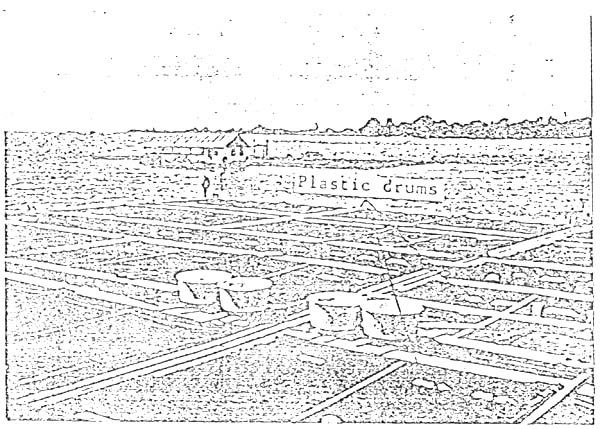
Figure III/7
Plastic drums (200 L each) used at floating
fish farm
Figure III/8
Trapezoidal concrete block used as anchor for
floating fish farm
Figure III/9
Position of concrete blocks used in floating fish farm
Figure III/10A
Preparation of a half oil drum for making a
concrete anchor block.
Figure III/10B
Preparation of anchor blocks
Figure III/11
Rope-float system for anchoring floating fish farm
Figure III/12
Eye solace used in anchor rope
Figure III/13
Metal parts used in construction of a floating
fish farm
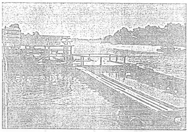
Figure III/14
Construction of central walkway and floating hut
(work in progress)
Figure III/15
Heavil fouled plastic drum after 3 months
immersion
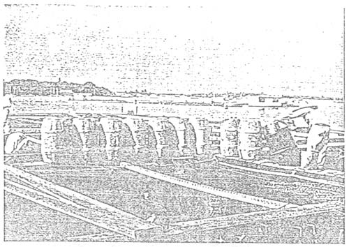
Figure III/16
Reconditioning of plastic drums (scraping, washing
and repainting)
Figure III/17
Releasing drum float from the raft unit by pushing
it out after untying.
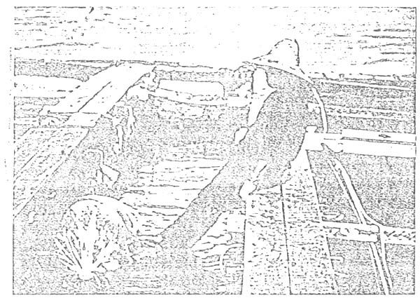
Figure III/18
Pushing drum float into position
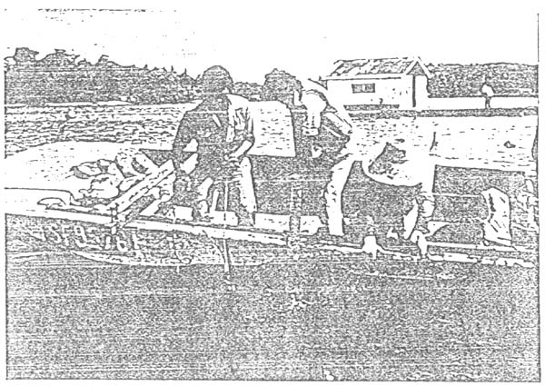
Figure III/19A
Maintenance of anchorage : Lifting
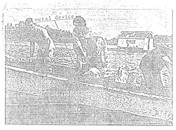
Figure III/19B
Maintenance of anchor rope : Cleaning
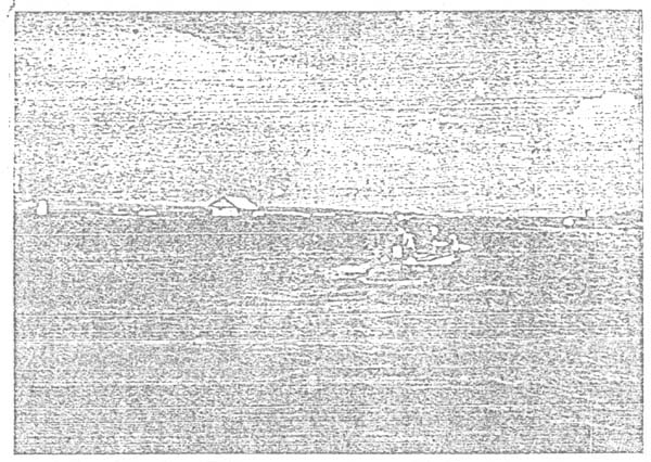
Figure III/19C
Maintenance of anchor rope : Reoositioning
cleaned anchorage
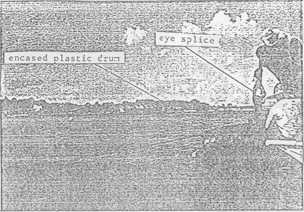
Figure III/20A
Changing of anchor float : Note eye splice of
anchor rope and the replaced plastic drum
encased om rope-network
Figure III/20B
Changing of anchor flcat : Lowaring of anchor rope to
to release anchor float and rope
![]()
![]()
![]()