(24) The functions of a laboratory scale experimental feed mill were discussed with FRI/FARS staff. The feed mill envisaged will have the capability to process raw materials and agricultural commodities and by-products into 8 different types of diets. This number of diets is deemed a necessary research capability, in order to provide appropriate diet formulae with desirable feeding characteristics for the many species of finfish and crustaceans to be reared under different aquaculture strategies in freshwater, brackishwater and marine water conditions.
(25) For specific applications the following formulations are foreseen (see Annex M):
(26) General functions of an experimental feed mill can be found in Annex M.
(27) Line operations of the experimental feed mill include several common pre-processing steps, and then a final feed manufacturing line. The various feed milling and manufacturing lines can be found in Annex N. These lines (after reprocessing of feedstuffs) are:
(28) A feed mill design was developed considering the capabilities needed for the various diets to be tested at FARS, BARS and MFRS. Pre-processing of raw materials, agricultural commodities, by-products of industry and unconventional materials available for diet formulation for larval feeds, for fry feeds, for supplemental feeds and for complete nutrient balanced feeds was incorporated into the design.
(29) The first step in feed mill operating is cleaning the materials from sand, dust, weeds and adulterated ingredients, whereafter they are ground to desired particle size for surge bin storage. A vibrating screen with blower feeds the cleaned material into the hammer mill, equiped with 1 mm, 2 mm, 3 mm or 4 mm screens. Following grinding, dry materials are stored until weighed into the mixer. After mixing to formulae, premixes from the twin shell blender are added, oils are incorporated and final mixing to homogeneous mass occurs. Material then flows to final processing units where various type diet particles are produced, then packaged and stored until fed.
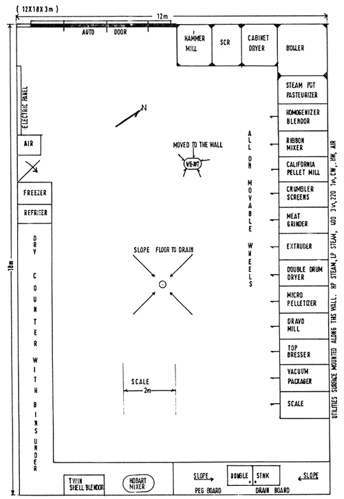
(30) Utility and space considerations resulted in the tentative schematic design found in Figure 1.
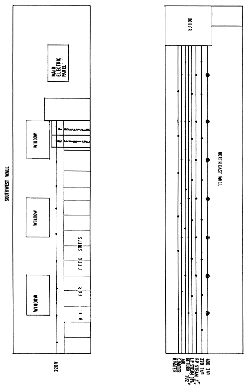
(31) Utilities necessary for complete operations include high pressure steam, low presure steam, steam return to boiler, 440 V (3 phase) and 220 V (2 phase) power, hot water, cold water and air lines. All lines should be surface mounted along the solid wall. Counter space is located under windows and includes a large double sink for cleaning the feed mill equipment. Storage bins for feed components are located under the working counters.
(32) Walls behind the movable feed processing units are epoxy-coated to allow wash down cleanings after feed operations. All floor surfaces are finished to allow movement of process-units on rollers into line position for convenient sequential processes. Floor is sloped to a central drain for wash down and post-process clean-up.
(33) A large ventilator fan is located in the top center of the solid wall to evacuate fumes and to control heat and humidity in the room.
(34) A large entrance doorway provides for delivery of feedstuffs in bulk and for transport of heavy equipment and finished feed to the storehouse. Small refrigerators and freezers are available for special materials and a large walk-in freezer must be located adjacent to the large doorway to hold perishable raw materials and finished semi-moist extruded frozen feed. Elevation of the floor to truck delivery height will allow easy off-loading of materials and loading of finished feed.
(35) The capacity of each line will be about one tonne per day except for the special flake feed and micro-pelletized larval feed lines which will be limited to several kilograms of production per day.
(36) The site for the experimental feed mill was discussed with staff and engineers on Station. It was agreed that the 12 × 18 meter building could be located west of the current feed storehouse. This site would be most convenient for movement of materials and storage of finished feed, since it is in the immediate area of the hatchery and with good access to the experimental ponds where feed testing would be performed. In addition, all feed processing would be in an area outside the main laboratory building and any noxious fumes would be dispursed away from the main buildings. The site concerned has available standby electric generator power and an excellent water supply.
(37) The building size would allow set up of at least two feed manufacturing lines at one time with sufficient space for movement around equipment in operation. A large drainage flume immediately adjacent to the west-side of the building would allow waste and floor wash down material to be flumed into the irrigation water channel for the BAU irrigated farm.
(38) In discussions with DANIDA it was indicated that they will consider designing and constructing the building and providing the utilities in their proposed Phase III of the Mymensingh project, which is under preparation. Correspondence with DANIDA regarding this further completion of the FARS facilities is underway.
(39) Equipment needed for the feed mill is identified on the schematic layout in Figure 1; elevations are presented in Figure 2. Price estimates of individual pieces of equipment can be found in Annex 0. Current prices and specifications for each item needed are collected in the USA and included in this report as Annex P.
(40) The list of equipment in Annex 0 is also based on the consideration that there is some equipment in Chandpur in the previous Fisheries Technology Laboratory. This equipment is out of use for a long time and could be transferred to FARS. This Chandpur-equipment is listed in Annex Q. The large Wiley mill equiped with 1 mm, 2 mm and 6 mm screens should be transferred and installed at FARS as soon as possible. It provides good feedstuffs grinding capability for the national feedstuffs survey. In addition, the large walk-in freezer at Chandpur should be relocated at FARS in one of the garage stalls adjacent to the standby power generator in order to provide freezer and cold storage space desperately needed today to hold the fish available for sale following current spawning programmes at FARS. This freezer will also be needed later as a back-up for the feed mill freezer and for surges in wet meat and other wet materials supply.
OUTLINE FOR EXPERIMENTAL FEED MILL (FIGURE-1)

PLACE WINDOWS OVER SINK AND DRY COUNTERS ONLY. LOCATION OF 10 TON FREEZER ADJACENT AUTO DOOR
ELEVATION OF FEED MILL (FIGURE - 2)
