![]()
![]()
![]()
by
Harry L. Cook, Somnuk Wechasitt,
Chuah Toh Thye and E. Selvam
| ABSTRACT |
| This paper describes the problem of poor water circulation in acid-sulphate brackishwater aquaculture ponds which results in stratification. An aeration system designed to create circulation of pond water and prevent stratification is described. The system is composed of two components; central divider in the pond and panel air-lift pumps. |
The Brackishwater Aquaculture Research Centre in Gelang Patah, Malaysia has ponds constructed of acid sulphate mangrove soil. The submerged soil in mangrove areas often contains large amounts of pyrite (Fe S2). When the soil is disturbed and made into dikes, exposure of the pyrite to air causes oxidation which makes the soil acidic. Rainwater falling on this soil also becomes acidic and as it runs off the dike into the pond it carries large amounts of dissolved iron into the pond. As it enters the pond the carbonate in the pond water neutralizes the acid, and as the pH rises the iron precipitates as insoluble Fe(OH)3.
If the amount of fish is great the pond water becomes stratified. Comparative values of pH, salinity, temperature and dissolved oxygen (DO) between surface and bottom layers show that stratification occurs frequently. Variations as great as 5° to 10°C, 1 to 3 pH units, 5 to 10 ppt salinity and 1 to 3 ppm DO have been observed. When rainfall is heavy during periods of neap tide the water exchange is restricted and the problem can become critical.
In one instance after a rainfall of 55 cm the following conditions were observed. In the surface layer salinity was 15 ppt, pH 3.75, and DO 8.0 ppm. At that pH the calculated value of alkalinity would be 0 and that of CO2 would be over 80 ppm. At the bottom, salinity was 20 ppt, pH 6.45 and DO 2.5 ppm. The critical factor is the low DO level of the bottom water. As the shrimp become stressed by the low levels of DO they swim to the surface, which is an unacceptable environment due to the low pH. In this case Penaeus monodon 7–10 cm long were actually observed jumping out of the water trying to escape and a mass mortality occurred.
In an effort to learn how tidal exchange of water affects the circulation and stratification in ponds a series of observations were made during intake of tidal water. Subsurface floats were used to monitor water flow. The floats were made from 20 × 13 cm plastic bags which were filled with water. A small stone was placed in the bag so that it would sink. The bag was then tied off with all air forced out. A 30 cm string connected the bag to an 8 × 3 × 1 cm wooden float. The wooden floats were wrapped with plastic of different colours in order to identify them. The water area of the pond used for this study was 35 × 85 m (about 0.3 ha). A sluice gate was located on one end near the corners.
The floats were released in front of the gate as water was let into the pond. When inflow started water depth varied from 50 to 68 cm and full depth was 100–105 cm. Water in the supply canal was at least 30 cm above water level in the pond so the flow rate was good. It took from 45 min to 1 h and 20 min to reach full pond level. These studies showed that only about 50 to 60 percent of the pond area was affected by the inflowing water (Figure 1a). The distal portion of the pond was not affected.
In an effort to improve circulation within the pond a fence was placed in the pond to direct water to the far end. This is essentially the same approach as tried by Sivalingam who constructed an earthen divider in the pond. The fence was made of plastic mosquito screen. After a week or so in the pond the screen material became covered with algae and made an effective barrier. Observation using the floats showed that the fence did direct flow to the far end of the pond (Fig. 1b), but in the short time involved the water did not really circulate around the pond.
Since problems were still encountered with stratification and low levels of DO in the ponds, it was decided to aerate mechanically. There have been several studies in recent years which have discussed the relative merits of different methods of aeration. Earlier researchers such as Rappaport, Sarig and Marek (1976) and Mitchell and Kirby (1976) favoured mechanical aerators over sparger type aerators, because of the high initial cost and maintenance problems with fine bubble diffusion systems. More recently, Parker (1981) reported that aeration/destratification was cost-effective in catfish ponds when twenty 3.8 cm air-lift pipes in a 0.16 ha pond were used. The recent research has shown that mixing is perhaps more important than oxygenation, and Busch (1980) designed a slow moving paddlewheel to provide aeration through pond circulation. The benefits of water circulation were summed up by Boyd (1982), who stated: “Mixing prevents thermal stratification, and oxygen released in surface water by phytoplankton is dispersed throughout the entire pond. Because deeper water of a mixed pond contains oxygen, the entire pond volume may be inhabited by fish and other animals. Mixing equalizes concentrations of chemical substances, and agitation of surface waters favours diffusion to the atmosphere of carbon dioxide and ammonia. Oxygen in deeper waters helps prevent the accumulation of organic matter on the bottom of the pond.”
The aeration and circulation system developed at this station consists of two components: a central divider in the pond and air-lift pumps. The idea of a central divider was adopted from a system observed by Cook at an eel farm in northern Italy. The visit to the Società Allevamento Primo Stadio Anguille S.p.A. (SAPSA) farm was arranged by Dr G. Ravagnan as part of an FAO mission studying development of coastal aquaculture in the Mediterranean Region.
At Gelang Patah, earthen ponds with a water surface area of 85 × 23 m (about 0.2 ha) were used for the studies with aeration. A divider made of asbestos concrete (a/c) roofing sheets and mangrove posts was built down the middle of the pond. A space about 10 m was left at each end, between the fence and the pond dikes. The object is to move the water in the pond, causing it to circulate around the divider like a raceway. To move the water a series of 1 m long panel air-lift pumps (Figure 2) were used. The air-lift panels were made at the station from locally available materials. The side walls were initially made of asbestos concrete ceiling sheets, but this material was heavy and cracked easily. Later, aluminium sheeting used for making outdoor advertisement displays was used. The important factors to be considered when making and using the air-lift panels are:
Internal dividers. The internal dividers make the air-lift essentially a series of rectangular pipes. If they are not included the water and air surge to one side causing uneven flow. Movement of water through the air-lift creates a vacuum at the bottom portion of the air-lift and if supports are not provided the two sides would come together.
Placement of the sparge pipe. Trial and error showed that the system performs best when the sparge pipe is 65 cm below the surface of the pond water. If the sparge pipe is deeper, greater air pressure is required. There is a relationship between airflow and waterflow in which there is a decreasing benefit with depth below 65 cm. An important factor is the cost of the air. Regenerative blowers are most efficient at lower pressures. If the sparge pipe is set shallower than 65 cm the water flow decreases, because the height of the air-lift column is too short to be effective.
The panel wall on the intake side of the air-lift must extend above the water line.
The panel wall on the outlet side of the air-lift should not be too close to the surface. Again by experiment, a space of 15 cm was shown to be best.
Size of hole in the sparger. Several types of sparger were tried and it was found that a fairly large size bubble works best. Very small bubbles do not provide as much waterflow and the holes in the spargers tend to clog. Micro-Por 1.5 cm tubing1 was used. These spargers require a great deal of pressure and make a bubble that is very small. Larger holes were punched in the tubing with a number 12 sewing needle. A single line of holes is made, with the holes spaced about 2 mm apart. The porous plastic material makes an even hole which retains its shape.
The air distribution system which carries air from the blower to the air-lift panels is important. Line losses increase rapidly with increase in flow velocity, and consequently air line sizes should be kept as large as practical (Castro and Zielinski, 1980). Experimental work was started with a Rotron model SL 2R air blower. This is a small blower with a maximum flow rate of only 95 CFM and a flow at maximum pressure of 40 CFM at 6000 RPM. Following instructions of the sales representative it was operated at only 4 500 RPM. The blower was operated by a 4 HP petrol engine. Initially it was attempted to operate three 122 cm wide air-lift panels at a single location in one pond. A line of 2.5 cm diameter plastic tubing 12 m long was used to carry air from the blower to the air-lifts. The flow of air was insufficient. Later, hoping to improve results, the same blower was connected to a 5 cm diameter PVC pipe which extended for 48 m between three ponds. Air was carried from the pipe out to the air-lifts in the ponds with 14 m long pieces of 4.6 cm diameter plastic tubing. It thus proved possible to supply sufficient air to operate six air-lift panels in three ponds.
It is necessary to have an exhaust value to waste excess air, and in larger systems a pressure gauge is needed. In operation the exhaust value is opened or closed so that an operating pressure of 115 cm of water is obtained.
Placement of the air-lifts in the pond is important. In the 0.2 ha ponds the airlifts are placed at one end of the centre divider as shown in Figure 1c. Three units were used initially. After letting the air-lifts operate for one hour, floats were released in front of the air-lifts. The floats followed the pattern shown in Figure 1. Speed was about 4 m/min. The speed of 4 m/min was thought to be unnecessarily fast, so in subsequent trials only two air-lifts panels were used.
To test the effectiveness of the air-lifts in maintaining favourable pond conditions, an experiment was undertaken in the 0.2 ha pond. Aeration was intended to operate from 24.00 h to 07.00 or 08.00 h; however, problems with the petrol engine and maintaining an adequate level of water in the pond during periods of neap tide caused the schedule to be broken from time to time. (As described later the air-lift pump was modified so that it could operate at all water levels during the culture periods.) The pond was stocked with 6 800 shrimp (P. monodon) with an average weight of 7.7 g. They were fed a pellet made at this station. When harvested after 70 days the shrimp had grown to only 15 g. The rate of survival was 64% and yield was 69 kg or 345 kg/ha. These results are not bad for this station's acid sulphate ponds, especially as it rained heavily during the experiment. Daily rainfall exceeding 5 cm occurred on three occasions and total rainfall during the period was 47.2 cm. The mass mortality of P. monodon described earlier occurred during this time when the air-lifts were not operating.
1 Registered trade mark Micro-Port Inc., Wichita Kansas, USA
Measurement of temperature, salinity, pH and DO were made on several occasions over a 1-month period. The sampling was conducted at 08.30 h on days when the air-lifts had been run from about 24.00 to 07.00 h. Samples were taken at four points around the pond: one at each end and one along each side. The sampling showed that variation between different places in the pond was usually greater than variation between top and bottom at any one place. There was no stratification. The lowest value of DO recorded was 5.8 ppm. The favourable conditions in the pond were reflected in the bottom. At the start of aeration the anaerobic zone extended almost to the surface. After a month, the top 2 cm was no longer black, it had become brown. Filamentous green algae started growing on the bottom.
As pointed out by Colt and Tchobanoglous (1981) energy costs represent a major item in the operating budget and increase in the cost of energy will make this factor even more important in the future. The system described above is energy efficient. A one-half horsepower regenerative air blower can supply sufficient aeration for three 0.2 ha ponds. To operate a one-half horsepower motor for 8 h a night would require only 3 kW of electricity. Another major advantage of using the air-lift in salt water ponds is that there are no moving parts in contact with the seawater. In contrast to other diffused air systems there is no need for a complex system of feeder lines. No problems were experienced with clogging of the sparge tube.
In tidal ponds the major problem experienced has been in maintaining the proper depth of water in the ponds for efficient operation of the air-lifts. During times of neap tides it was not possible to take in enough water to maintain water depth at 1 m. When water depth is insufficient the air-lifts do not pump enough water to cause water to start circulating around the pond. Only a small area near the air-lifts benefits.
The air-lift panel was modified so that it floated (Figure 3). Floats were attached to both sides by attaching a piece of wood across the top of the air-lift which extended far enough past the sides for the floats to be attached. Blocks of wood (5 × 7.5 cm) were attached to each and near the bottom. To serve as a guide to keep the air-lift perpendicular, wood posts were placed on each side of the air-lift so that the float support and wood block were held loosely between them. The air-lift itself was shortened to 70 cm high. A piece of thick rubber sheet (2 ply 3 mm thick) 50 cm long was attached to the bottom. This rubber material rests on the bottom and sides, keeping contact with the bottom as the air-lift moves up and down. The rubber must maintain contact with the bottom to prevent water from entering from the discharge side so that a one directional flow pattern is established. The air-lift panel performed well and continued to operate efficiently as the level of water in the pond fluctuated.
REFERENCES
Boyd, C.E. 1982 New aeration tests may provide better basis for comparison. Aquaculture Magazine, 8(4): 28–31
Busch, C.D. 1980 Water circulation for pond aeration and energy conservation. Proceedings World Mariculture Society, 11:93–101
Castro, W.E. and P.B. Zielinski. 1980 Pumping characteristics of small air lift pumps. Proceedings World Mariculture Society, 11:163–74
Colt, J.E. and G. Tchobanoglous. 1981 Design of aeration systems for Aquaculture. In Proc. Bio-Engineering Symposium for Fish Culture (FCS Publ. 1), edited by J.E. Lochie and E. Kinney. Bethesda, Maryland, Fish Culture Section of the American Fisheries Society, 138–48
Mitchell, R.E. and A.M. Kirby, Jr. 1976 Performance characteristics of pond aeration devices. Proceedings World Mariculture Society 7:561–81
Parker, N.C. 1981 Performance of four aeration devices in channel catfish ponds. 1981 Catfish Farmers of America Research Workshop, Las Vegas, Nevada, 8–9
Rappaport, A., S. Sarig and M. Marek. 1976 Results of tests of various aeration systems on the oxygen regime in the Genosar experimental ponds and growth of fish there in 1975. Bamigdeh, 28(3): 35–49
Sivalingam, S. Improved designs for double and single gate tidal aquaculture ponds (MS.)
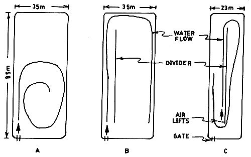
FIGURE 1. WATER CIRCULATION PATTERNS IN PONDS:
A.0.3 HA POND: B.0.3HA POND WITH DIVIDER;
C. 0.2 HA POND WITH DIVIDER AND AIR-LIFT.
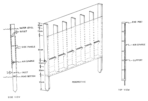
FIGURE 2. AIR-LIFT PANEL
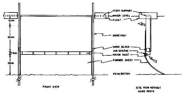
FIGURE 3. FLOATING AIR-LIFT PANEL
![]()
![]()
![]()