Facilities for growing indicator plants
Indexing on vitis indicators
Use
of herbaceous hosts
Facilities for growing indicator plants
C.N. Roistacher
THE GREENHOUSE OR PLANT LABORATORY
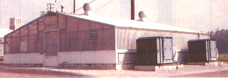
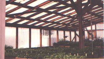
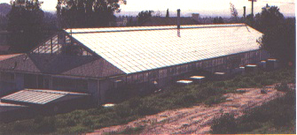
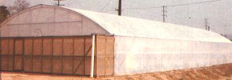
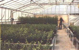
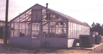
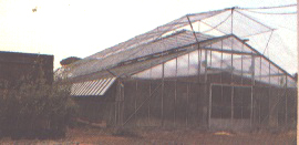
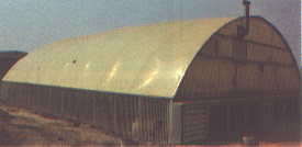
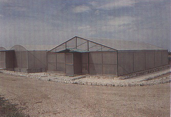
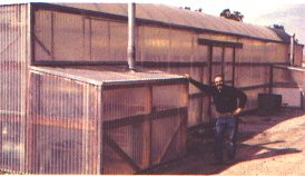
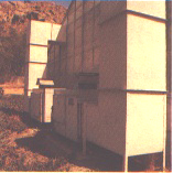
A greenhouse, or a controlled-environment structure, is necessary for the production of index plants and for indexing (chip-budding prior to transplanting in the field and green grafting). This structure need not be expensive or elaborate. It should provide light, heat and cooling and be sufficiently well constructed to prevent insect intrusion. An entrance with two doors and a darkened vestibule between is desirable as a preventive measure against insect invasion. The greenhouse covering can be of glass or plastic. Excellent plants can be grown in a simply designed and inexpensive wooden structure covered with heavy fibreglass and containing a good system for heating and cooling. Modern structures are now made with extruded aluminium framing.
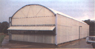
A sketch of three general greenhouse structures is shown in Figure 145. A number of greenhouse and screenhouse structures in use worldwide are shown in Figures 146 to 156. In areas where hailstorms are frequent, glass coverings should be avoided, but if used they should be protected with wire mesh. Corrugated fibreglass rather than glass is recommended where hail is a problem, and in many respects is preferable since it may be less expensive, does not break and may be easier to construct and maintain.
The size of the greenhouse will depend upon the amount of indexing and research to be carried out. It may be convenient to have two compartments: a cool room for indexing graft transmissible pathogens which are best expressed in plants grown under relatively cool temperatures (22 to 24°C); and a warm room (up to 34 to 35°C) primarily used for preconditioning vines prior to thermotherapy.
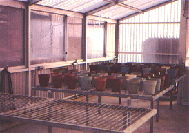
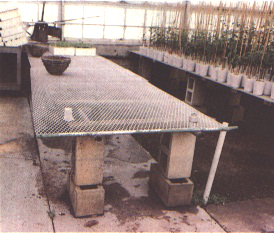
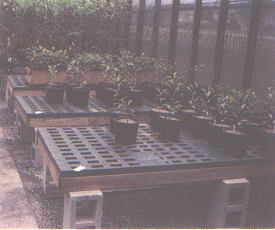
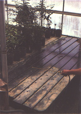
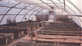
Benches
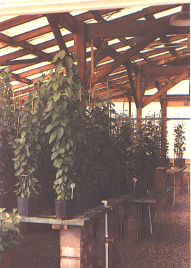
Benches can be made of wood. concrete, wire mesh, plastic or any satisfactory containersupporting system (Figures 157 to 163). If wooden benches are used, it is advisable to paint or spray them with 2 percent copper naphthenate solution (Roistacher and Baker, 1954), which acts as both a wood preservative and a disinfectant (Figure 164). Wood benches can be placed on concrete blocks or on a metal frame or other foundation at a height of not less than 80 cm from the ground.
Flooring
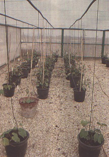
Flooring can be of concrete with provisions for drainage. However, gravel flooring with a concrete walk is recommended. Gravel of 1 to 2 cm diameter should be spread over the ground about 8 to 10 cm thick. This provides good drainage and aids in maintaining sanitation. The greenhouses should be constructed on a welldrained soil base. If this is not possible, supplementary underfloor drainage tiling should be provided prior to construction.
Containers
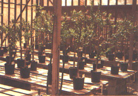
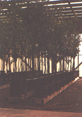
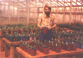
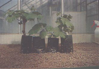
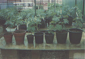
Grapevines may be grown in rigid plastic or clay containers of any suitable size. Plastic disposable containers (Figure 165) are useful for transplanting rooted indicators immediately after chip-bud grafting, prior to transfer to the field. For prolonged maintenance of vines under greenhouse or screenhouse conditions, large (25 to 35 cm in diameter and 25 to 35 cm deep) cylindrical or tapered plastic or clay pots (Figure 166) can be used. Drawbacks of clay pots are that they accumulate salts, are heavier, are subject to breakage and must be soaked in water and washed after each use.
Temperature control
It is important to have a recording thermograph in each room. These should be periodically calibrated against two thermometers for accuracy. At the end of each week, when charts are changed, the maximum and minimum temperatures should be recorded in a special book. This provides a record for research and is also a means of noting any abnormal changes, which give warning of heating or cooling unit failure or breakdown.
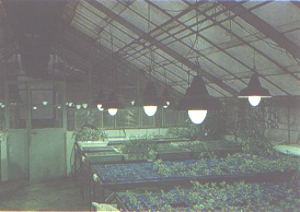
Supplemental lighting
During the grapevine vegetating season (April to October) no supplemental lighting is required. It is necessary, however, for growing herbaceous indicators in winter months. In the temperate zone (roughly from 30 to 45° N latitude) the addition of 4 to 5 hours of 2 000 to 2 500 lux at the plant level from October to April is useful. Light sources may be fluorescent tubes or incandescent bulbs (e.g. Philips HLRG 400 W) (Figure 167).
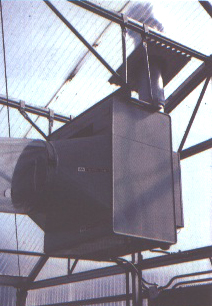
Heating
Heating can be provided by gas heaters with fans, by steam heating using radiators or by steam pipes placed along the sides of the structure. Heat may also be distributed from gas heaters using supplementary fans blowing the heat through perforated plastic tubes. Most gas heaters are placed inside the structure. However, ethylene released by faulty heaters can be very damaging to plants. If feasible, gas heaters should be placed outside (Figures 168 and 169) rather than inside (Figure 170) the structure, and the warm air circulated by a fen inside the greenhouse, preferably by forcing the air through large-diameter perforated plastic tubes (Figures 170 to 172). The construction of a greenhouse or screenhouse is best carried out through local builders, with design and facilities suggested by those in charge of indexing.
Cooling
There are three general methods for cooling a greenhouse: introducing air from the outside when the temperature is cooler than that inside the structure; use of evaporative coolers if the relative humidity is low enough to make such cooling effective; and refrigeration. There may be other innovative methods, such as the doublelayered plastic bubble which acts both as an insulator and as a sandwich through which cool (or warm) air can be forced. Combinations of any of these methods may be used for economy and efficiency depending upon local conditions.
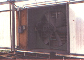
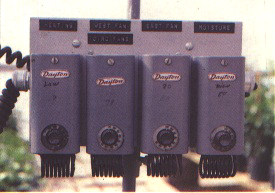
Air cooling. The simplest and most economical means of cooling a greenhouse is by bringing in outside air to replace the warm air within. This is best accomplished by using fans (Figure 173) and thermostatic control (Figure 174). When the temperature rises the thermostat is activated, the fans turn on and the cooler air is drawn through the greenhouse. A greenhouse designed to utilize the cooling ability of the outside air will save much expensive energy and wear on cooling equipment. Air brought in from outside must be screened or filtered to prevent introduction of insects. Figure 175 shows an air filtering device containing both 32-mesh plastic screen and glass wool filters. This system also has charcoal trays to filter out air pollutants.
The thermostatic controls shown in Figure 174 are designed to control both heating and cooling. As the temperature rises inside the greenhouse the thermostat will activate the fan (Figure 173), thus bringing outside air into and through the house and forcing the warm air outside. When the temperature increases further the thermostat switches on the water pump, which sends water to the cooling cell to begin evaporation cooling (see Figure 178).
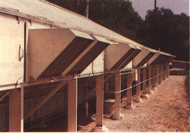
Another way of using outside air to cool a greenhouse is to have vents at the peak of the roof. Vents may be activated mechanically, by hand or by a thermostatically controlled motor. When the vents are opened, they permit the warmed inside air to rise and bring in the cooler outside air through filtered vents at the lower sides of the structure. Many problems are associated with this method of air cooling, and though it is present in many older installations, it is generally not recommended for a plant laboratory greenhouse.
Evaporator coolers. Evaporator coolers are recommended for most greenhouses when humidity during summer months is low. An engineering study should be carried out to calculate the cooling ability of evaporator coolers where humidity is moderate or high during the warm months. Evaporator coolers may prove uneconomical and unsound if the relative humidity is too high. However, in some areas evaporator coolers can be combined with refrigeration for efficient cooling.
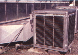
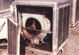
Equipment and methods for cooling by evaporation are shown in Figures 176 to 179. Figure 176 shows a standard commercial evaporator cooler available in most countries where humidity is low and where homes and buildings are cooled by this means. Figure 177 shows the inside of this cooler with the panel removed to expose the squirrel-cage fan, water reservoir at the bottom, water pump, water dripping down from the outlet at the top and pads made of wood fibre or glass wool housed inside the panel door. Such units should be carefully serviced each year by cleaning, painting and changing the cooling pads. A standby cooler should be available for emergency replacement, as well as spare water pumps, fan belts and drive motor.
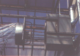
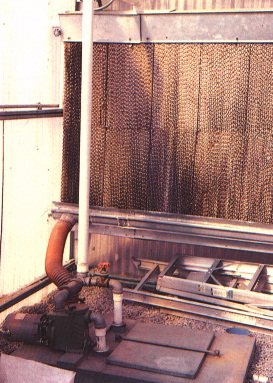
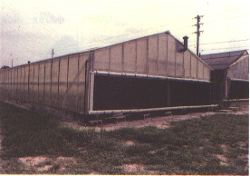
A more efficient apparatus for cooling is shown in Figures 178 and 179. Figure 178 shows cooling cells consisting of rectangular units of specially treated cardboard placed together to form a solid block. Water is pumped from a reservoir tank shown in the lower left of Figure 178 to a trough above the cell. The water then drips down by gravity over the cardboard cells. The outside air is forced through the moistened cells by the diminished pressure induced by the fans located at the opposite end of the greenhouse (Figure 173). The operation of the fans and water pump is controlled by thermostat. Figure 179 illustrates a greenhouse at Lake Alfred, Florida with this cooling system but without an insect filter screen. The cooling cells occupy the full length of the outside wall of the greenhouse.
Refrigeration. Refrigeration can be used to supplement evaporator coolers where the relative humidity is too high during the warmer months, where extra cooling capacity is needed as a supplement for the plants in a cool indexing room or for cooling small individual rooms. Small plastic chambers can be built inside a large greenhouse to give areas of controlled cooling using refrigeration. Figure 180 shows refrigeration units used to cool a grape-indexing facility in South Africa, where electrical energy is relatively inexpensive. Refrigeration is recommended for smaller greenhouses for those compartments to be held at cooler temperatures. These units should be designed to be easily removable for and replacement, and a spare unit should be held in reserve to replace any that may need repair.
SOIL MIX FOR PLANT GROWTH
Plants for indexing, regardless of whether they are herbaceous or woody. should be of the highest quality. Therefore, the soil mixture with its balanced supply of micro- and macronutrients is of prime importance. The University of California (UC) system for producing healthy container-grown plants was developed by Baker and colleagues (Baker, 1957), based on the John Innes system of soil mixes developed in England. The system was later modified (Nauer, Roistacher and Labanauskas, 1967, 1968) for growing citrus by the addition of micronutrients to the artificial mixture. This mixture is also suitable for growing grapevines.
Ingredients
The basic soil mixture consists of 50 percent Canadian peat moss and 50 percent fine sand, with macro- and micronutrients added to the mix (Figure 181). Although Canadian peat moss is recommended as the prime ingredient because of its superior nutrient retention and chelating ability, other peats from Europe (e.g. Finland, Poland, Germany, former USSR) can be used after appropriate testing. Alternative ingredients such as wood shavings complemented with extra nitrogen, sphagnum mosses, perlite or vermiculite can be tried whenever necessary.
It is recommended that a fine sand or silt, with a particle size ranging from 0.05 to 0.5 mm, be used. Beach sand should be avoided. Fine sand can be found in rivers, in wind-blown deposits or as the fine silt separated out as waste material from a sand and gravel processing pit. A quick and simple test for determining the presence of clay in a sand source is to shake a sample of the
test soil in a jar with water. If the sand settles fairly rapidly and the water remains relatively clear, it is satisfactory. If clay is present, the water will have a muddy appearance, and that source of sand should preferably not be used. The sand should be inert and preferably siliceous. Calcareous and limestone sands should be avoided since they may affect the pH. If a high-grade silicate sand is not available, consideration should be given to a substitute mix of peat, vermiculite and perlite in a ratio of 2:1:1 or 1:1:1. The objective is to obtain an artificial mixture that is consistently reproducible, will absorb and release macro- and micronutrients and will maintain pH of the drainage water at 5.5 to 6.5.
The ingredients can be mixed together with a shovel on a flat concrete surface.. However, a small or medium-sized electric or gasolinepowered concrete mixer is the preferred mixing device. In this case the procedure is as follows:
Fertilization
The initial mix contains both macro- and micronutrients added during mixing. The micronutrients are tied up in the peat moss. The peat, which acts as a chelating agent, releases sufficient small amounts of micronutrients to the plants for up to one to two years (Nauer, Roistacher and Labanauskas. 1967; 1968).
Liquid fertilizer is applied with each watering using a proportioning device. There are a number of such devices, which inject fertilizers in proportion to the water used. An effective, simple and very inexpensive device is a Venturitype siphon. Before use the siphon should be calibrated, for many such devices vary considerably from the advertised ratio of concentrate to water as printed in the instructions. To calibrate the siphon, put a measured amount of water (500 or 1 000 ml) in a graduated cylinder, then place the suction end of the siphon into the cylinder and measure the final amount of water exiting from the hose. Allow the water to fill a container until the 500 or 1 000 ml of measured liquid is siphoned up. Then measure the water in the container and convert the results to a ratio.
Another device that injects a given quantity of liquid fertilizer into the water system at a uniform rate in direct proportion to the water flow is the Smith Measuremix proportioner. This is a highly reliable, precision instrument. However, it should be calibrated in the same manner as the Venturi siphon.
A liquid fertilizer formula based on that given by Nauer, Roistacher and Labanauskas (1968) is: 9 parts ammonium nitrate + 3.75 parts calcium nitrate + 2.75 parts potassium nitrate or potassium chloride. This fertilizer should be we 11 mixed and applied at the rate of 67.5 g of mixture to 100 litres of water.
With the UC system of soil mix, the soil should be fertilized directly after mixing and before and immediately after planting since the basic mix contains no nitrogen or potassium. As a general practice, potted plants in a UC system need to be watered periodically with enough volume to flush out any accumulated salts, thereby preventing salinity buildup. It is important that the soil not be filled to the top of the container; a space of 2 to 3 cm should be left between the top of the container and the soil level. This will allow a sufficient volume of water to flush the soil in the container adequately.
REFERENCES
Baker, K.F., ed. 1957. The UC system for producing healthy container-grown plants. Calif. Agric. Exp. Sta. Extension Service Manual 23. Repr. 1985. Chipping Norton, Australia, Surrey Beatty and Sons.
Nauer, E.M., Roistacher, C.N. & Labanauskas, C.K. 1967. Effect of mix composition, fertilization and pH on citrus growth in UC-type potting mixtures under greenhouse conditions. Hilgardia, 38: 557-567.
Nauer, E.M., Roistacher, C.N. & Labanauskas, C.K. 1968. Growing citrus in modified UC potting mixtures. Calif: Citrogr., 53: 456, 458, 460-461.
FIGURE 158 Another view of wood and concrete block benches at Riverside, California
FIGURE 160 Benches made of concrete at Campinas, Brazil
FIGURE 161 Steel and wire mesh benches, Mildura, Australia. Note the concrete floor
FIGURE 162 A steel mesh bench on concrete blocks at the USDA greenhouse, Orlando, Florida
FIGURE 165 Soft plastic containers suitable for growing rooted grapevine cuttings
FIGURE 166 Various types of plastic and clay pots for growing grapevines
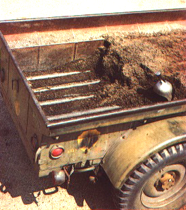
FIGURE 183 Flats and pots can be steamed directly in the trailer
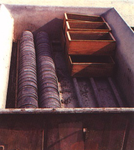
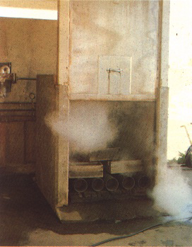
FIGURE 184 A fixed steam chamber used to steam containers