![]()
![]()
![]()
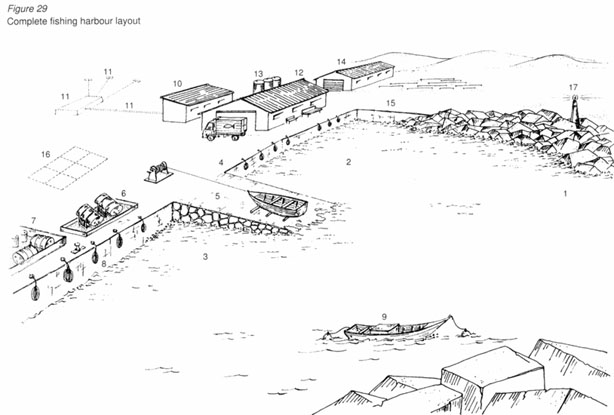
A good coastal fishing shelter normally consists of:
A breakwater to protect the moored fishing vessels in rough weather. A quay along which to moor the boats when unloading the catch. A slipway where the fishing vessels can be scrubbed, painted and serviced. Various shore facilities.
Occasionally there will also be areas of land reclaimed from the sea to provide space for the activities associated with fishing. In some cases, such as at the mouth of a river or where there is an open beach landing, the breakwater is not needed.
These are typical fishing harbour installations (the numbers in brackets refer to the numbers on Figure 29):
rubble breakwater, if necessary (1); fish-handling basin for offloading (2); boat-servicing basin for maintenance (3); quay wall with a minimum depth of 2 m (4); slipway with a simple winch (5); artisanal refuelling point (6); waste oil and slops disposal/separation facility (7); used car tyres recycled as fenders (8); tie-up area for boats waiting for spare parts(9); toilets and washrooms (10); landing/village sewage disposal (11); fish hall for sorting, packing, selling and icing fish, including ice store or small ice-plant (12); elevated fresh-water supply tanks (13); fishermen's net store, engine spares, hawker stalls and recreation areas (14); flat area set aside for net repair (15); parking area set aside for fishmongers if landing is close to a big market (16); aids to navigation (17).
The purpose of a breakwater is to establish an area of calm
sea where boats can be moored safely during rough weather. It is
important for the local community that such a breakwater can
withstand the pounding of waves that are normal for the area
(that is not counting freak or rare storms). If a breakwater
cannot stand up to normal conditions the fishing fleet may be
badly damaged. To avoid this happening, particular care should be
taken when a breakwater is being built with little or no direct
help from the public works department. On rocky coastlines,
breakwaters in depths exceeding 3 m should not be attempted
without technical assistance. This is because waves in deeper
water are difficult to predict. On sandy coastlines expert advice
should always be sought, irrespective of how deep the water
is.
The typical breakwater consists of a mound of coarse stone,
known as a core, covered or protected by blankets or layers of
heavier stones (Figure 30).
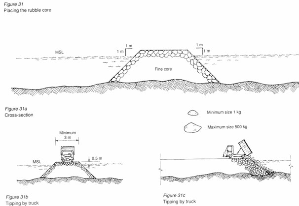
The core typically consists of
coarse quarry waste, without fine particles of dust and sand.
This is dumped in a heap into the sea by a dump truck. To make
dumping by truck easier, the core should ideally be 4 - 5 m wide
at the top and approximately 0.5 m above mean sea level or, when
there is a large tidal range, above high water spring level
(Figures 31 a to 31 c). The top of the core should be kept level
and uniform by a bulldozer. This allows the dump trucks to travel
the entire length of the breakwater while it is being
constructed. When tipped into the water, the core rubble comes to
rest at a slope of approximately 1 on l (sometimes written 1/1).
This is a slope that drops down 1 m in height for every 1 m it
goes forward. The rubble in the core is very light, so
breakwaters should be built during calm seasons only.
Chapter 4 describes in detail the type of rock that is suitable
for a rubble breakwater.
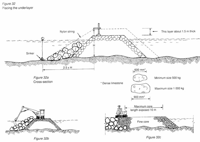
The first underlayer of stone
(Figures 32a to 32c), which protects the core rubble from being
washed away, usually consists of single pieces of stone whose
weight varies from 500 kg to 1 tonne (1 000 kg).
These stones are usually laid in a minimum of two layers at a
slope that is shallower than that of the core; 2.5/1 on the outer
slope and 1.5/1 on the inner slope. A slope of 2.5/1 means that
the height of the slope drops 1 m for every 2.5 m it goes
forward. The first layer of stone can be placed by a hydraulic
excavator (Figure 32b and 32c). A normal crane may also be used
if space for the outrigger pads is available. Rubber tyred cranes
should never be used on an uneven core without the pads in the
extended position.
The excavator should place the heavier stone underlayer as
quickly as possible so that the core rubble is not exposed to
wave action. If a storm strikes the site when too much core is
exposed, there is a grave danger of the core being washed away
and spread all over the intended port area.
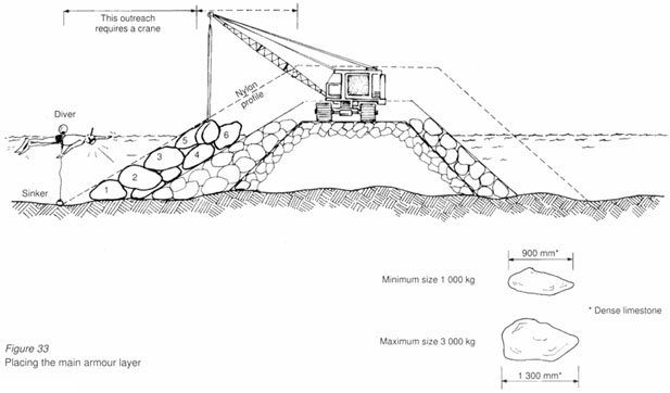
Figure 32a shows the set up for a given stone profile. In this case the slope is 2.5/1 and the distance, H, is the height of the top of the underlayer above the sea bed. A wooden pole should be placed on top of the underlying core and cemented into place with mortar. At a distance equal to 2.5 x H, a heavy stone sinker with a marker buoy should be placed on the sea bed. A brightly coloured nylon string should then be strung from the sinker to the required height (H) on the pole. This procedure should be repeated every 5 m to help the crane or excavator operator to place the top most layer at the correct level. A swimmer wearing goggles could ensure that each separate rock is placed within the profile outlined by the nylon string.
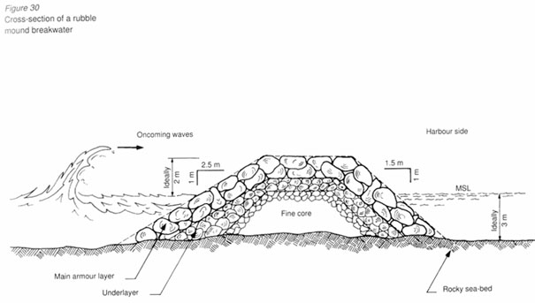
The main armour layer, as its name implies, is the primary defence of the breakwater against wave attack. Any defects in the quality of the rock (see Chapter 4), in its grading (such as using rocks that are too small) or its placing (on a slope that is uneven or too steep) will seriously put the whole breakwater at risk. Hence great care must be taken when choosing and placing the stone for the main armour.
Figure 33 shows stone for the main armour being placed by a crawler crane or tracked crane. Such a crane is by far the best equipment for placing large stones. The large stones should be lifted singly using a sling or grab. They should be placed in the water with the aid of a diver or of the crew of a boat equipped with a glass-ended tube. The armour layer should be placed stone by stone in a sequence that ensures interlocking. In Figure 33, for example, stone 2 is held in place between stones 1 and 3. Stone 4 is jammed between stones 3 and 5. This ensures that waves cannot pull one stone out, causing the upper stones to topple down the slope, breach the armour layer and expose the smaller rubble underneath.
To ensure that stones are properly placed, the swimmer or boat crew should direct the crane operator each time a stone is placed until the armour layer breaks through the surface of the water. As with the underlayer, two layers of armour stones are required to complete the main armour layer. Slope profiles should be set up at regular 5-m intervals using the same procedure as shown in Figure 32.
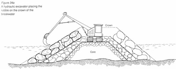
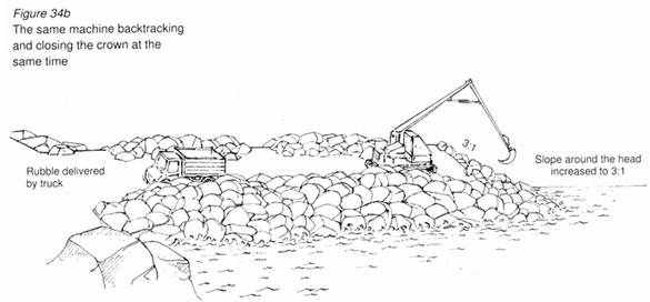
Figures 34a and 34b show how the nearly complete breakwater is
closed off layer by layer.
It shows the excavator backtracking to the root of the breakwater
and closing the top layers (or crown) as it does so.
The end, or head, of the breakwater is the most delicate part and requires extra care. The outer slope of 2.5/1 should be increased to 3/1 to improve stability.
Other types of breakwater. The type of breakwater just described is known as a rubble breakwater because it is made of rubble placed in a special manner. This type of breakwater adapts itself very well to most conditions, especially to varying sea bed depths; it can also sustain some damage from storms without completely breaking up.
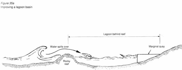
A rubble breakwater, however, is not always suitable. When a
rocky reef (not coral) already exists (Figure 35a), the ideal
solution would be to raise the level high enough to prevent the
breaking waves from spilling over the reef and on to the boats
moored behind it. As mentioned earlier, an anchored solid
breakwater should be constructed on the rocky outcrop. On the
other hand, if the reef consists of living coral, the breakwater
should be built inshore, if there is space for it, away from the
coral.
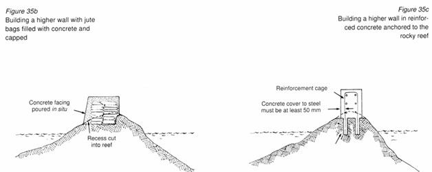
Figure 35b shows a recess cut into the reef and a solid
wall built from jute bags filled with concrete and placed in
position. When the concrete has set, after about 24 hours, an in situ capping should be poured all round the bags to form a smooth
finished wall. Alternatively, a solid reinforced concrete wall
should be built as shown in Figure 35c. In this case it is
assumed that a compressor and an air-drill are available on-site
for drilling anchor holes into the reef at, say 0.5-m intervals.
The reinforcement should then be cast into the drilled holes
using a very dry mortar mix.
Within a harbour, a quay generally lies parallel to the shoreline and boats are moored along the sea-side only. A jetty generally sticks out into the harbour waters and allows boats to be moored on either side. In protected waters a stand alone jetty may be all that is needed to make a satisfactory landing facility.
Quays. Quays can be either of solid
construction or built on piles. A solid quay, suitable for areas
where the sea-bed is rocky or sandy, is shown in Figure 36.
A piled quay (Figure 40) is more suitable in areas where the
sea-bed is very soft, such as on riverbanks or in mangrove
areas.
In areas where there are large tidal variations, the usual approach is to have a floating landing (Figures 44 to 46). A floating landing is also suitable on lakes, where water levels may vary from year to year by several metres. Before embarking on a project, a careful study should be made of the type of plant available as this will influence the final cost of the structure. In Chapter 4 there is a description of the type and quality of materials that should be used for construction works in sea water. Chapter 6 gives a general description of the types of fittings used and their anchorage requirements.
The solid quay in Figure 36 has been built from concrete blocks laid, by crane, on a screeded bed of stone chippings or aggregate. The concrete blocks are cast on the ground. After 28 days (which is the standard curing period), they were lifted and placed in the water in a line to form the quay wall. Each vertical pillar of concrete blocks should not touch neighbouring pillars so that it is free to settle independently into the screeded stone bed.
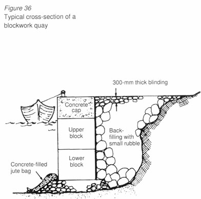
To prevent the propellers of fishing vessels from scouring the screeded stone bed, concrete-filled jute bags should be placed at the base of the quay to cover the stone bed for the whole length of the quay wall. A diver is usually employed to carry out this operation. The pillars of blocks should break the water surface approximately 500 mm above mean sea level, where a concrete capping block is then cast to cover the tops of five pillars, joining them together. The capping block should contain all the holes and recesses for the quay fittings, such as fenders, bollards and mooring rings.
The area behind the quay wall should then be filled in with small rubble. No dust, silt, clay or mud should be used because this would leak out from the gaps between the block pillars and lead to settlement of the paving.
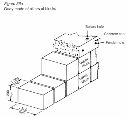
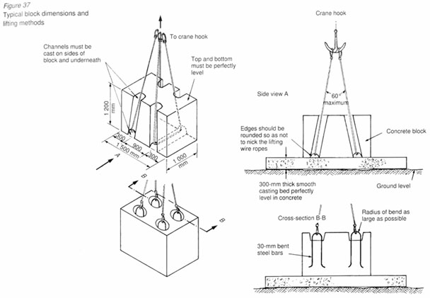
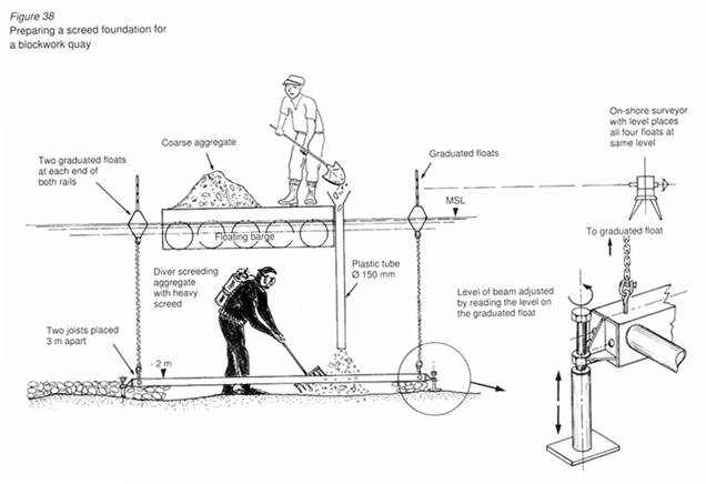
Figure 39 shows the cross-section of a solid quay which did
not require the services of a crane during its constuction.
Instead of using uniform blocks of concrete, jute bags were
filled with wet concrete and placed underwater by a diver. The
screeded stone bed is not absolutely necessary in this case, but
a layer of coarse aggregate is recommended. This increases the
stability of the foundation layer against scour by boat
propellers. Unlike the concrete block quay wall, this type of
quay does not have to be screeded perfectly level. Obstacles,
such as an uneven sea-bed or large boulders, can be included in
the foundation, but if possible they should be removed or the
quay wall diverted away from them.
The jute bags, once filled with concrete and stitched shut, should be placed in the pattern shown in Figure 39 to ensure a solid construction. Care should be taken not to overfill the bags; when laid flat and squeezed lightly, they should present a horizontal flat side on which to place the next layer of bags.
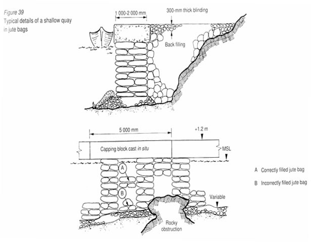
The quay wall should then be completed with a concrete capping block as described for the concrete block quay.
Figure 40 shows a piled quay suitable for a mud or clay shoreline. This kind of structure is fragile compared to the solid quay and should only be built in very calm areas.
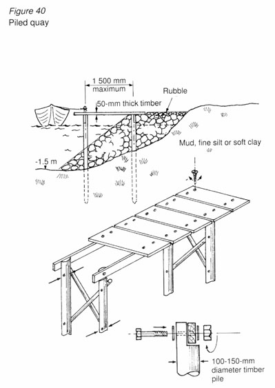
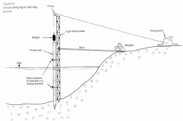
Timber piles, 100 - 150 mm in diameter, should be driven into the mud using a pile driver similar to that shown in Figure 41.
The piles should be placed according to a 1 - 1.5-m grid
depending on the size of the piles and timber beams available.
The quay is then finished by anchoring timber beams from pile to
pile along the length of the quay. Planks can then be attached to
these beams to make a wooden deck.
If a quay deeper than 1.5 m is required, two such
constructions should be built, one in front of the other. The
distance between the piles should never be greater than 1.5
m.
Once the piles have been driven into the ground, the shoreside
of the quay should be filled in with coarse quarry material. This
will increase the stability of the quay and prevent rotting
flotsam from being trapped between the quay and the shore.
All the timber used in this type of structure should be
treated against borers as described in Chapter 4.
All metal fittings should be galvanized steel (steel that has
been coated in zinc) or brass. Only countersunk screws and bolts
are suitable.
Nails should not be used in any part of the deck.
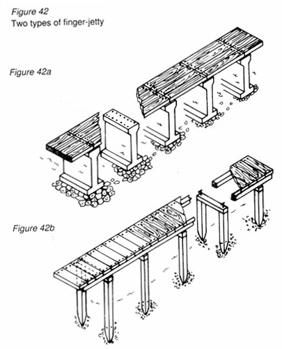
Figure 42 shows two typical concrete finger-jetties suitable
for areas of relative calm, such as in sheltered tidal beaches or
inside existing harbours.
If the concrete is made properly, a concrete jetty will
usually outlast a similar one built in timber.
Figure 42a shows a jetty suitable for areas with large tidal variations where pylons of simple mass concrete (that is concrete with no reinforcement) can be cast on a gravel bed at low tide. Precast reinforced concrete or plain timber decking is then anchored across the pylons to form the jetty.
If a piling rig is available, precast reinforced concrete piles, 300 x 300 mm, can be driven into the sea bed and beams cast across the pile heads as in Figure 42b. As for the pylon type of jetty, precast reinforced concrete or plain timber decking can then be anchored across the beams.
Chapter 4 gives details on the manufacture of durable marine concrete. Coral aggregate (stone and sand) is not suitable for steel reinforced sections. All the steel reinforcement used inside concrete sections (piles, beams or slabs) should be covered by at least 50 mm of concrete. All exposed fittings should be galvanized.
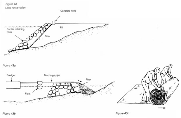
Figure 43 shows typical land reclamation. Figure 43a shows land that has been reclaimed by tipper trucks full of quarry waste and Figure 43b shows land reclaimed by dredger, see Chapter 5.
When reclaiming land from the sea using dredged or mined sand, great care should be taken to avoid polluting the sea with suspended dust. Fill material contains very fine dust and reclamation projects often give rise to plumes of suspended sediment in the sea around the construction area. These are harmful to certain forms of marine life, such as coral, that need bright sunlight to survive.
To prevent reclaimed material from leaching away into the sea it should be protected by geotextile filters (Figure 43c) of adequate porosity. The geotextile filter has to be anchored to the side of the reclaimed bank using weights (not pegs). The weights can then be incorporated into the retaining bank that consists of carefully placed stones weighing at least 500 kg.
Each patch of geotextile filter laid should either be stitched to or overlap the previous patch by at least 300 mm. Punctured filter should be repaired prior to being placed.
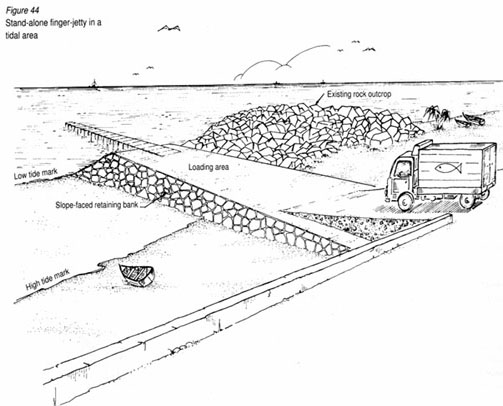
Figure 44 shows a stand-alone finger-jetty in a tidal area. The solid part of the jetty (the loading area) should not project beyond naturally occurring obstacles, such as rocky outcrops.
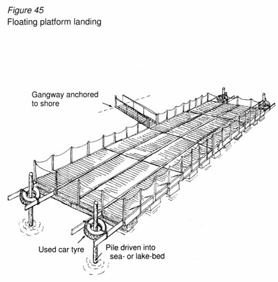
Figure 45 shows a floating platform anchored in position by four vertical piles and connected to dry ground by a gangway pivoted to a frame. The platform rises and falls with the tide.
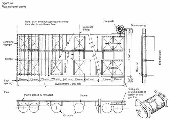
Figure 46 shows a floating platform made from empty oil drums and timber sections. Chapters 4 and 8 tell you how to protect timber and steel that are immersed in water. In areas where water-levels vary considerably over long periods of time, such as on lakes where water levels may take several weeks to change noticeably, a different anchoring system is required.
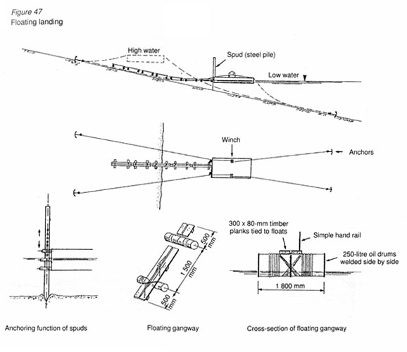
Figure 47 shows a floating platform for such conditions. It is held in place by four anchors and two "spuds" (steel piles). Two mooring lines run from the two anchors on land, pass over the platform, through a hand-operated winch and connect up to the remaining two anchors in the water. In this way the platform can be winched out as the water level drops and the shoreline recedes from its original position. The platform should be connected to the shore by a series of interconnected gangways that either float on the water or come to rest on the dry bed as the water level drops.
The platform should be equipped with at least two spuds to prevent it from swaying during high winds or strong currents. Each spud should consist of a heavy, pointed, steel pipe with holes drilled every 300 mm. Grips can be inserted in the right position to hold the platform steady as the water level changes. The spuds can then be lifted off the bottom until the platform is repositioned in deeper water when they can be dropped again; their pointed tips will stick into the lake-bed, holding the spuds in position.
The anchors should be placed as far away as possible from the
platform. The distance between the anchors and the platform
should be at least five times the depth of the water below the
platform. For example, if the water below the platform is 4 m
deep, the anchors must be dropped at least 5 x 4 m away, that is
20 m away.
The anchors should preferably be made of steel and weigh as much
as is possible to handle without the aid of cranes.
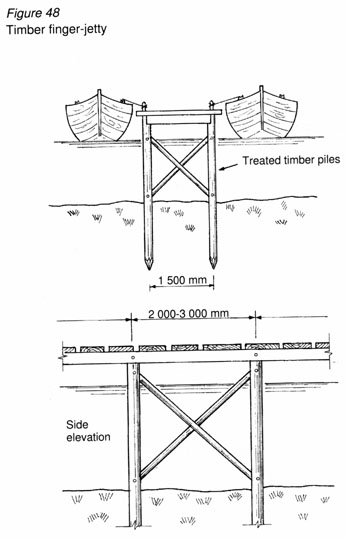
Figure 48 shows a typical timber finger-jetty on piles, with boats moored on both sides.
The piles can be made of timber, steel or reinforced concrete. Ideally, the deck should be built in timber or concrete.
The traditional slipway in many small beach side communities is still the natural beach where boats are hauled ashore for scrubbing, cleaning and repair. However, in a harbour or where there are no large tides, a beach is not always practical and a manmade slope or slipway is required.
In a harbour, a typical slipway consists of an opening in the
quay wall over which a solid smooth surface is cast in
concrete.
Ideally, the slipway should not be less than 5 m across and the
slope not steeper than 10 percent (that is a slope of 1/10). The
tip of the slipway should dip at least 1.5 m into the water as
shown in Figure 49. To build a slipway, a bed of fine
stonechippings or gravel should first be laid to the required
slope. From mean sealevel up to the top of the slope, the slipway
should be covered by a concrete cast in one slab, 300 mm thick.
From mean sea level down to the tip, the slipway should be
covered in precast concrete slabs, at least 250 mm thick. The
precast slabs should not exceed 500 x 500 mm and care should be
taken to lay them evenly on the prepared bed of gravel. The tip
of the slipway should be protected, against scouring, by
concrete-filled jute bags. If boat trailers are not available for
launching the vessels, timber sections of 150 x 150 mm should be
laid down and bolted to the concrete slope to act as a rubbing
surface for the boats' timber keels. Figure 50 shows the typical
dimensions for the interlocking precast slabs required for laying
underwater.
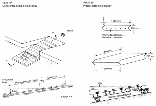
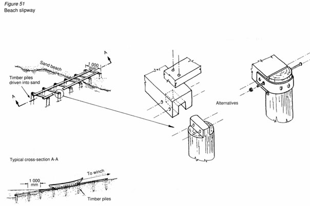
Figure 51 shows how a permanent slipway should be built on a sandy beach. Timber piles are driven in two straight lines at 500 mm intervals. Chapter 4 describes in detail the types of timber suitable for immersion in water. Wooden sleepers are then screwed into the piles with heavy duty screws in stainless steel or brass. Light rails or timber runners should then be attached to span across the sleepers for a trolley to run up and down the slipway.
To haul the vessels up the slope, a hand operated 1 - 2-tonne winch is usually sufficient. The winch should be bolted to a block of concrete (separate from the slipway slab) at least 500 mm thick.
![]()
![]()
![]()