![]()
![]()
![]()
An adequate supply of good quality water is a fundamental requirement for fishery harbours, whether the water is used for drinking, cleaning the fish, ice making or fish processing. Where municipal supply of potable water is limited, other sources need to be investigated - including the use of harbour basin water or sea water for certain uses.
To plan the water supply system for a fishery harbour, it is necessary to estimate the peak demand for water which is a direct function of the peak landings; the number of fishing vessels using the harbour; the number of port staff and crew, and harbour facilities like canteens, ice plants and processing plants. The following table may serve as a guide for estimating water requirements.
Table 3-1: GUIDELINES FOR ESTIMATING WATER REQUIREMENTS
|
Activity |
Quantity Required |
|
a. Fish rinsing |
1 l/kg of fish landed |
|
b. Auction hall cleaning |
10 l/m2 of floor area |
|
c. Fish boxes cleaning |
10 l/box |
|
d. Personal hygiene |
100 l/person |
|
e. Canteens |
15% of item (d) |
|
f. Vessel supply |
30 l/person/day |
|
g. Ice |
1 kg for 1 kg of fish landed |
The gross daily volume for item (a) should be increased by 25% to cover seasonal peaks and volume for items (b) and (c) may be reduced by 50% if high pressure cleaning systems are used.
Some common sources of water in fishery harbours are from borewells, rain water collection tanks and pumped sea water. Recent advances in desalination equipment to convert sea water to potable water constitute an option worth investigating.
The geological investigation of the sub-strata is generally carried out by a specialist sub-contractor. More than one borehole may be required for complete assessment and the depth need not depend on the local water table. There are instances where shallow borewells may produce contaminated or brackish water, and a deeper well taps into a submerged freshwater aquifer. The major geo-technical requirement is to verify the porosity of the substratum as this will determine the maximum rate of extraction of water. In coastal areas, over-extraction of fresh water from the underground water table has often caused the water to become saline through intrusion of sea water.
Figure 16: WATER SUPPLY SCHEME FOR AN ARTISANAL LANDING
When sea water is used for cleaning purposes, care should be taken to avoid sea water runoff entering the sewage treatment system. The pumps should be suitable for sea water. Sand excluding filter is required for sea water suction from sandy beaches.
Figure 17: REPLACEMENT OF POTABLE WATER WITH SEA WATER FOR SOME SERVICES
Figure 18: TYPICAL PUMPING ARRANGEMENTS FOR EITHER SEA WATER OR POTABLE WATER
Desalination: Desalination may be carried out in two ways: flash distillation of sea water or reverse osmosis. Flash distillation is relatively inexpensive if heat from a generator can be extracted via the circulating cooling system of the diesel engine. Typically, the system consists of a spherical steel container connected to a vacuum pump with heating coils circulating hot water from the engine's cooling system. The vacuum pump lowers the boiling point of water, thus making the sea water boil. Potable water is distilled off from the top and pumped to a storage tank. The major disadvantage is the frequent descaling required to remove encrustations in the distilling tank.
The preferred method of desalination nowadays is by reverse osmosis. This process consists of pumping sea water at very high pressure against a special osmotic membrane rolled up inside a steel cylinder. The membrane allows only fresh water to pass through. This system is relatively expensive to operate but in arid areas may be the only viable option. Small reverse osmosis plants are now commercially available and the following table illustrates some of their basic characteristics.
Table 3.2: TYPICAL CHARACTERISTICS OF REVERSE OSMOSIS PLANTS
|
Feedwater |
Operating pressure |
Power requirement |
Water production |
|
bar |
kw |
m3 per day |
|
|
Brackish |
45 |
5.0 |
12.5 |
|
Brackish |
45 |
11.0 |
100.2 |
|
Sea water |
56 |
18.2 |
45.6 |
|
Sea water |
56 |
37.1 |
91.2 |
The above figures refer to brackish water with 2000 ppm and sea water with 35000 ppm of sodium chloride. Operating temperature is 25 deg. C. For every deg. C drop below 25°C, the efficiency drops by 3 %. The membrane is very sensitive to suspended solids.
The type of water storage facility depends on the quantity to be stored as tabled below.
|
STORED CAPACITY |
TYPE OF STRUCTURE |
|
Upto 1 m3 |
Plastic or steel drums, single or in parallel connection, usually used as header tanks only and placed above a ground reservoir |
|
Upto 5 m3 |
Steel or concrete tank construction, usually serve as small overhead storage tanks, gravity feed |
|
Upto 80/100 m3 |
Concrete or steel overhead storage tanks, gravity feed |
|
Above 100 m3 |
Above ground or underground reinforced concrete reservoirs, requiring header tanks |
Figure 19a: LARGE CAPACITY ABOVE-GROUND REINFORCED CONCRETE WATER RESERVOIR
Figure 20: A TYPICAL MODERN STEEL OVERHEAD TANK USING BRAITHWAITE PRESSED-STEEL PANELS
Whether an ice plant is actually required inside the port area depends very much on local conditions. Other ice plants in town may be a reliable source of suitable ice and, even with the additional transport costs and the manufacturer's profit thrown in, they may be able to supply ice cheaper than it can be made by the user. A large installation has many economic advantages over a small unit and it is not unreasonable to expect that it can produce cheaper ice. Other factors, such as being financially self sufficient, may over-ride an economic disadvantage.
In addition to water supply and storage, a harbour manager should also be conversant with the manufacture, supply and storage of ice as this product, if contaminated at source (either through contaminated water supplies or through human contact during the manufacturing process), has the potential to contaminate entire fish landings; see also Chapter 2. Contaminated ice has been linked to serious outbreaks of cholera in at least one ASEAN country.
Table 3-3: GUIDELINES FOR ESTIMATING ICE REQUIREMENTS
|
ACTIVITY |
QUANTITY REQUIRED |
|
Onboard, trip greater than 1 week |
1.0 T of ice per 2 Tons of fish (temperate waters) |
|
Onboard, trip less than 1 week |
0.7 T of ice per 2 Tons of fish (temperate waters) |
|
Onboard, short duration |
1.0 T of ice per 1 Ton of fish (tropical waters) |
|
Auction hall, re-packaging |
1.0 T of ice per 1 Ton of fish (hot climates) |
Ice is usually manufactured in block, flake or tube form.
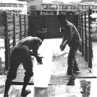
The traditional block ice maker forms the ice in cans which are submerged in a tank containing circulating sodium or calcium chloride brine. The dimensions of the can and the temperature of the brine are usually selected to give a freezing period of between 8 and 24 hours. Too rapid freezing results in brittle ice. The block weight can vary from 12 to 150 kg, depending on requirements; 150 kg is considered the largest size of block one man can conveniently handle. The thicker the block the longer the freezing time. Blocks less than 150 mm thick are easily broken and a thickness of 150 to 170 mm is preferable to prevent the block toppling. The size of the tank required is related to the daily production. A travelling crane lifts a row of cans and transports them to a thawing tank at the end of the freezing tank, where they are submerged in water to release the ice from the moulds.
The cans are tipped to remove the blocks, refilled with fresh water and replaced in the brine tank for a further cycle. This type of plant often requires continuous attention. A shift system is operated by the labour force - 10 to 15 workers for a 100 t/day plant. Block ice plants require a good deal of space and labour for handling the ice.
The latter factor has been the main reason for the development of modern automatic ice-making equipment (flake and tube ice). Compared to other types of ice plants, block ice plants are more prone to producing contaminated ice if high hygiene standards are not scrupulously observed at all times.
Block ice still has a use, and sometimes an advantage, over other forms of ice in tropical countries. Storage, handling and transport can all be simplified if the ice is in the form of large blocks; simplification is often obligatory in small-scale fisheries and in relatively remote situations. With an appropriate ice-crushing machine, block ice can be reduced to any particle size but the uniformity of size will not be as good as that achieved with some other forms of ice. In some situations, block ice may also be reduced in size by a manual crushing method.
This type of machine forms ice 2 to 3 mm thick on the surface of a cooled cylinder and the ice is harvested as dry subcooled flakes usually 100 to 1,000 mm2 in area. In some models, the cylinder or drum rotates and the scraper on the outer surface remains stationary. In others, the scraper rotates and removes the ice from the surface of a stationary drum, in this case built in the form of a double-walled cylinder. One distinct advantage of the rotating drum method is that the ice-forming surfaces and the ice release mechanism are exposed and the operator can observe whether the plant is operating satisfactorily. The flakes are usually either bagged directly in plastic bags and stored in a chiller or collected and stored in an automated bin or silo. Human contact with the ice is minimal. The range of unit sizes for this type of machine now extends from units with a capacity of 0.5 to 60 Tons/24 h.
Figure 21: SELF-CONTAINED FLAKE ICE MAKER WITH BIN STORAGE
Tube ice is formed on the inner surface of vertical tubes and is produced in the form of small hollow cylinders of about 50 x 50 mm with a wall thickness of 10 to 12 mm. The tube ice plant arrangement is similar to a shell and tube condenser with the water on the inside of the tubes and the refrigerant filling the space between the tubes. The machine is operated automatically on a time cycle, and the tubes of ice are released by a hot gas defrost process. As the ice drops from the tubes a cutter chops the ice into suitable lengths, nominally 50 mm, but this is adjustable. Transport of the ice to the storage area is usually automatic. Thus, as in the flake ice plant, the harvesting and storage operations require no manual effort or operator attendance. Tube ice is usually stored in the form it is harvested, but the particle size is rather large and unsuitable for use with fish. Self-contained units, Figure 21, with a rating of up to 10 to 20 tonnes/24 hours can be located within the floor space required for storage, with the icemaker and refrigeration equipment on top.
Ice manufacture and demand rates are seldom in phase, therefore storage is necessary to ensure that the plant caters for peak demand. Storage allows the ice maker to be operated 24 hours per day. It also acts as a buffer against any interruption to the ice supply due to minor breakdowns and routine maintenance procedures. There is no general rule for estimating ice storage capacity requirements.
Table 3-4: STORAGE REQUIREMENTS FOR VARIOUS TYPES OF ICE
|
TYPE OF ICE |
STORAGE SPACE (m3 per Ton) |
|
Flake |
2.2-2.3 |
|
Tube |
1.6-2.0 |
|
Crushed block |
1.4-1.5 |
Block ice cannot be stored in silos or bins unless the ice is crushed beforehand. This type of ice is therefore stored in block form in refrigerated rooms.
Refrigerated rooms should be professionally designed and constructed so as not to allow contact of the stored ice with unauthorised persons or domestic animals. The floor should be a seamless-type floor with no cracks or joints. Persons handling the ice in the store should wear rubber boots and gloves.
A conventional block ice plant would also have a considerable amount of extra storage in the ice making unit, since it is usual to maintain the ice cans filled, even when demand has fallen below the plant's rated capacity.
Bin storage may mean anything from a box holding no more than 500 kg to a large installation of 1,000 tons or more. Bin storage can be used for any type of ice and may incorporate a separate cooling system. Whatever the size of system used, ice storage should always be within an insulated structure since the saving made by reducing ice meltage, particularly in warmer climates, is always worth the extra cost of the insulation. An insulation thickness of 50 to 75 mm of polystyrene or its equivalent in one of the many other suitable types of insulation, is suggested. Small bins may be arranged with the icemaker above the storage space, Figure 21; the bin is filled by gravity and a FIFO system is operated by removing the ice at a low level. This simple bin system is suitable for processors making and using their own ice.
Bins of up to about 50 tons capacity can be constructed without a mechanical unloading system. This type of storage would usually be a high structure with a sloping base and access to dislodge compacted ice. Any ice left undisturbed for a few days will compact and fuse together. Ice which is free flowing when used daily may require a mechanical unloading system if used infrequently.
Silo storage is generally used with a free-flowing subcooled ice such as flake ice and, in order to be effective, it must have an independent cooling system to maintain the ice in this subcooled condition. The cooling is usually by means of an air cooler in the jacket space between the silo and the outer insulated structure. The air cooler is normally placed at the top of the jacket space adjacent to the ice maker and the air space is cooled by gravity or fan circulation. Ice is collected by gravity flow with the aid of a chain agitator which scrapes the ice from the walls of the silo. The silo allows for a first-in-first-out (FIFO) system of storage but, if the storage space is not cleared periodically, only the central core of ice is used, leaving a permanent outer wall of compacted ice, Figure 22. An access hatch should therefore be provided at the top of the silo so that a pole can be inserted to collapse the outer wall of ice into the central core at least once daily. Silo storage is expensive for small quantities of ice and although units are made for as little as 10 tons, this method of storage is more suited for storing 40 to 100 tons of ice.
Figure 22: TYPICAL ICE STORES
Figure 22a: Silo ice store with a swing chain agitator
Figure 22b: Bin ice store with ice maker on top
Figure 22c: Ice store with raker
![]()
![]()
![]()