![]()
![]()
![]()
4.1 Harbour wastes
4.2 Waste audit
4.3 Non toxic solid wastes
4.4 Toxic solid wastes
4.5 Dredging spoils
4.6 Oily waste and oil spills
4.7 Sewage and effluent treatment
4.8 Fish offal
The fishery harbour complex is a hub of activities with nearly all of them being potential waste generators. In the absence of adequate facilities for collection, treatment and disposal systems, these wastes will pollute the harbour complex and the harbour waters. Floatable material may escape from the area and end up along the coastline and beaches causing further damage to ecology and aesthetics.
Pollution from harbour-generated wastes can be categorized as those that cause:
· visible pollution of land and water by oil spills and sewage;
· invisible pollution of harbour water by hazardous wastes; and
· degradation of the harbour environment by discarded litter and fish offal.
Typically they may be further categorized as:
· non-toxic solid waste including flotsam washed into the harbour;
· toxic solid waste;
· dredging spoils;
· oily waste including accidental oil spills;
· sewage and grey waste; and
· fish offal and blood water.
In the past the approach to waste management was to look at wastes as an 'end-of-the-pipe problem' and adopt appropriate treatment technologies. While some form of such treatment may be required, it is often far more practical and cost-effective to minimize the amount of waste generated in the first place. Waste minimization is achieved through the practice of the '3 R's' - reduction, reuse and recycling.
Reduction refers to minimizing the amount of waste generated from a given operation or process. It is accomplished by using less polluting materials in place of highly polluting ones; implementing processes that generate less waste; and good operating practices. In fact, source reduction is really not about managing waste, but about managing the raw materials more carefully in the first place.
Reuse refers to using the waste material 'as is' - such as using waste oil for fuel.
Recycling refers to reclaiming materials from the waste product such as scrap metal recycling or transforming waste plastic or paper into new products. There are many benefits from recycling. It reduces the amount of waste for disposal; saves natural resources; and provides jobs for scrap collectors and dealers.
In a fishery harbour complex, the harbour master should perform a 'waste audit'. This is a management tool that enables him to evaluate policy and remedial actions. The audit should help identify the source, quantity and concentration of all waste streams. It should then be possible to evaluate from practical and cost considerations which of the '3 R's' or disposal is most suitable for the fishery harbour complex with a given set of local conditions.
The fishery harbour complex has many activities within the complex and each of them may be a point source of waste. The harbour master should group the harbour area into zones according to the activity performed in each zone and analyse them individually for the kind of waste generated; the probable quantities; and the method of disposal. The table below lists typical harbour activities and the wastes associated with them. Estimating the quantities is a matter of judgement based on existing practices.
Table 4-1: TYPICAL WASTE STREAMS
|
Zone |
Source |
Waste generated |
|
Harbour basin
|
Fishing vessels
|
Bilge water |
|
Lube oil |
||
|
Sewage |
||
|
Toilet waste |
||
|
Kitchen waste |
||
|
Deck washing |
||
|
Fish hold cleaning |
||
|
Fishing vessels and Current |
Floating garbage |
|
|
Landing jetty/Marketing
|
Auction hall
|
Fish waste |
|
Blood water |
||
|
Trash fish |
||
|
Hose down water |
||
|
Gutting area
|
Fish offal |
|
|
Hose down water |
||
|
Fuel pump |
Oil leaks |
|
|
Main complex
|
Toilets
|
Sewage |
|
Waste from wash areas |
||
|
Canteen
|
Kitchen waste |
|
|
Waste from wash area |
||
|
Litter and food scraps |
||
|
Boat repair
|
Oil and grease |
|
|
Paint cans, paint |
||
|
Anti-fouling paint cans |
||
|
Used batteries |
||
|
Torn nets and rope |
||
|
Wood shavings, steel scrap |
||
|
Offices |
Toilets and Garbage |
We shall now look at the above wastes in terms of their classification and suggested disposal.
4.3.1 Reduction
4.3.2 Recycling
4.3.3 Collection
4.3.4 Disposal
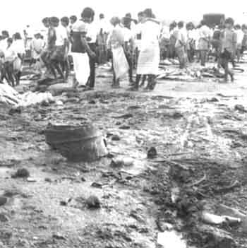
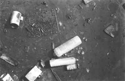
Typical non-toxic wastes in a fishery harbour include paper, plastic bags, plastic containers, metal containers, old tyres, pieces of rope, bits of netting, food wrappers, bottles, fruit peels and flotsam like driftwood, generally termed as litter. This type of waste not only makes the harbour look dirty, it can clog drains, foul boat propellers, choke water intakes and so on. Some of the waste may be biodegradable and the rest non-biodegradable.
Figure 23: DISCARDED NON-TOXIC WASTE
Probably the key to minimizing this waste is to encourage the use of products that need less packaging or buying in bulk. For instance, if the fishery harbour supplies engine oil to boats, it may be better to buy one 50-litre can instead of 50 one-litre cans.
Many of the waste items can be recycled. This involves collecting and sorting the discarded materials suitable for recycling. Paper, plastic, glass and aluminium cans can be recycled. Wet organic matter can be converted into compost. In Thailand, old tyres are converted into garbage bins.
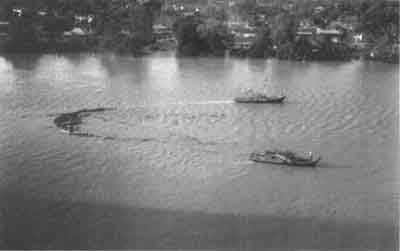
The harbour master must ensure that adequate containers are strategically placed within the harbour complex for collecting the litter. It is advisable to have separate containers to facilitate the segregation of waste into recyclable dry waste, wet organic waste that can be composted and hazardous waste which needs special care in disposal. Floating garbage is best collected by small boats using a scoop net or as the figure below shows, two vessels working together using a floating net boom.
Figure 24: Two vessels towing a floating boom and net across the river to collect floating debris
The type of garbage skips and receptacles depends on the method of solid waste handling by the municipality in the area. Garbage receptacles may be custom-made if a compacter truck is used for collection of heavy duty plastic or galvanized steel. The size should take into consideration whether the receptacles are manually emptied into the collection truck. It is often the case that large concrete bins overflow with garbage as the accumulated garbage makes it unpleasant for those emptying them. Plastic receptacles, if used, should be u-v stabilized or protected from direct sunlight. Steel containers should be galvanized.
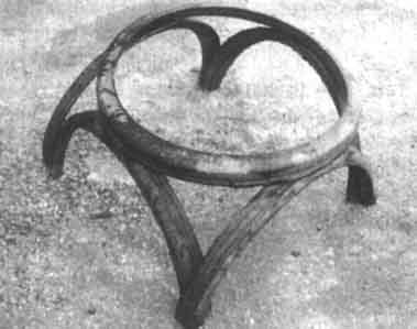
Figure 25: GARBAGE RECEPTACLE MADE LOCALLY FROM OLD TYRES
The stand of a local tyre garbage bin made from used truck tyres
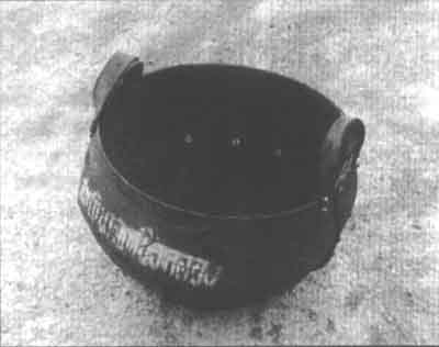
Figure 26a: THE RECEPTACLE FROM THE PREVIOUS FIGURE SHOWN ON ITS STAND
Figure 26b: DISCARDED PLASTIC CHEMICAL BARRELS RE-UTILISED AS RECEPTACLES
Figure 27: EXAMPLES OF CUSTOM-MADE RECEPTACLES
Wire naslet
Mobile/plastic supercan
Wooden/metal outer container with lid

Outer container with raised cover
Metal barrel
Metal with lid
Plastic
Figure 28: EXAMPLES OF RECEPTACLES TO STORE WASTES IN HARBOUR AREAS
Mobile/Stationery dumpster with lid
Eventual disposal of solid wastes is usually the responsibility of the municipality. The harbour master should take all steps to meet the municipality requirements for collection and schedule. In some harbours, private garbage collectors are contracted to transport the harbour garbage to selected sites serviced by the municipality.
Figure 29: TRANSPORTATION BY TRUCK TO COLLECT WASTES
In the event that the garbage is to be disposed of by the fishery harbour on its own, the practice of open dumping of solid wastes should be discouraged. Garbage which is neither compacted nor covered smells foul and attracts flies and rodents. Domestic animals feeding at such a dump can catch and spread diseases. Leachate and rain runoff can contaminate land and water sources nearby.
Landfills are considered better alternatives. Here, large earth-moving equipment compact the garbage and cover it with a layer of soil. Each day's garbage becomes a buried cell. Leachate from a landfill can be also be hazardous when such landfills are located in wetlands and areas with porous soils since ground and surface water can be polluted by it. To overcome this problem, a landfill is made 'sanitary' by lining it first with an impermeable material. This can be expensive and cannot guarantee leachate from leaking out. With rapid urbanization, suitable landfill sites are becoming scarce, leaving no option for solid waste disposal other than incineration. Figure 30 shows a typical cross-section of a sanitary landfill.
Figure 30: LANDFILL DOUBLE COMPOSITE LINER
Figure 31 below, shows a typical cross-section of an industrial type incinerator.
Figure 31: A TYPICAL CROSS-SECTION OF INCINERATION PLANT
Incineration, though advocated by some as suitable for energy recovery in the form of heat, has its own drawbacks. Burning waste is not a clean process. It produces air and water pollution and tons of toxic ash. The more sophisticated plants have filtering devices to reduce this pollution and can be very expensive.
Empty paint cans, used containers of antifouling paint, dry cell batteries, and containers of paint stripper are all forms of toxic waste encountered in a fishery harbour complex. The same waste management methods of reduction, reuse, and recycling are applicable though recycling possibilities may be few. Separate receptacles must be provided for toxic wastes. Disposal of toxic wastes should be left to competent authorities. If a medical dispensary is located within the harbour complex, care should be taken not to mix hospital wastes with the general wastes.
Spent lead batteries can be reconditioned, or the lead can be recovered even at the village level by local smelters and put to other uses like lead sinkers for fishing nets. However, precautions are needed to ensure safety for the worker and to prevent careless dumping of the spent acid, thereby moving or accelerating the pollution towards groundwater.
Figure 32: TYPICAL HAZARDOUS WASTE ITEMS
Lead-acid batteries
Disposable batteries
Paint containers

Engine oil containers
Oil filters spark plugs
Cotton wastes

The harbour basin may need dredging from time to time due to siltation. Disposal of dredging spoils at sea, if not carefully planned, can be damaging to the marine environment - affecting fish life and fragile organisms like corals if native to the area. Discolouration of nearshore water could result in adverse effects on beach recreation and tourism. Dredged material can be put to better use when used for land reclamation of low-lying coastal land, if it is not contaminated.
Dredging spoils from the harbour basin may be contaminated by sewage, oils and heavy metals from workshops and other industry around the port area. It is therefore advisable to dump such waste into an established dump site away from known fish breeding and fishing areas. Such a site is usually where seabed currents are low and do not allow dispersal of contaminants in the water column.
4.6.1 Oily wastes
4.6.2 Minimizing bunkering leaks
4.6.3 Coping with oil spills
Oil pollution occurs in harbour basins when leaks from shore facilities for the supply of diesel fuel to fishing vessels find their way into the harbour water; when vessels pump out oily bilge water in port; when used engine oil is dumped overboard and when an accident results in leakage of fuel oil. A fishery harbour which is contiguous with the main harbour also faces the risk of major oil spills if the main port is a transfer point for crude oil or refined products from oil tankers.
To mitigate oil pollution, the fishery harbour manager should take necessary action to:
· Provide shore-based reception facilities for oily wastes (bilge water and spent oil) from vessels and· Minimise leaks while bunkering.
In addition, he should be prepared to assist those responsible for containment and clean-up operations if a major oil spill occurs in the vicinity. Appropriate oil recovery tools like skimmers will prove useful in removing spilt oil from the harbour basin.
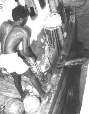
Figure 33: A TYPICAL SCENE INSIDE A FISHING HARBOUR - BILGE WATER BEING PUMPED OVERBOARD
If adequate shore-based facilities are not available for receiving oily wastes, vessels will in all probability dump wastes overboard, as Figure 33 glaringly demonstrates.
Oily wastes discharged to reception facilities are usually mixtures of oil and water and in some cases, solids. The composition ratio of these solids can differ considerably, depending on the type of wastes; bilge water consists mainly of water contaminated with oil, whereas waste oil and fuel residues consist mainly of oil contaminated with water.
Figure 34a: Artisanal oil/water separator
Figure 34b: Separated bilge oil collection
Figure 34c: Cross section of a typical oil-separation and storage facility for fishing ports
Figure 34a illustrates an artisanal oil separator for bilge water. Figure 34c shows a commercial size oil separator which can achieve very low concentrations of residual oil in the discharge water (5 parts oil per million parts water).
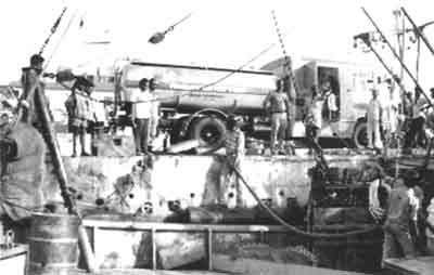
Figure 35a: THE 10 m3 MOBILE RECEPTOR FOR BILGE WATER AT VISAKHAPATNAM, INDIA
Figure 35b: THE 1 m3 MOBILE RECEPTOR FOR BILGE WATER AT PHUKET, THAILAND
The oil collected by the separators may then be returned to a recycling plant by authorised collectors. In Visakhapatnam, India, the main port has a fixed installation of 100 m3 capacity to service cargo ships and an 8 m3 mobile tanker to collect oily bilge water from some 100 fishing vessels ranging from 15 to 25m in length. The mobile tanker is fitted with a vacum pump and an oil-resistant hose to span four vessels moored abreast. In Phuket, a much smaller mobile tanker (1 m3) was used for collecting oily bilge water.
Reception facilities for used engine oil inside harbours are intended as a temporary storage only, whereas the reception facilities for bilge water need to separate the oil from the considerably larger volume of water. The oil may then be transferred to the used oil storage facilities for collection at a later date, and the treated water returned to the sea. Waste or spent engine oil can be recycled 100 per cent and it is now very common for refineries to collect used oil from harbours, car repair shops and petrol stations.
Figure 36a: Artisanal spent oil collection system
Figure 36b: Authorised artisanal collection
Figure 36c: A 5000 litre spent oil tank for a small fishing port
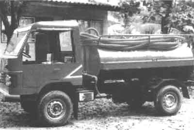
Figure 36d: Collection by road tanker
Figures 36a to 36d show how spent oil may be collected and stored in artisanal and commercial fishing ports. For a small-to-medium sized port, a large single tank is preferable, typically a 5000 litre tank, placed inside a containment tray in concrete.
Refueling facilities in fishing harbours may vary from small artisanal units to large commercial installations. In an artisanal refueling facility diesel could be supplied from 200 litre steel drums, as shown below in figure 37a. On a larger scale, for instance by a co-operative society, a large steel tank with a capacity of 5000 litres is usually installed away from the jetty. This tank is connected to a quayside fuel pump. In larger harbour installations, proper fuel storage tanks should be constructed as per the specifications laid down by the American Petroleum Institute and known as API Standard 650.
Figure 37a: Individual artisanal refueling facility
Figure 37b: Co-operative refueling facility
In all cases the harbour master must ensure that there are no leaks from such installations. He must ensure that gravity feed systems are restricted to small artisanal drums only and that the entire refueling system is contained inside a concrete containment tray. He must also ensure that in larger co-operative systems, all fuel delivery is via pumps (not gravity feeds) and that the fuel tank is inside a concrete containment tray that can hold the entire contents of the tank.
4.6.3.1 Mechanical containment
4.6.3.2 Mechanical recovery of oil
4.6.3.3 Dispersant use
Oil contamination is highly visible, whether in the form of oil slicks or tarballs in harbour basins and coastal waters. The potential effect of oil spills on commercial fisheries - particularly the loss of marine habitats - is a matter of serious concern. Oil pollution can even lead to closure of fisheries, through potential impact on human health, tainting of seafood and fouling of fishing gear.
Tanker accidents are the best-known cause of oil pollution. But the most common cause is spills during terminal operations. Because they occur close to the shore and often in a confined area such as ports, their environmental damage to the immediate vicinity can be considerable. These areas are highly productive biologically, and provide shelter for many marine organisms at sensitive young stages. The fact that in many parts of the world, especially south-east Asia, they are also sites of extensive aquaculture, emphasizes the importance of protecting them.
When a major oil spill occurs in the vicinity of the fishery harbour, it is expected that the harbour master will render assistance to the team responsible for combating the spill and for subsequent clean-up operations. He is expected to have a basic understanding of the dynamics of oil spills and be conversant with the tools used for containment and clean-up operations.
On leaking or spilling into the sea, oil is subject to a series of processes that distribute the product in the environment and at the same time cause it to age or gradually convert, thus changing its physical and chemical characteristics.
Spreading: After the spill, oil spreads over the water surface in the form of a thinning film. In the case of most spills, slick size is generally controlled after the first hour or two, by a surface tension-viscosity relationship which is independent of spill volume. Spreading competes with emulsification. Emulsification greatly increases the viscosity of the remaining slick, reducing the tendency to spread.
Evaporation: This is a process by which low-to-medium molecular weight components of relatively low boiling point evaporate into the atmosphere. Components with boiling points lower than 200°C will evaporate within 24 hours. The loss of more volatile components will cause the remaining oil to have a higher viscosity.
Solution: This is a process by which low molecular weight compounds are lost by the oil to the water. These products are then available for uptake by marine organisms and can be toxic.
Emulsification: When small drops of oil are dispersed into water due to turbulence in the water, an oil-in-water emulsion is formed. This has a much higher viscosity than the original oil. After prolonged weathering, the emulsion becomes highly viscous and is commonly referred to as 'chocolate mousse'.
Sedimentation: When mixed with particulate matter like sand or silt, the oil eventually settles to the bottom;
Microbial degradation: Over 90 species of micro-organisms capable of degrading oil by biological oxidation have been identified. Biological degradation increases rapidly when nutrients like nitrates and phosphates are present.
There are four main methods of combating an oil spill:
· mechanical recovery;
· dispersant use;
· in-situ burning; and
· allowing the oil to come ashore for clean-up later.
Mechanical containment and recovery of oil is the most desirable option. Booms are used for containment, and skimmers are used to recover oil from the water surface.
Natural or induced agitation of water causes dispersion of oil into the water column. Dispersants are mixtures of surfactants in one or more solvents, specifically formulated to enhance the rate of this natural process and thereby reduce the amount of oil coming ashore.
In-situ burning has the advantage that it rapidly removes large volumes. But it poses fire hazards, and has limitations when the thickness of the oil slick is less than 2 mm. Emulsions bum poorly, if at all.
The last option of letting the oil come ashore is chosen only when the shoreline can be cleaned relatively easily or has low environmental, social or economic value.
Booms
Unless it is highly viscous or dense, oil when spilt will float and spread. Unless control measures are taken early, the slick will cover a wide area in a comparatively short time, making clean-up operations more difficult. To avoid this, booms can be used to prevent the spreading, and facilitate oil recovery.
Figure 38: An artisanal floating oil boom made from bamboo floaters, pieces of timber uprights and fish net filled with rice straw sorbent. The sorbent can be dried and incinerated ashore.
There are many kinds of booms. Their structure may differ, but basically they comprise the following components:
· freeboard to prevent or reduce splashover;· subsurface skirt to prevent or reduce escape of oil under the boom;
· flotation by air or some buoyant material;
· longitudinal tension member (chain or wire) to withstand the effect of winds, waves and currents.
Inflatable boom: These booms consist of inflatable air chamber or tubes. In most cases air is supplied from a low pressure blower but some are self-inflating. The skirt is made of oil and water-resistant fabric.
Figure 39: INFLATABLE BOOM
The advantages of an inflatable boom are that it has good wave-following characteristics and requires relatively little storage space. The disadvantages are that unless self-inflatable, it takes time to deploy and inflate. Rips and tears can cause loss of buoyancy.
Fence boom: A fence boom consists of a single sheet of material which constitutes both freeboard and skirt; floats and ballast weights are attached to it at intervals. Sometimes an external tension member is used to relieve stresses on the boom itself and this improves sea-keeping quality.
The optimum deployment of a boom will depend on weather conditions, the state of the sea and other factors. The following are typical deployment methods:
1. Encircling: This method may be employed in the early stages of spill control when discharge rate is low. The boom is deployed around the spill source, leaving a limited entry for workboats. If the spill is from a shore facility, the shoreline may constitute a part of the encircling barrier.2. Waylaying: Such a deployment is used for large oil spills, where sufficient lengths of boom are not available, or where encircling is difficult because of adverse weather and rough sea. Booms are laid at some distance from the spill source to intercept the approaching oil. In tidal waters, another set of booms may be laid on the other side of the source in anticipation of current reversing. (Figure 41).
3. Towing: If wind and current velocity are too high for stationary containment or if the oil is already widely scattered, booms can be towed at low speed (less than 0.5 m/s) through the water. (Figure 42).
4. Netting: This system consists of booms, buoys with anchors and weights laid upstream of the boom, and sheets of net. In cases where tarballs or mats are floating below the surface, nets are extended to the sea-bed from the skirt of the boom. Normally, this deployment method is used nearshore. (Figure 43).
5. Mooring: Booms may also be moored to conventional anchors or concrete blocks. Usually, mooring ropes five times the depth of water are required, and when ropes of buoyant material are used, this must be compensated for by adding extra chain or weights to the ropes.
Figure 41: WAYLAYING
Figure 42: TOWING
Figure 43: A NETTING OPERATION
Skimmers
There are several types of skimmers used to recover floating oil - such as drum, disk, belt or rope type skimmers. They may be installed in special collection vessels; be self-contained and portable for small spills in harbour basins; and even mounted on shore.
Belt-type skimmers are usually large and are installed in vessels. An endless loop of rubber belting transports oil and debris to the vessel. Pinch rollers separate the oil from the belt and the oil is stored in a collection tank.
Oleophilic ropes can also be used in a similar fashion (Figure 45). A loop of rope runs continuously across the water surface between a collection device which drives the ropes, and pulleys held by moorings. The ropes adsorb oil and carry it to a collection device where rollers squeeze the oil out of the ropes into a reservoir. Rope systems are unaffected by floating debris and can be used in very shallow waters.
Figure 44: EXAMPLES OF DIFFERENT SKIMMER TYPES
Figure 44a: Drum Skimmer
Figure 44b: Disk Skimmer
Figure 44c: Belt Skimmer
Figure 45: OLEOPHILIC ROPE SKIMMERS
In large harbours and for large slicks, specialized oil recovery vessels are used to skim the floating oil. They may be weir-type skimmers, adsorption separation type or induction type. The vessels have bow doors or ramps. Sweeping arms guide the floating oil-water layer into the vessel for separation and recovery.
Compact and portable disc skimmers can be deployed in harbour basins to get at oil films adhering to piers and harbour walls.
Figure 46: INDUCTION TYPE OIL SKIMMER
Figure 47: PORTABLE OIL SKIMMER
The hydrocarbon type of dispersants used in the past have had adverse effects on the environment due to their toxicity. Modem dispersants used today are significantly less toxic than the oils they disperse. They can be used either pre-diluted with sea water or in a concentrate form.
For concentrate dispersants, treatment ratios of 1 : 10 to 1 : 20 (dispersant : oil by volume) are needed. Under rough sea conditions, less dispersant may be needed.
The possible toxic effects of dispersed oil in the water column are a primary consideration when assessing the use of dispersants to deal with an oil spill.
Recreational areas for instance, may be of little value from the biological point of view, but they may be important for some local economies. In such cases, dispersants may be used relatively close to the shore.
In most cases, oil slicks will float over reefs without causing damage to submerged corals and associated organisms. Using dispersants close to the reef is likely to increase the exposure to oil, with possible damage to some of the organisms. Dispersant use over or near coral reefs should be avoided as far as possible.
In shallow water, dispersed oil in the water column is likely to reach concentrations where it may harm or taint fish. Dispersant use is generally not recommended in shallow water spawning and nursery areas.
The main points to remember are:
· Dispersing oil where there is sufficient water for dilution has no known toxic effects on marine or benthic biota; and· Toxic effects of using dispersant are possible when dilution potential is less, as in shallow bays or over coral reefs.
Figure 48: BOW SPRAY SYSTEM FOR DISPERSING OIL USING DISPERSANTS
4.7.1 Artisanal harbours
4.7.2 Other harbours
4.7.3 Wash-hand basin effluent
4.7.4 Market floor run-off
Untreated municipal sewage is perhaps the most common cause of water pollution when the sewage is discharged into it. Disposal of urban and industrial sewage is one of the most difficult problems in water pollution control. It is often feasible to use a submarine outfall to discharge waste effluents into unconfined coastal waters nearby, where the diluting and absorbing capacities of these waters greatly simplify treatment and disposal problems. But when the discharge is in confined waters, the risk of pollution is very high. Discharge into the harbour basin of raw sewage and grey waste from the harbour complex only exacerbates the problem.
The main problem with sewage pollution is the introduction of pathogenic microorganisms into the water body, thereby posing a health hazard to those who come into contact directly or indirectly with the contaminated water. The presence of faecal coliform bacteria is generally indicative of sewage pollution.
The serious threat to public health and financial losses on account of poor fish quality make it necessary for the harbour master to accord a high priority to monitoring water quality for signs of faecal pollution and for ensuring that sewage and gray waste from the harbour complex is adequately treated and safely disposed of. It is also necessary for him to interact with the municipality on issues relating to sewage pollution of contiguous waters.
To ensure that there is no pollution from sewage generated in the harbour complex, the harbour master should take steps to provide for proper collection and disposal not only from shore facilities but also from fishing vessels using the harbour. Adequate toilet facilities should be made available for harbour users. Defecation in the open by people and by animals near the waterside should not be tolerated.
Sewage effluent from a fishery harbour consists of:
1. Sewage from toilets;
2. Effluents from wash areas with detergents present; and
3. Effluents from fish cleaning operations.
The combined effluent from a fishing harbour should ideally be connected to a municipal sewer to be taken away and treated with normal household sewage. If such a sewer is not available within a reasonably economic distance, the effluent has to be treated before being discharged into a water course. Depending on the size of the fishing harbour, the effluent may be treated either via septic tanks and on-site natural treatment systems (artisanal harbours only) or via a proper sewage treatment plant (coastal, offshore and distant-water harbours). In both cases, adequate space should be provided for the purpose.
4.7.1.1 Slow rate treatment
4.7.1.2 Constructed wetlands - emergent plants
4.7.1.3 Constructed wetland - floating plants
4.7.1.4 Rapid infiltration
4.7.1.5 Which system is more suitable?
Artisanal harbours are more often than not situated in areas where the basic municipal infrastructure is very primitive or even totally lacking; introduction of sophisticated mechanical wastewater effluent treatment systems may also not be a viable option because of the costs involved. Natural treatment systems, on the other hand, may be designed to take advantage of the physical, chemical and biological processes that occur when water, soil, plants, micro-organisms and the atmosphere interact. The processes involved in natural systems include many of those used in sophisticated mechanical treatment systems, such as sedimentation, filtration, gas transfer, adsorption, ion exchange, chemical precipitation, chemical oxidation, and biological conversion and degradation - plus others unique to natural systems such as photosynthesis, photo-oxidation and plant uptake. In natural systems, the treatment process occurs at natural rates and tends to occur simultaneously in a single ecosystem reactor. In a mechanical system the processes occur sequentially in separate tanks at accelerated rates as a result of energy input.
Figure 49: TYPICAL LAYOUT OF AN ARTISANAL HARBOUR NATURAL TREATMENT SYSTEM

Figure 50: TRADITIONAL 3-STAGE SEPTIC TANK
The first stage of a natural treatment system is the septic tank, generally located in or around the harbour and into which all the effluent should be directed. A 3-stage septic tank is a rectangular underground chamber divided internally into three compartments.
After coarse screening through a basket sump, the effluent is retained inside the compartments for a minimum period of three days; during this period, the solids in suspension settle to the bottom of the first compartment where they are attacked and digested by bacteria. As a result, the volume of sludge is greatly reduced and the effluent clarified to some extent. Appropriate manholes should be provided over each compartment to enable sludge to be removed (pumped out) during maintenance.
The dimensions of the chamber should be such that peak total daily effluent flows are retained for a minimum period of three days inside the tank. Obviously, the larger the volume to be treated the larger the tank should be. Various methods are available to reduce the volume of water to be treated, such as high pressure jet cleaners for hosing down operations (largest consumer of water), automatic or spring-loaded taps over wash-hand basins and dual-flush action toilet flushing equipment.
The following guidelines may be used when calculating a harbour's total daily effluent flow rate.
Auction hall flow rate
1 litre per kg of fish landed every day;10 litres per square metre of covered area (reduced to 2.5 litres if a high pressure jet cleaner is used);
10 litres per fish box handled (reduced to 2.5 litres if a high pressure jet cleaner is used);
Toilet and shower facilities flow rate
100 litres per person per day (full time employees + part-time handlers and sellers + crew in port).
Canteen services (hot food cooked on premises) flow rate
15 litres per serving per day
This total volume should also be adjusted for peak summer conditions when fish handling and visiting crews increase in numbers. The effluent from the septic tank should then be piped for further treatment to one of several types of natural treatment systems. It should be discharged into a waterway or into the sea only as a last resort.
Natural treatment systems may consist of one of the following:
· Slow rate treatment (effluent is sprayed or channelled over vegetated land to provide treatment), Figure 51;· Constructed wetlands - emergent plants (effluent is fed into inundated areas that support growth of emergent plants such as cattail, bulrush, reeds or sedges), Figures 52a and 52b;
· Constructed wetlands - floating aquatic plants (effluent is fed into-inundated areas that support plants of the floating species such as water hyacinth and duckweed), Figure 53.
· Rapid infiltration (effluent is applied intermittently to shallow spreading basins and lost into the ground), Figure 54;
Figure 51: TYPICAL ABOVE-GROUND SLOW RATE TREATMENT FIELD
Slow rate treatment, the predominant natural treatment process in use today, involves the application of effluent or wastewater to vegetated land to provide treatment and to meet the growth needs of the vegetation. The applied water is either consumed through evapotranspiration or percolates vertically and horizontally through the soil profile. Any runoff is usually collected and reapplied to the system. This system needs a moderately slow soil permeability and in areas of high precipitation needs effluent storage. The effluent may be applied via sprinklers or furrows. Typical area requirements for this system are 15 to 45 acres per million litres of effluent per day.
Figure 52a: FREE WATER SURFACE FLOW TREATMENT
Two types of constructed wetland systems have been developed for wastewater treatment: free water surface flow systems, Figure 52a, and subsurface flow systems, Figure 52b. The water depth in this system is typically very shallow, ranging in depth from 0.10 to 0.60 metres. Subsurface flow systems are designed for secondary or advanced levels of treatment. These systems have also been called root zone or rock reed filters and consist of channels or trenches with relatively impermeable bottoms filled with sand or rock media to support emergent vegetation.
Figure 52b: SUBSURFACE WATER FLOW TREATMENT
This system is generally classified as a constructed wetland where the effluent may be collected after treatment and re-utilised in agriculture. Lack of a free water surface also makes it ideal for areas prone to mosquitoe infestation. Effluent storage is needed in areas of high precipitation. Typically, 4 to 14 acres per million litres of effluent treated daily are required.
Figure 53: FLOATING AQUATIC PLANT SYSTEM
Constructed wetlands offer all of the treatment capabilities of natural wetlands, but without the constraints associated with discharge to a natural ecosystem. Floating aquatic plant systems are similar in concept to free water surface systems except that the plants are floating species such a water hyacinth and duckweed. Water depths are typically deeper, ranging from 0.50 to 1.80 metres. Supplementary aeration has been used with floating plant systems to increase treatment capacity and to maintain aerobic conditions necessary for the biological control of mosquitoes. For this reason, the ponds should be stocked with mosquito fish. Area requirements are similar to other wetland systems.
In rapid infiltration systems, wastewater effluent is applied on an intermittent schedule usually to shallow infiltration trenches or spreading basins. Vegetation is not usually provided.
Figure 54a: SHALLOW SAND-FILLED FIELD TRENCH
The evaporative losses in this system are only a small fraction of the applied water. Hence, most of the applied effluent percolates through the soil profile where treatment occurs. The treatment potential of rapid infiltration systems is somewhat less than that for slow rate systems because of the lower retention capacity of the soil and the relatively higher inflow of water. In locations where the groundwater level is high (such as in coastal areas) or the underlying strata not permeable enough, pressure-dosed field trenches have been successfully used (Figure 54a). Pressure distribution, which serves to distribute the effluent evenly over the sand in the trench, is a key factor contributing to the success of this type of disposal.
The mound system (Figure 54b above), is essentially an intermittent sand filter that is placed above the natural surface of the ground. The effluent in this system is pumped from the septic tank through a piped pressure distribution system placed at the apex of the gravel layer. Mound systems have been used in areas where the soils are permeable and the water table very high or the soils not permeable at all. The system works well only if the water accumulated under the mound can be pumped away. This system requires mechanical pumping at all stages of the treatment and may not be suitable in areas which lack a steady power supply.
This question cannot be answered until the site has been evaluated by a competent geologist. However, the principal considerations in the design of a natural wastewater treatment system are:
· A preliminary site assessment;
· Detailed site evaluation;
· Assessment of the hydraulic assimilation capacity of the terrain;
The preliminary site assessment should consider the geomorphological features of the area, such as surface slopes, existing marshes or wetlands, flooding potential, groundwater extraction, water table levels and landscaping.
The detailed site evaluation should include identification of the soil characteristics, percolation coefficients and hydrogeological characterization of the area.
From these investigations it should be possible to determine the hydraulic assimilation capacity of the area, that is the suitability of the area to receive septic tank effluent without jeopardising the environment and public health (groundwater).
Fresh water should be utilised in the toilet flushing system when septic tanks are used for treating waste water. The presence of sea water (upto 30%) in the raw effluent decreases the efficiency of the bacterial decomposition of the sludge. Beyond 50% of sea water, bacterial decomposition is seriously compromised.
Other harbour installations, such as commercial fishing ports, situated away from municipal centres, should install proper sewage treatment plants which can handle a larger volume of water and produce an effluent which may be discharged directly into a water course. Depending on the required degree of purity of the effluent, a sewage treatment plant may consist of:
· Screening and disintegration (removal of major solids);· Sedimentation (to settle out organic solids into sludge);
· Biological filtration (over a pebble bed inside circular tanks);
· Tertiary treatment such as microstraining, aeration and upward flow rapid gravity sand filters.
Figure 55: TYPICAL MODERN SEWAGE TREATMENT PLANT
In small plants, screening for large solid matter which may interfere with pipe flow is generally carried out with manually racked bar screens at 60° to the flow. The rest of the organic solids are then macerated by means of a special pump and the fluid pumped into long sedimentation tanks; there, the drop in velocity allows some of the suspended matter to settle as sludge which is then removed periodically, dried and disposed of (buried, burnt or dumped offshore). The biological treatment is achieved by spraying the liquid from the sedimentation tanks over a pebble bed by slow-moving rotating arms. Here, biological oxidation takes place (aerobic digestion) by micro-organisms in the slime covering the stone pebbles. If further treatment is necessary, the fluid is then pumped into a tertiary treatment section; otherwise, the liquid is pumped to an outfall which should be located some distance away from the harbour.
In small harbours where the sewage is treated through a septic tank, the effluent containing detergents from the wash hand basins and the shower units may be discharged into a soakaway away from the septic tank or directly to a constructed wetland, Figure 56.
Figure 56: SIMPLE SOAKAWAY
Soakaways are the simplest type of drain and suitable for sandy terrain only. Soakaways should be placed as far away from water supply boreholes as possible.
Market, auction and processing floors are generally hosed down using copious amounts of water; the water may contain both solids (fish scales, discards, entrails, etc.) and liquids (blood and fish oils). This run-off is not a health hazard by itself but rather a nuisance. It may indirectly attract pests to the food handling area, such as flies. Before entering the drainage system, this run-off should be channelled to a basket drain to separate all the solids which may otherwise cause blockages in the drainage system. The basket drain should be in stainless steel or plastic and easily accessible for cleaning. Moreover, due to the large volume of water involved, this run-off should preferably never be mixed with the toilet's effluent as this will appreciably increase the flow rate through the septic tank. This run-off water is best diverted to a soakaway, especially if sea water is used for this purpose.
In larger installations, it may still be uneconomical to channel this large volume of run-off to the treatment plant as this will increase the basic cost of treatment for all effluent. If environmental conditions permit (absence of sharks, outfall placed outside the harbour basin, strong currents present nearshore, etc.), this run-off may be channeled directly into the sea via a long underwater outfall.
Figure 57b - Shows a fixed high pressure cleaner mounted on the wall. Small units like this are also very suitable for cleaning fish baskets, which generally require copious amounts of running water.
An alternative solution to this dilemma is to reduce drastically the volume of run-off at source, i.e. at the handling halls, and this may be achieved by the use of high-pressure cleaning equipment.
Small compact high-pressure cleaners manage to clean a surface using about one fifth to one fourth of the volume of water normally used by a common 25 mm diameter hose. The potential savings in water consumption may outweigh the cost of the electric power (3 to 5 Kw) required to operate the cleaners.
Solid fish waste is inevitable in a fishery harbour. This may consist of
· discarded bycatch (small fish of no commercial value);
· viscera from the gutting of medium to large fish;
· fish heads and trimmings from the cutting of large fish.
Besides the health implications of this material decomposing inside the harbour area, it also attracts pests, flies and domestic animals. Fish offal may be disposed of in three ways depending on the local circumstances.
1. The offal may be returned to the sea by loading it on an approved vessel, which then dumps it a long distance offshore; a small handling levy can be imposed on landed fish to finance the operations of this vessel.2. In very small quantities, the offal may be buried underground in pits at least two metres deep and covered with a minimum of 200 mm of earth to prevent infestation with flies and other pests and to accelerate the rotting process. This method is not suitable when groundwater tables are close to the surface.
3. When the quantity of offal is large, recycling into fish-meal should be encouraged; this usually gives rise to a cottage industry downstream from the landing process.
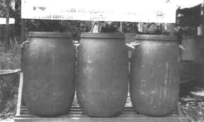
Irrespective of the size of the harbour, the best receptacle to store wet wastes in until they may be recycled or disposed of, is airtight PVC drums like the one shown in Figure 58.
Figure 58: PVC AIR-TIGHT BARREL
These airtight containers should be placed at vantage points all round the harbour, including fish handling areas and points of sale. They should not be placed in comers and hidden away from sight. They should be placed in cool sheltered spots away from direct sunlight.
Fishmeal is a valuable source of protein for livestock. It also contains useful quantities of nutrients, vitamins and minerals. It is generally believed that many commercial fishmeal plants have failed because of inadequate raw material supplies. Even at the cottage industry level, a careful assessment should be made of the economic viability of establishing the plant.
Although all kinds of fish and fish offal can be used to make fishmeal, efficient utilization requires certain elementary precautions:
· The material should be reasonably fresh as spoilt fish may reduce the nutritional value of the fish meal;· Certain tropical fish (like puffer fish) contain toxins and should be excluded;
· The offal must not be collected off the ground (free of sand and mud) but from airtight plastic barrels placed purposely around the harbour area.
A simple method to obtain fishmeal on a cottage industry level to process around 300 kg/day is described below.
The processing method
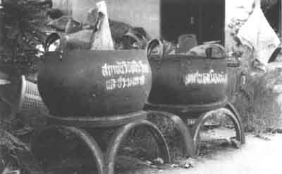
i. Cooking: The raw materials, after washing, are cooked in a boiling drum (Figures 59 and 60) for 15 to 20 minutes;ii. Pressing: The well-cooked mass is put into a press drum and maximum pressure applied for about 15 minutes to drain all the liquid away;
iii. Crushing: The pressed cake is put into a grinder and crushed; crushed fragments drop through a sieve at the bottom of the drum;
iv. Drying: The crushed meal is spread over a mat for sun-drying. During drying, the crushed mass is raked over from time to time. After one full day, the partly dry meal is spread over the drying pan and heated by two heaters. (Figure 61).
v. Grinding: The dried material is ground using the grinder for 10 to 15 minutes.
vi. Sifting: The ground meal is sifted using a sieve of 3 mm mesh. The retained material should be further dried.
vii. Bagging: Cooled ground material is packed in jute bags and stored in a dry and cool place. Careful and quick handling at this stage is important to minimize insect infestation problems.
viii. Utilization of stick water: Protein can be recovered from the stick water during the boiling and pressing stages. At the end of boiling, skim off the oil layer and mix this with the meal in the drying pan in the ratio of 2:3 and continue the drying process. Stick water collected from the press is dealt with in the same way.
Figure 59: SEQUENCE OF FISH MEAL PROCESSING
Figure 60: COMPONENTS OF A MINI FISH MEAL PLANT
HEATER AND BOILER
SCREW PRESS
Figure 61: COMPONENTS OF A MINI FISH MEAL PLANT
DRYING PAN
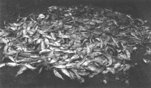
Figure 62: TYPICAL BY-CATCH USED FOR FISHMEAL PRODUCTION
As an alternative use of fish waste and offal, fish silage for animal feed is another possibility. One of the main advantages of fish silage over fish meal is low energy and capital cost. Energy is required only to grind the fish and mix it in formic acid (2 - 3 %) to reduce the pH level or a fermentable carbohydrate source and a culture of lactic acid producing bacteria. Another advantage over fishmeal is that its manufacture is not accompanied by an unpleasant odour.
The addition of formic acid encourages the breakdown offish tissue by its own enzymes, while at the same time inhibiting the activity of spoilage bacteria. After one to three days, a stable free running liquid is obtained whose protein content is similar to that of the raw material. This liquid may be directly incorporated in feeding regimes for pigs, or it may be dried with a carbohydrate carrier like rice bran for feeding poultry.
Manufacture of silage is done by comminuting the raw material, mixing in the acid and allowing the product to liquify. On the small scale (batches of say 50 kg) these operations can be carried out manually.
![]()
![]()
![]()